|
|
|
|
|
|
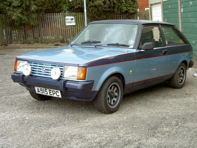
great cars ,had mine for 29 years
|
| |
|
|
|
|
|
|
|
|
|
|
Absolutely love this build, its gonna be mint when it’s finished, keep up the good work.
|
| |
|
|
|
|
|
|
|
|
Not sure how I've missed this one - awesome build!
|
| |
|
|
|
|
|
|
|
Ah ha. Having finished badly painting the suspension parts i decided to have ago at the back axle. The back axle is a sort of smaller Salisbury type and has been referred to as a 3HA but i don't think it is. Traditionally people considered them weak due to the diffs failing this mainly because in the old days people didn't use LSDs so the centre pin or the spider gears failed. Driveshafts are quite strong but will fail in the rough. Skip Browns always said that the axle will take 190hp if used in a rally car. The next failure point is the pinion but this only gets unreliable below 4.7 ratios it seems. So with potentially north of 260 from the V6 what did i choose? Luckily i have a dana 30 and two Volvo 1031/1041 axles in narrow and wide. So i snored these and built up a standard axle. First thing was to find the later more beefy drive shaft Not this one 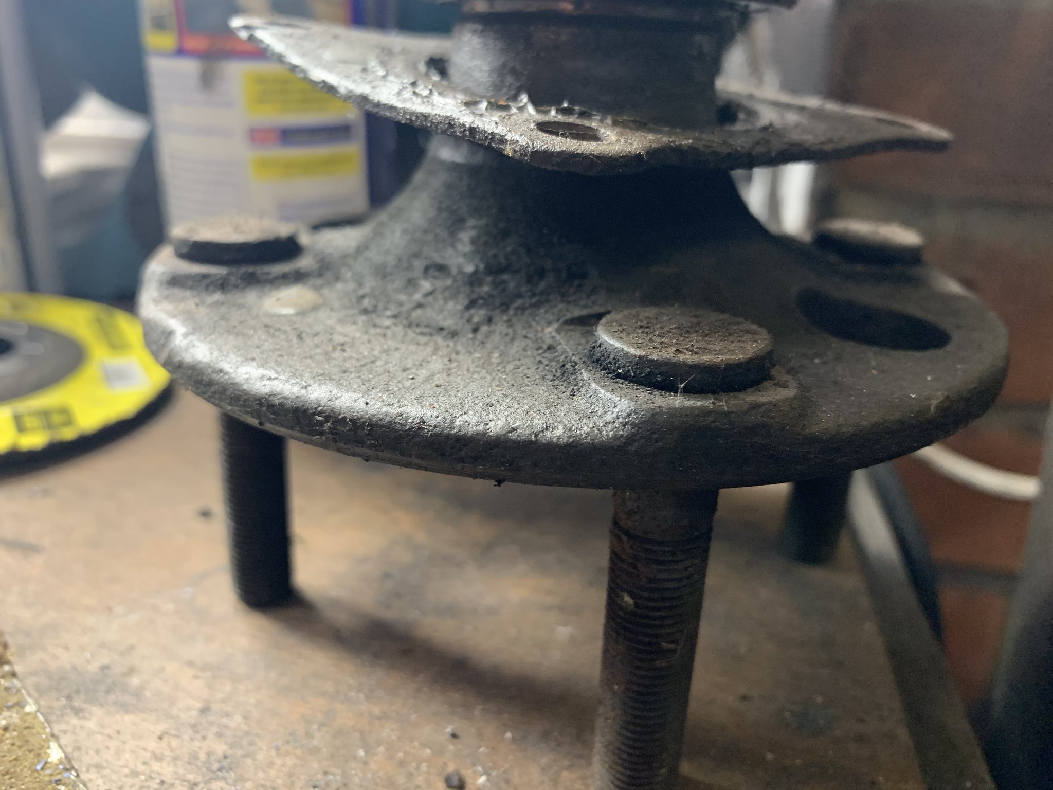 Untitled Untitled by Nevtiger, on Flickr This one!  Untitled Untitled by Nevtiger, on Flickr As can be seen the flange is thicker. I had a standard axle with normal tubes so used that rather than the thick tubed Lotus axle. It also had a 3.9 CWP which i think is the sweet spot.  Untitled Untitled by Nevtiger, on Flickr Taking off the CROWN Wheel to put on this.  Untitled Untitled by Nevtiger, on Flickr This the Quaiffe torque bias diff. I have used it before and apart from being quiet i don't really rate them but it was in a drawer doing nothing so..... Untitled by Nevtiger, on Flickr Fitted the 3.9 CWP and then set the back lash and check the engagement with Engineers Blue  Untitled Untitled by Nevtiger, on Flickr Seemed all ok. The proof will be if the axle holds together of course! But i will be using 185/60 x 13 so they should break traction first....... |
| |
|
|
|
|
|
|
|
|
nice, you don't rate the quaife? interested in why
|
| |
|
|
|
|
|
|
|
|
The quaiffe is not a slip limiting device. If one wheel gets away from it then it will just spin away.
Therefore it is difficult to do a proper donut.
I like doing donuts.
Therefore i don't rate it.
But it was hanging around so it got used.
|
| |
|
|
|
|
|
|
|
So the diff is in and the drive shafts put in as well. I put heavy duty retaining plates on to help them stay as well after i pressed on new bearings. A little earlier i had removed the old bushes using both methods  Untitled Untitled by Nevtiger, on Flickr  Untitled Untitled by Nevtiger, on Flickr Then fitted a set of poly bushes. Then it was time to fit the brakes, brace and back cover. The back plates are manual adjust ones which are quite rare on the Avenger/Sunbeam axle and i didn't have the actuating arms so i bought some MGB ones and modified them  Untitled Untitled by Nevtiger, on Flickr And they more or less fit!  Untitled Untitled by Nevtiger, on Flickr I fitted the brace and the rear cover after painting the rear cover. That is full Gold metallic and Lacquer. No idea how long it will last but i like it.  Untitled Untitled by Nevtiger, on Flickr |
| |
|
|
|
|
|
Jun 18, 2020 15:43:27 GMT
|
SO i had done building the axle and had it ready to fit the shell. Trouble was the shell was on the Spit, which meant breaking out various methods of lifting. My favourite being the block and tackle my dad let me have years ago:  Untitled Untitled by Nevtiger, on Flickr Then at the back i used the trusty engine crane ( i say trusty but has tried to kill me recently) Not quite ready for the lift as the chains aren't on yet but i forgot to take more photos:  Untitled Untitled by Nevtiger, on Flickr Front off Untitled by Nevtiger, on Flickr Back off and on stands  Untitled Untitled by Nevtiger, on Flickr Might as well fit the back axle and get it out of the way, the bowls are either protecting my head as i hadn't removed the hanging irons or a trial for super light weight bumpers - i can't remember.  Untitled Untitled by Nevtiger, on Flickr And in  Untitled Untitled by Nevtiger, on Flickr But what a pain in the ass it was. I bought a few years ago a complete set of Stainless bolts for the suspension off of a friend who was doing sets for the Sunbeam. What i didn't realise was the nuts were some sort of mad one use only affair and because they rn tight caused about 50% of the bolts to spall and seize. Didn't even know the Stainless fixings have this issue and hadn't come across it before. This led to some furious Googling and now i know its a thing. So i have purchased a whole bunch of Nylon nuts and use di -something sulphate grease to alleviate the issue. Copper ease in is insufficient apparently to completely cure it. Anyway my new battery - or cordless - grinder got me out of trouble. Again. |
| |
|
|
jonomisfit
Club Retro Rides Member
Posts: 1,788
Club RR Member Number: 49
Member is Online
|
|
Jun 18, 2020 17:29:19 GMT
|
|
Stainless is great in the right application.
But it's galls like crazy if your not careful. For me you only use them in mated threaded form if one has a surface coating applied (like a PTFE based coating) or there is a 50 Rockwell C difference in hardness between male and female parts. Moly works ok, but it really needs to be a bound coating not topical
The sliding contact in the threads exacerbates the situation as pressure and sliding contact tends to be what initiates the galling.
A lot of the stainless bolts are 304 (or similar) so really aren't that strong especially compared with normal 8.8 and 12.9 bolts.
The last bit is it can also accelerate corrosion in plain steel it's touching, especially where there is salt laden moisture trapped. Washers are great for this if it's stainless bolt onto mild steel washer.
I do like seeing an update for this pop up in my bookmarks.
|
| |
Last Edit: Jun 18, 2020 17:45:25 GMT by jonomisfit
|
|
|
|
|
Jun 19, 2020 10:01:54 GMT
|
|
Now that is some very interesting information! Cheers
I only went for Stainless as i thought it might increase the longevity of the car!
Any way the next car, which will be another Hillclimb is going to have a rifle drilled bolts...... I have even managed to get a lathe and mill to fulfil my dream od complete self sufficiency. Apart from not knowing what i am doing of course.
But learning about the Stainless bolts issue has been interesting.
|
| |
|
|
|
|
jonomisfit
Club Retro Rides Member
Posts: 1,788
Club RR Member Number: 49
Member is Online
|
|
Jun 19, 2020 10:32:54 GMT
|
In some ways I find the metallurgy aspects of being an engineer some of the most interesting. It has certainly led to some of the bigger challenges I've been faced with. And leads to the situation that I love some grades of stainless and despise others. Https://images.app.goo.gl/RvKwDEQ89QTCabnP7The bigger the difference, the greater the potential for corrosion effects on the lower item NAS bolts and K nuts are always good. |
| |
Last Edit: Jun 19, 2020 10:37:48 GMT by jonomisfit
|
|
|
|
|
Jun 19, 2020 19:42:14 GMT
|
|
I used to work for a company designing and restoring high end shop fronts and doors. The first time I saw the effects of galvanic corrosion it put me off from using stainless bolts on a vehicle, even in non-structural applications. We had in a restoration of aluminium frame (without a barrier coating) and stainless clad doors, this along with added salts over time from people urinating on it in the shop doorways made the ali blow and delaminate like wet MDF does
|
| |
|
|
|
|
|
Jun 19, 2020 19:53:39 GMT
|
|
Loving the thread btw, just read it through. I remember my friends mum driving us in one, albeit a Talbot in red, and remembered it having the sun damaged dashboard when I saw yours.
|
| |
|
|
|
|
|
Jun 19, 2020 20:44:53 GMT
|
|
Your doing a fantastic job on that wee car hats off to ye
|
| |
|
|
|
|
|
Jul 13, 2020 11:04:55 GMT
|
With the car on the ground and the axle in, it was time to fit the engine and gearbox to the shell. Which is quite exciting! Having attached the two units i realised that the best way to fit would be to lift the shell and lower over the engine assembly. That meant building a skate for the engine and gearbox:  Untitled Untitled by Nevtiger, on Flickr The wheels are all good but i didn't support them properly so have bent after use. Easily rectified with an extra brace or two for the wheels to site on. But before that i fitted the fuel tank.  Untitled Untitled by Nevtiger, on Flickr I'm not sure i got the right exit points here! Ho hum. I think it will be ok.... Engine almost in but shell back down  Untitled Untitled by Nevtiger, on Flickr Then some lifting and fitting of mounts etc and the steering rack to see if there is the clearance i had thought! Yes there is:  Untitled Untitled by Nevtiger, on Flickr  Untitled Untitled by Nevtiger, on Flickr  Untitled Untitled by Nevtiger, on Flickr Excellent. Lets try some exhaust manifolds Near Side  Untitled Untitled by Nevtiger, on Flickr This is going way to easy - and it doesn't fit the Off Side. To be fair i didn't think it would due to the starter motor being the standard position and the MX5 has it somewhere else! Lets see what else doesn't fit! These:  Untitled Untitled by Nevtiger, on Flickr  Untitled Untitled by Nevtiger, on Flickr So i got some different bends and cut the originals off.  Untitled Untitled by Nevtiger, on Flickr  Untitled Untitled by Nevtiger, on Flickr  Untitled Untitled by Nevtiger, on Flickr Thats better but still not fitting both sides. So lets see if i were to raise the inlets up 15mm  Untitled Untitled by Nevtiger, on Flickr Still plenty of room. BUT i need to move the mounting flange for the TB forward and rotate slightly due to the presence of the inner wing. I have now run out of talent as my MIG doesn't seem to have Carbon Fibre feed available. I know what needs to be done. But now how to do it. I need to make the carbon tube bit longer!! |
| |
|
|
|
|
|
|
|
Time for a bit of fabrication. In the old days when i was first getting into Avengers and Sunbeams one of the best things to do was drill the TCA mounting hole 10-12mm further out. This gave the car some decent negative camber which helped all round. What it didn't do was improve the already bad bump steer. But the gains from increased camber and a slight increase in castor worked well. The best solution is to keep the hole where it should be. Move the rack back by an 'amount' and lengthen the TCA its self. Thus, i found some old TCA's and cut the end off.  Untitled Untitled by Nevtiger, on Flickr Then after cleaning them up i welded a bolt onto it like so:  Untitled Untitled by Nevtiger, on Flickr Please note that small decorative paving slabs make excellent cooling pads. But just a bolt wouldn't be strong enough on its own so  Untitled Untitled by Nevtiger, on Flickr  Untitled Untitled by Nevtiger, on Flickr Which gives us this  Untitled Untitled by Nevtiger, on Flickr Time for some paint. Progress is slow on the Sunbeam at present due to the Tiger and next door. I have sold the engine from the Tiger and i am building a Big Ass shed next door to put all the stuff from the garage that shouldn't live in a garage, like bikes, bbq, lawn mower etc.... Then i can instal the lather, Mill, Saw, Drill etc. |
| |
|
|
|
|
|
|
|
So where was i with this? Ah yes the Tiger got in the way for a while So!!! Back in the place to start work again...  Untitled Untitled by Nevtiger, on Flickr |
| |
|
|
|
|
|
|
|
With the car back in the open i can get on with where i left off :-) I last was thinking about raising the inlet plenums up by 15mm. Therefore with a block of 15mm alloy i started making some raisers.  Untitled Untitled by Nevtiger, on Flickr With the inlet ports made and the raiser all shaped up i needed to ensure that the inlet plenum, the raiser and the inlet ports all align! I clamped up the two pieces and drilled 2 4.2mm holes.  Untitled Untitled by Nevtiger, on Flickr Then i tapped the holes M5  Untitled Untitled by Nevtiger, on Flickr And then bolted the inlet plenum to the raisers and achieved repeatable alignment. I suspect these two will stay attached to each other.  Untitled Untitled by Nevtiger, on Flickr  Untitled Untitled by Nevtiger, on Flickr That leaves the gasket to make and the alignment with the original lower inlet manifold. There is an original sealing gasket that incorporates alignment dowels so i shall replicate these. But before i do that i need some nylon dowel delivered. in the mean time i made up the inlet plenum support pieces. In the MX5 kit these are obviously the correct height. I need to raise them by 15mm. I used some offset Carbon Fibre sheet i had. These have been bolted and Voodoo glued......  Untitled Untitled by Nevtiger, on Flickr Then i needed to add the elbow. I found that the throttle body would sit in the correct orientation but not the cable mounts so i mounted them 90 degrees round. These are mocked up with black racer tape.  Untitled Untitled by Nevtiger, on Flickr  Untitled Untitled by Nevtiger, on Flickr All i needed to do then was mark the angle and Voodoo glue the elbows on properly. I then moved to the Near Side. curse word 15mm isn't enough. I mocked up 30mm and found that will allow the elbow to fit with minor modification and still fits under the bonnet. Just. Its because the Near Side bank of 3 are offset rear ward.  Untitled Untitled by Nevtiger, on Flickr So need Alloy block, nylon rod and some Flexed gasket material and i can finish off the inlet arrangement. |
| |
|
|
|
|
|
|
|
|
Just caught up on the whole thread. Awesome work man. I've always been fond of Sunbeams. One of my favourite 'little moment' memories is when I was in my XJ40 and pulled up to a chap in a Sunbeam Lotus at the lights. I got the better launch but then he came tearing past me at full chat. Big grins all round.
Love the burnt yellow as well. I hope that's staying!
|
| |
|
|
|
|
|
|
|
Just caught up on the whole thread. Awesome work man. I've always been fond of Sunbeams. One of my favourite 'little moment' memories is when I was in my XJ40 and pulled up to a chap in a Sunbeam Lotus at the lights. I got the better launch but then he came tearing past me at full chat. Big grins all round. Love the burnt yellow as well. I hope that's staying! That Burnt Yellow is called Sweet Corn and yes its very much staying. As it happens my mate has just bought a Sunbeam in exactly the same colour and almost the same interior trim. So there will be two of them round these parts. |
| |
|
|
|
|