|
|
|
|
|
I have both inlet raiser pegged to the inlet plenums. The nylon rod has turned up to allow me to fix the position of the raiser to the injector manifold as well. I needed to seal and permanently join the two risers for the near side. The upper and lower have been dowel using 2 M5 cap heads.  Untitled Untitled by Nevtiger, on Flickr But in the mean time i though i might start painting them so they aren't quite so noticeable. First some primer filler  Untitled Untitled by Nevtiger, on Flickr |
| |
|
|
|
|
|
|
|
|
|
Whilst i was waiting for the paint to dry and the rain to stop i had a crawl about in the 'Bits and Bobs' store. I thought i had placed all the Sunbeam bits that i had removed from the shell in various boxes up there as i was getting to the point of needing to plumb the cooling circuit, plumb the brakes, fit the alternator. I found all the stuff but my 3 row Sunbeam lotus radiator has taken a knock :-( but it will be ok for fitting up etc. Therefore i started with the brakes. I wanted to keep the standard arrangement with servo. That meant getting the pedal box and servo into place. I soon hit a snag. This isn't even pretending to be close to fitting.  Untitled Untitled by Nevtiger, on Flickr Ok, the Tiger cam with a remote servo set up. Cool. look that out from the spares but soon realised its a single circuit system. I don't overly like that. Hmmmm. I then had a tinker with this lot: 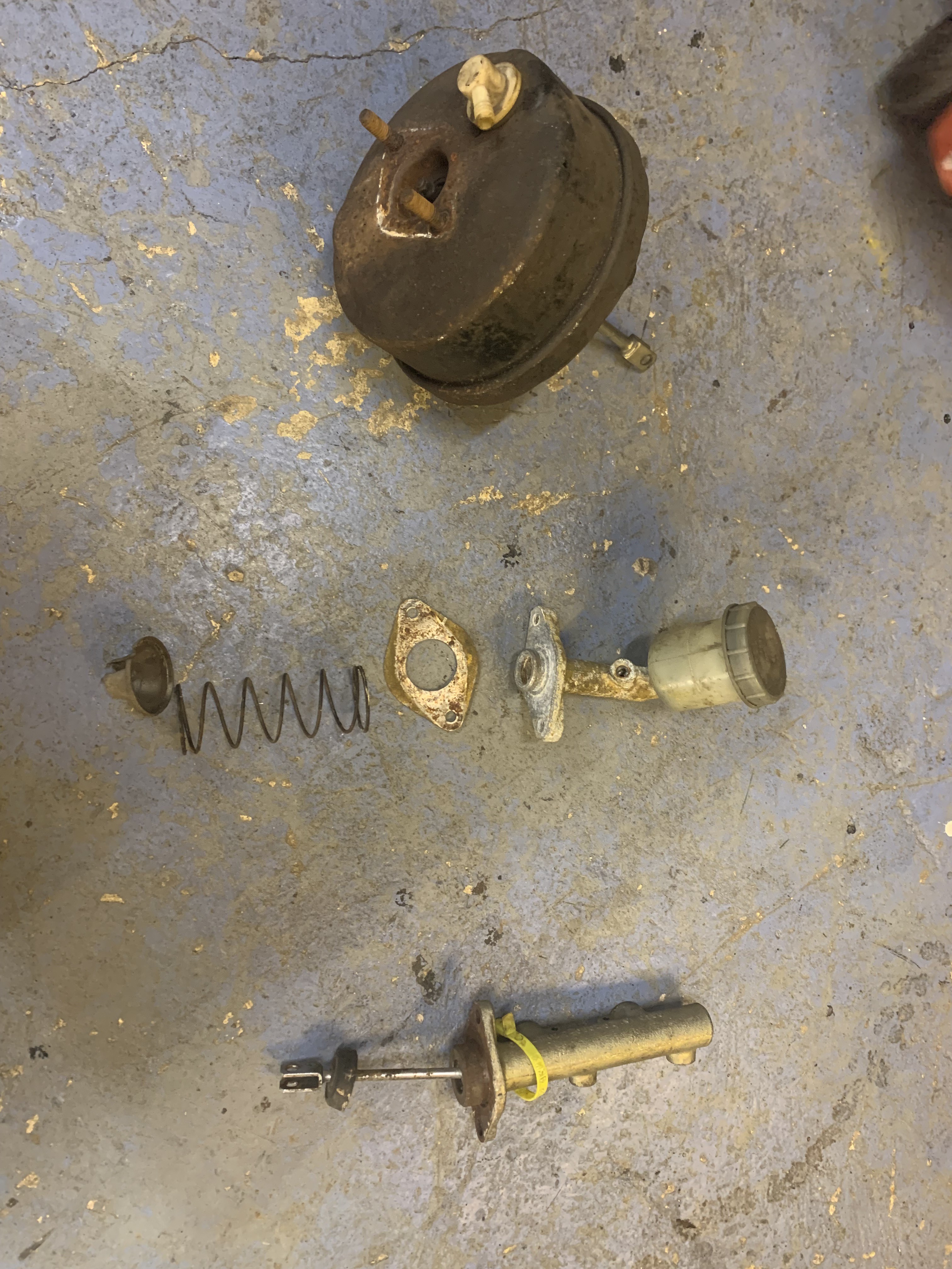 Untitled Untitled by Nevtiger, on Flickr Centre is the original Tiger Master Cylinder that feeds the remote servo but bolts to the bulkhead and the brake pedal. The other bits either side are the Sunbeam servo and its master cylinder. I wonder of i can make the Sunbeam master cylinder do the same as an original Avenger one? Yes  Untitled Untitled by Nevtiger, on Flickr Many more rooms  Untitled Untitled by Nevtiger, on Flickr The later Sunbeam pedal box even retains the mounting holes for the single master cylinder  Untitled Untitled by Nevtiger, on Flickr Bulkhead doesn't of course  Untitled Untitled by Nevtiger, on Flickr I will need to make a collar to locate the master cylinder into the hole centrally - probably - but otherwise i t will fit. I know non servo brakes aren't the ideal for a road car but i am used to it on the Tiger so i think it will be ok. I shall retain the standard master cylinder bore (Sunbeam Lotus) or as close as i can get to allow a reasonable pedal as the front brakes are a similar piston section area. The other option is to just servo the front brakes but i like that less as an engineering solution due to getting the balance correct. |
| |
|
|
|
|
|
|
|
|
If you're going non-servo anyway it shouldn't be too tricky to get something sorted for a bias bar setup. Two single master cylinders attached to the bulkhead and the sleeve of the bias bar let into the pedal.
Of course, that's not a great deal different than just having an unservo'd tandem master, but would be shorter so might offer a bit more usable space.
I'd advise moving the pivot pin up on the pedal so you get more leverage for the manual brakes. I'm not sure what the standard pedal ratio is, but if it's designed for servo brakes you can get a bit less of a wooden pedal by upping the ratio.
|
| |
|
|
|
|
|
|
|
|
i have a spare bias box as it happens, but wanted to stay with a 'simpler' set up. I might just have a look later....
As it happens the pedal box pivot points have been the same through out the Avenger and Sunbeam life span so the Avenger non servo brake pedal pivots at the same point as the later servo'd cars.
|
| |
|
|
|
|
|
|
|
|
when I deleted the servo from my Elan I went to the next size down master cylinder, pedal travel didn't noticeably change and the pedal feel was much better, with the original and no servo it was a bit wooden with no initial bite.
|
| |
|
|
|
|
|
|
|
|
The standard Master Cylinder is 19mm, Avenger estate is 20.5mm (still the same brakes though). When fitting bigger front brakes, 4 pots etc its generally the 'thing' to fit either a SAAB 900 master cylinder at 22.5mm or Land Rover at 25mm.
So logic indicates - as I'm to lazy to do the maths - that as i have larger 4 pot callipers fitted i would normally fit a 25mm land rover master cylinder when using a servo. But as i am not using the servo i think the 19mm standard size will be close to ideal. If it has too much travel i can go up a size to the estate master cylinder. The thing i cant do is go down in size though!
|
| |
|
|
|
|
|
Nov 22, 2022 15:27:02 GMT
|
Ok, seems that's going to work but i need to do some strengthening and sealing against weather, fire, fluids etc. I have tried to keep any modifications to the shell to a minimum (transmission tunnel being the only transgressor) so i made a plate. In aluminium and some gaskets.  Untitled Untitled by Nevtiger, on Flickr The big hole was done with a step hole drill cone drill bit thing. I had one big enough.  Untitled Untitled by Nevtiger, on Flickr More gasket.  Untitled Untitled by Nevtiger, on Flickr That is done and can bolt up but i need to do the throttle cable and the clutch. With the pedal and the TB in their 'rest' positions i have some slack.  Untitled Untitled by Nevtiger, on Flickr Now i don't have slack.  Untitled Untitled by Nevtiger, on Flickr Clutch next. This is the Master Cylinder  Untitled Untitled by Nevtiger, on Flickr And the only real place it can go which is out of the way and mountable is here:  Untitled Untitled by Nevtiger, on Flickr The clutch pedal will give a straight push to the cylinder. It does need modifying though slightly. 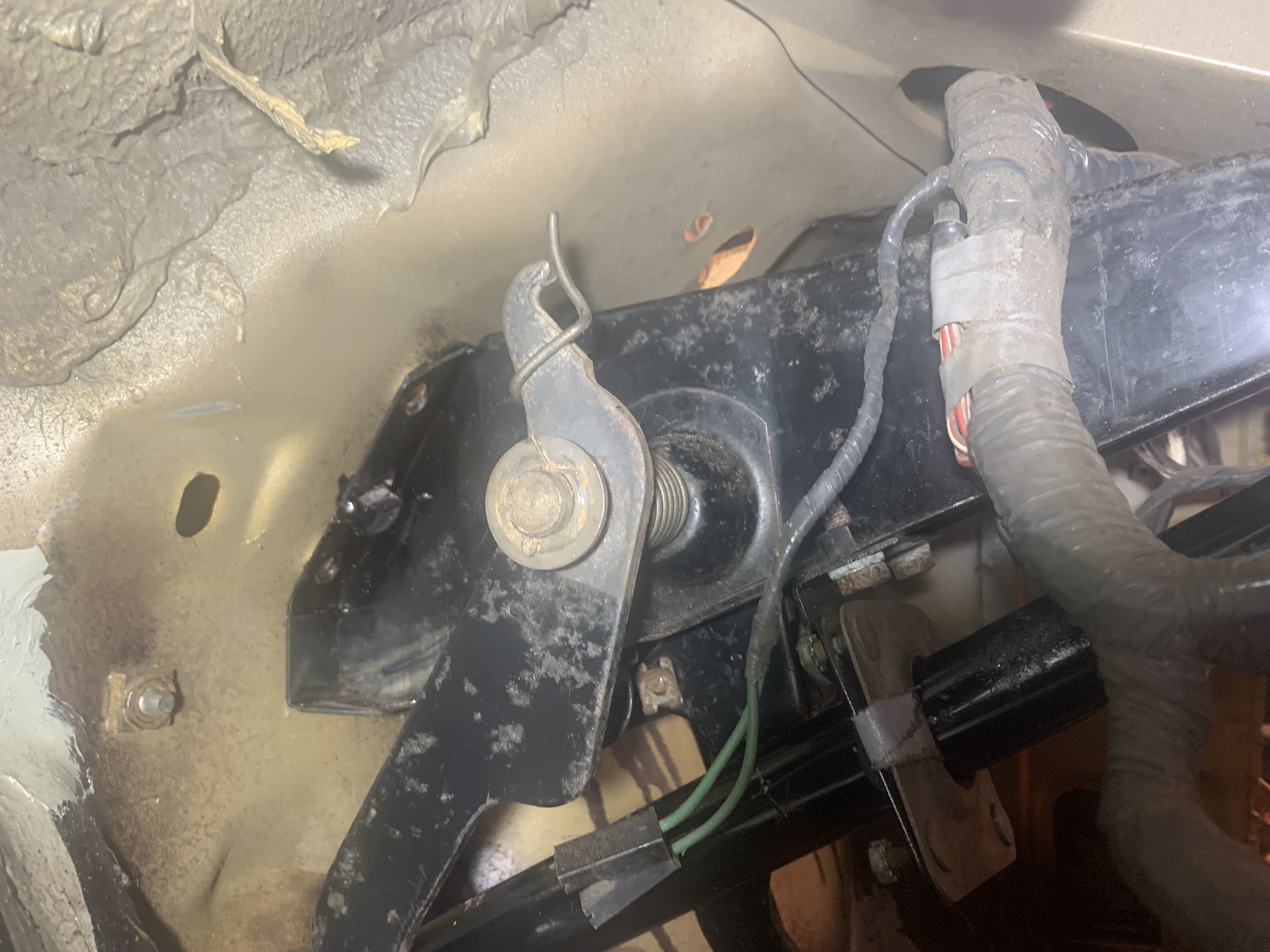 Untitled Untitled by Nevtiger, on Flickr This will bolt - somehow - unto the column mount and then the MC goes more or less on it like this. Final mounting and welding will happen once i have the actuation rod made and i can get proper alignment sorted.  Untitled Untitled by Nevtiger, on Flickr Note i have started to have to write which way stuff goes around now! I got into a right mess with the inlet spacers..... MC has a piston with a dished face - deep down - that will allow some misalignment. 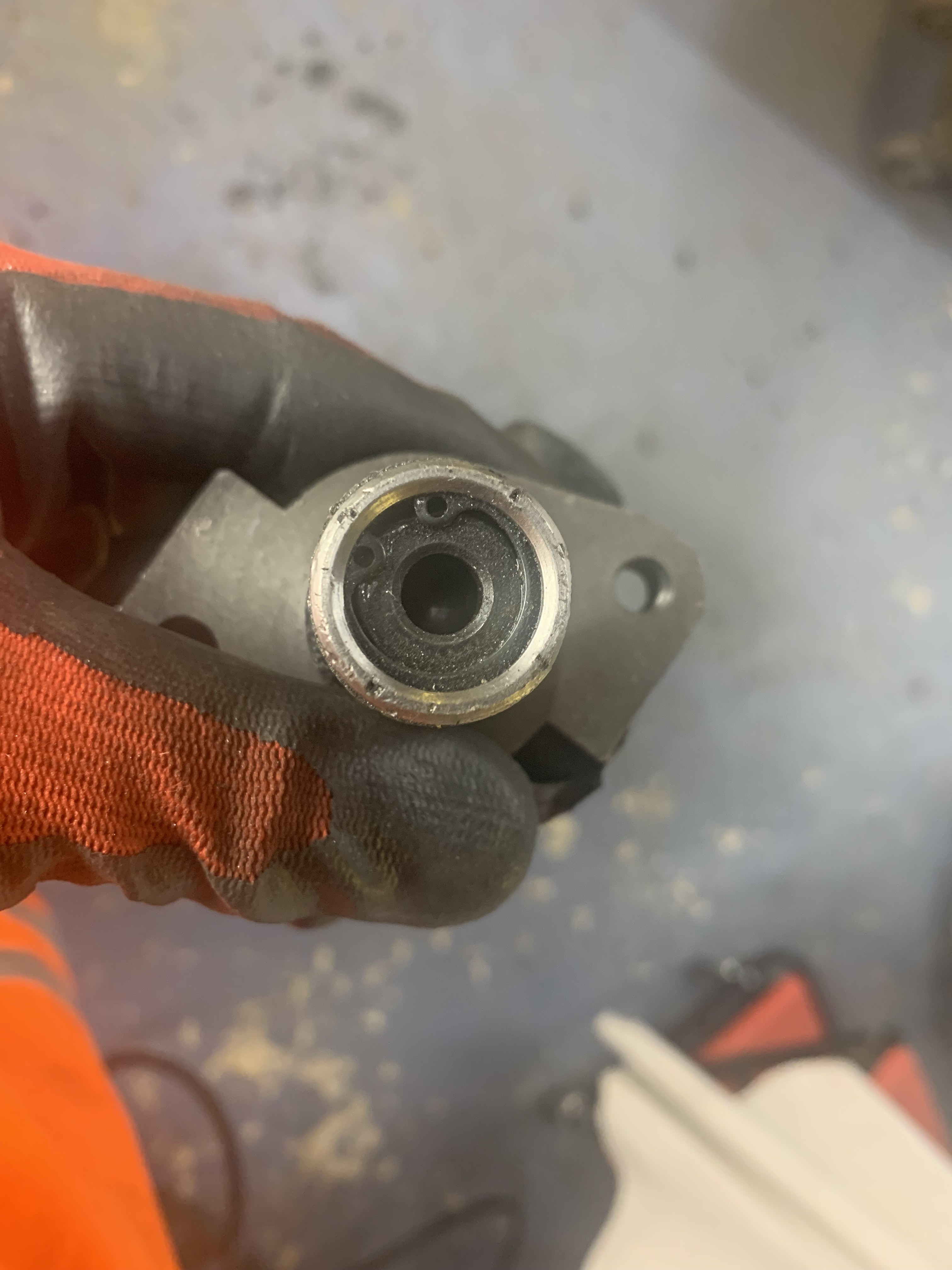 Untitled Untitled by Nevtiger, on Flickr Just have to make the actuating rod now. I have some steel bar and a lathe..... However, whilst i am trying to do that all first i did have a look at the near side and whether the inlet elbow will fit. Its an interference fit by approx 2mm.  Untitled Untitled by Nevtiger, on Flickr That's easy, i shall just create some clearance on the elbow and reverse curve some carbon fibre in the hole. It shouldn't affect airflow enough to be noticeable. And there is another Sunbeam within my group of mates round these parts: so i looked out some front springs to help him on the way. I didnt realise i had some many rear and front sets at different rates.  Untitled Untitled by Nevtiger, on Flickr |
| |
|
|
|
|
|
Nov 22, 2022 15:40:56 GMT
|
Neat  what front and rear brakes are you using? Can do some balance calcs and see what you're coming out at, as well as compare the pedal weight to some known setups and see what it'll be like. |
| |
|
|
|
|
|
|
|
biturbo228 I am using standard Sunbeam at the rear and the front is a larger 4 pot and disc. I don't know the piston diameters off the top of my head so would need to look them up or at least measure them.
|
| |
|
|
|
|
|
|
|
Meanwhile i mounted the mounting plate. Drilled some holes and fitted some flush M6 rivets  Untitled Untitled by Nevtiger, on Flickr Then bolted up the plate. 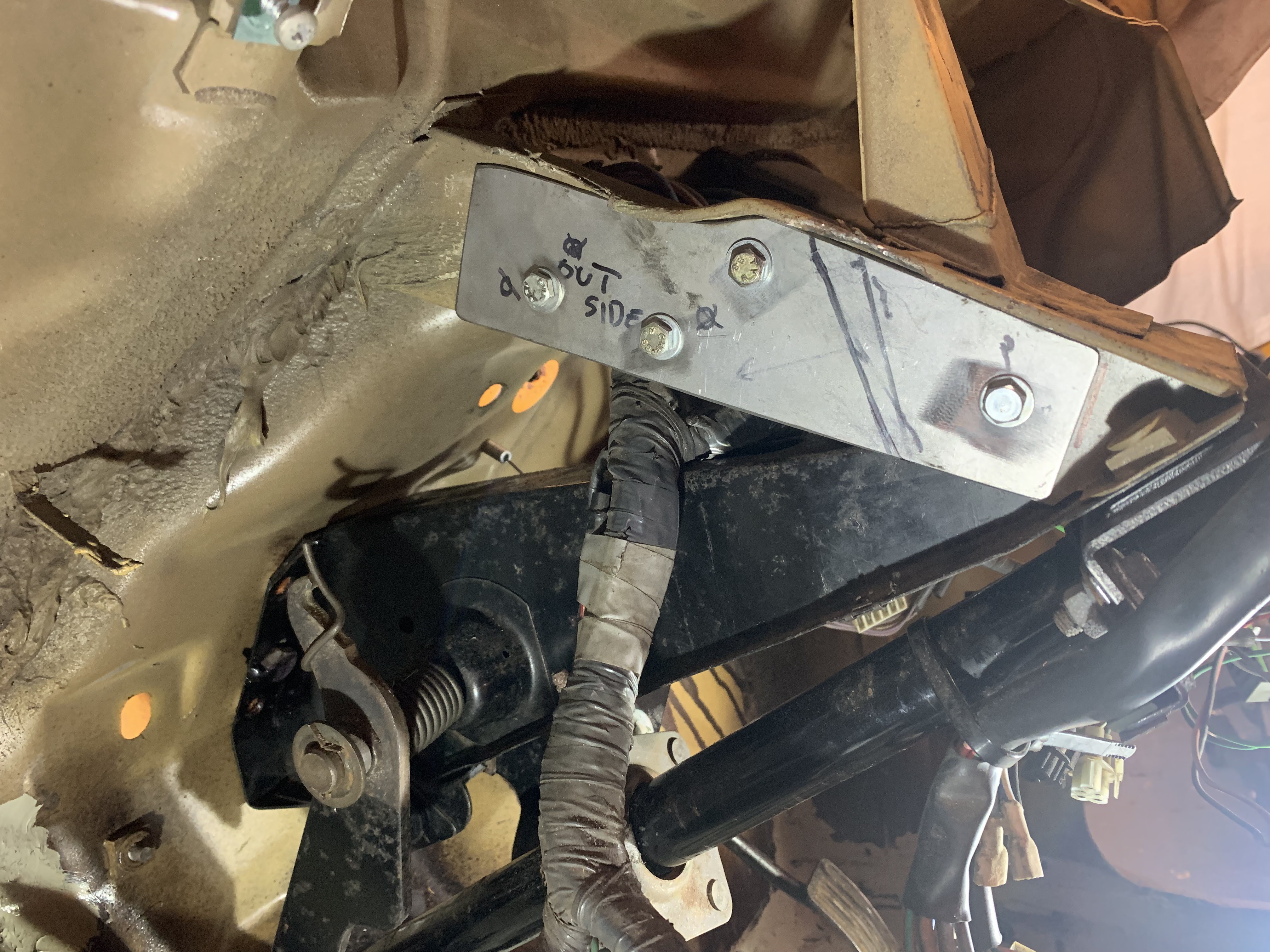 Untitled Untitled by Nevtiger, on Flickr Next challenge; the clutch pedal has a top designed to pull on a cable. I want it to push on a rod. A clevis and its pit sit in the recess where the cable sits. However, the pedal return spring stops it rotating fully and the pedal is a little narrow and doesn't give a square push. I didnt want to modify the pedal if i did have to but looks like i will need to do some cut - more cut - shape - weld - drill to get it working how it should. |
| |
|
|
|
|
|
|
|
|
|
Making a plate was the easy part. I then fired up the lathe and got some 12mm rsteel rod to make the actuating rod. This bit fits into the M/C. I'm not great with the lathe. I can get the right shape but the surface always seems a bit rough regardless of tool or speed. Anyway this was cleaned up with some grip paper.  Untitled Untitled by Nevtiger, on Flickr Seems to fit  Untitled Untitled by Nevtiger, on Flickr The other end needs threading for the clevis.  Untitled Untitled by Nevtiger, on Flickr That fits as well 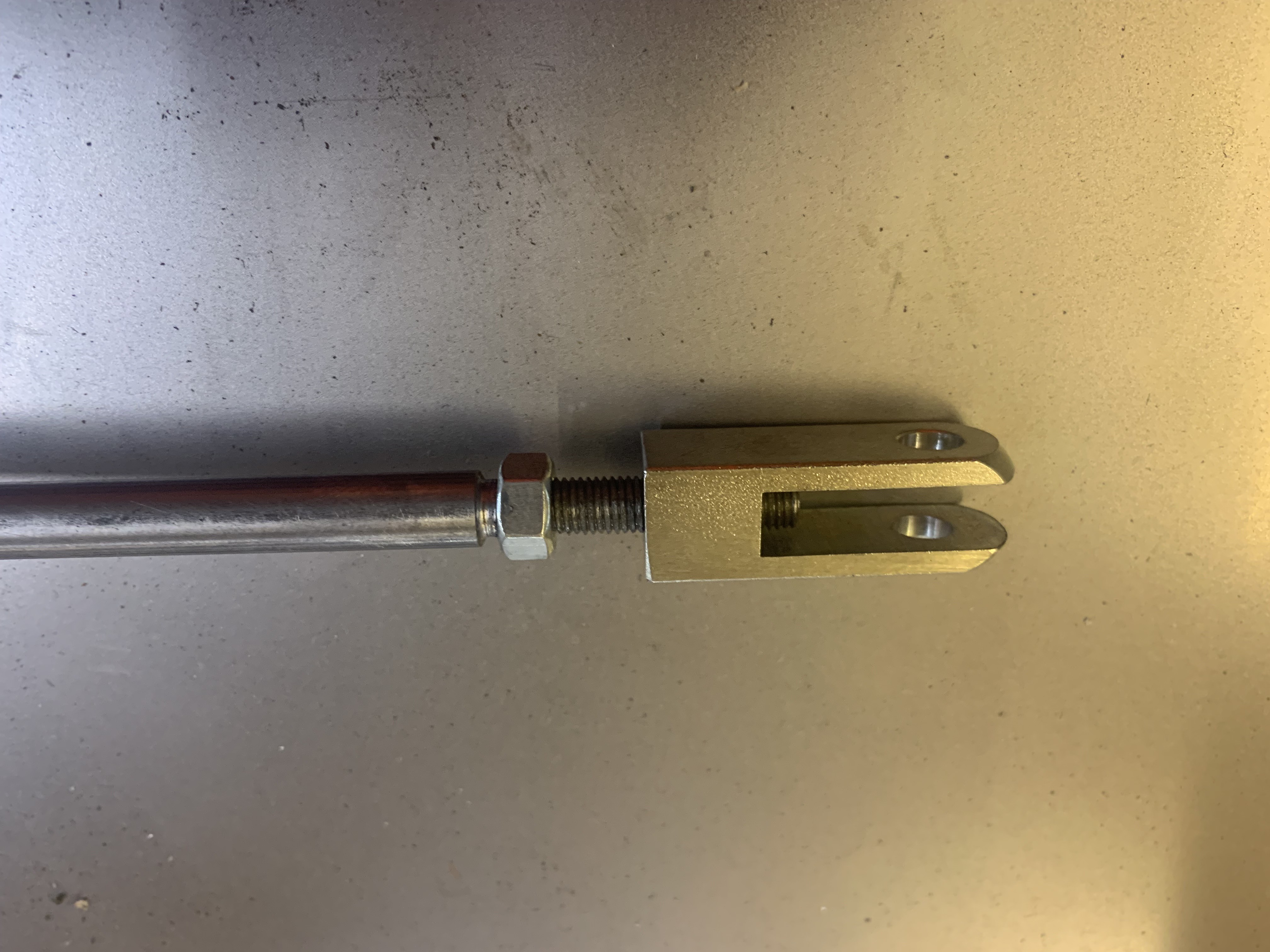 Untitled Untitled by Nevtiger, on Flickr And all together  Untitled Untitled by Nevtiger, on Flickr The pedal is designed for a cable to hook over and then be pulled but this arrangement means the part is trying to push so there is no positive engagement. I had some thinking and came up with a folded cover with the same hole as the pin in the correct position to allow the pin to bear on the pedal face. All the loading is into the pedal via the pin and the extra bit is for location upon pedal return. ( I say this because it seems people with proper Engineering Brains read these posts ) This was the second attempt. 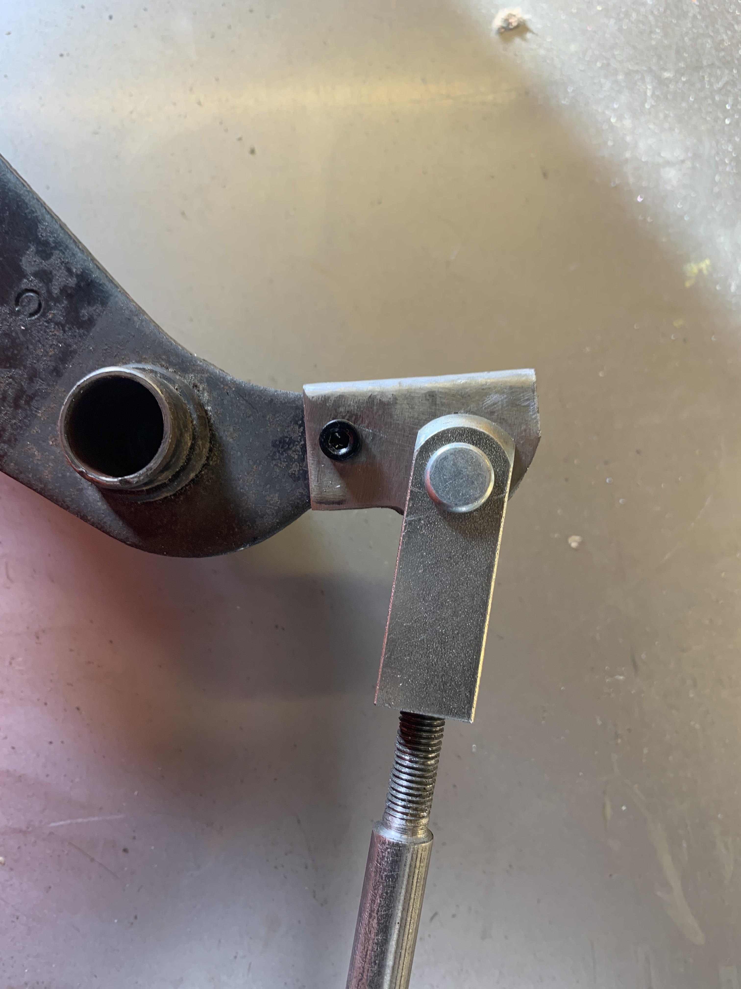 Untitled Untitled by Nevtiger, on Flickr  Untitled Untitled by Nevtiger, on Flickr Then it was time to align, mount, weld and fit. It took a few adjustments but the rod passes into the M?C with no rubbing and full travel is achieved. The black epoxy and the angle doesn't show the gussets but they are there and in the correct plane for force absorption,  Untitled Untitled by Nevtiger, on Flickr Then with pipe and reservoir fitting on.  Untitled Untitled by Nevtiger, on Flickr This should all be removable without having to take the dash out once everything is in. |
| |
|
|
|
|
|
|
|
The reservoir for the MC will sit up on the inner wing but needs a bracket. Here it is in the paint oven  Untitled Untitled by Nevtiger, on Flickr Since then i managed to pick it up with oily gloves and the paint wasn't hard so i have started again..... The back brakes on a Sunbeam have only one bleed nipple at one side as standard and it is really easy to bleed. Some how i have made the pipes with a T-piece in the middle and a bleed nipple either side. So i wanted to change that. Out with the T-piece  by Nevtiger, on Flickr Then search for enough braided hose and fittings to make a flexi pipe for the axle connection.  Untitled Untitled by Nevtiger, on Flickr  Untitled Untitled by Nevtiger, on Flickr I did and the fittings so made and fitted  Untitled Untitled by Nevtiger, on Flickr Quick wizz with the flaring tool and hey presto  Untitled Untitled by Nevtiger, on Flickr  Untitled Untitled by Nevtiger, on Flickr Just the handbrake cables to fit and the back axle was put back down. The other end at the hand brake its self proved a small problemm. First was finding the bracket arrangement from 'Deep Storage'. It took a while but found it. Gave it a clean and stuck it on. But the cables just won't reach. So i think i need to wind off the adjusters on the drums to give me a bit of play till every thing settles in.  by Nevtiger, on Flickr On a standard Sunbeam and Avenger from this era they had a Brake Pressure Warning Valve that if one circuit had a different pressure then a shuttle valve would move and make some contacts so a Brake Warning Lamp would come on the dash. But i am in two minds as to whether to refit it. All it does is light a light when the brake pedal is pushed and either the front or the rear circuit have failed. I suspect i will be interested in the lack of retardation than a lamp lighting up by my knee!!!     |
| |
Last Edit: Dec 5, 2022 18:59:05 GMT by nevtiger
|
|
|
|
|
|
|
|
If it's the same as the PDWA valves in Spitfires then they're notorious for leaking and causing problems. I vote simplify.
Also, what ferrules do you use for making your own braided lines? Are they screw-together ones like AN fittings or crimp ones?
|
| |
|
|
|
|
|
|
|
biturbo228 i use screw/bolt/remake fittings from Speedflow and Merlin. I only use PTFE lined on the Avenger so that is mostly what i have. I have got some rubber lined hose which i have used on oil lines. Means they are re-usable - with a new ferule - when ever i change something. It is different construction for sure, i just googled the Spitfire one. I shall take a shot of the Sunbeam one later. I am also a fan of simplicity as it happens and in my view less brake pipe line ends means less chance to leak. Although i have not heard of the actual PDWA causing issues on the Sunbeam.
|
| |
|
|
|
|
|
|
|
I decided not to use the PDWA device. So i got on and plumbed in the copper lines.  Untitled Untitled by Nevtiger, on Flickr Seems a pain really as its all got to come back out again for paint but its the only sensible way to do it in my Haynes 'How to V6 your Chrysler Sunbeam'. These tuck under the radiator nicely.  Untitled Untitled by Nevtiger, on Flickr  Untitled Untitled by Nevtiger, on Flickr Then i thought that i might as well put fluid in and bleed the brakes to see if there are any leaks from badly formed pipe ends etc. Rear brakes came up nice once i had tightened up some of the fittings..... The front callipers were weeping from the fitting into the caliper. Its a Taper fitting and i had put them in tight but evidently they needed more tight. These were supplied with the brakes, i don't think i would have done it like this through choice but i did the fitting through a full 360 degree turn and they don't weep at present but i haven't tried bleeding them yet as i ran out of time.  Untitled Untitled by Nevtiger, on Flickr  Untitled Untitled by Nevtiger, on Flickr Plenty of steady progress some of which doesn't need to come back off the car. Next job after bleeding the front will be to work out the fuel arrangement. I don't have the depth on the tank to do what i did with the Avenger (Range Rover pump) so i shall look at a swirl pot/pump/pressure regulator all in in one job unless some one has any stunning ideas? |
| |
|
|
|
|
|
|
|
|
Have you got any more pics of the swing arm mod? I’ve been thinking about doing something similar to my MGZR rally car…raising the ride height has created almost positive camber 🫣
|
| |
|
|
|
|
|
Dec 13, 2022 14:40:21 GMT
|
It won't let me write Dorset_Clive as a tag? Ah got to tag as something else!! Which swing arm mod are you referring to? |
| |
Last Edit: Dec 13, 2022 14:51:24 GMT by nevtiger
|
|
|
|
|
|
|
It won't let me write Dorset_Clive as a tag? Ah got to tag as something else!! Which swing arm mod are you referring to? This one…thanks  |
| |
|
|
|
|
|
Dec 15, 2022 10:07:23 GMT
|
Dorset_CliveAh, the TCA, Track Control Arm. So, i don't have more photos of it but if desperate you can either: Come and have a look your self (I'm on the Hants/Wilts border) or i take some more photos.... Essentially i took a standard long arm (We have two lengths for Avenger/Sunbeam) and chopped the bush using off. I then welded a threaded insert onto the main arm. Care here to ensure the insert is parallel to the arm from the vertical but is at the right angle in the horizontal which may be parallel for you. Add some strength with fillets etc. Then take a 12.9 bolt of the correct size/thread and weld that to the bush housing. Then add plenty of strength. Et Viola you have created your very own adjustable bottom arm. Depending on your application you could just make a complete new arm but I'm not familiar with the MGZR. So i googled it. As long as that is steel of some sort that will be easy to modify the existing.
|
| |
Last Edit: Dec 15, 2022 10:08:00 GMT by nevtiger
|
|
|
|
|
Dec 15, 2022 10:21:20 GMT
|
Ah, the TCA, Track Control Arm. Same, but wasn’t sure if that was just an MGR thing… Love to come and have a look, thanks. I’m up near Stonehenge so not far at all. |
| |
|
|
|
|
 Untitled by Nevtiger, on Flickr
 Untitled by Nevtiger, on Flickr
 Untitled by Nevtiger, on Flickr
 Untitled by Nevtiger, on Flickr


 what front and rear brakes are you using? Can do some balance calcs and see what you're coming out at, as well as compare the pedal weight to some known setups and see what it'll be like.


