RobinJI
Posted a lot
 "Driven by the irony that only being shackled to the road could ever I be free"
Posts: 2,995
|
|
Nov 26, 2019 13:57:20 GMT
|
|
I've had an R-Tech 180 amp MIG for 3 years now and always got on well with it, very nice and easy to use and it's not had even the slightest hick-up reliability wise. It seems to suit general car-guy stuff really well. I've run it maxed out for extended periods welding up stuff that was a bit thicker than it's really meant for (for work, when we've not wanted to lug our 3 phase machine to a site) and it put up with it happily. Our subcontract welder at work's got one too for site work and that's seen a crazy amount of abuse, including being dropped off ladders and run maxed out for most of its life. Again his hasn't given him any issues and it's a fair bit older than mine. The gas regulator that comes with it isn't the greatest, but other than squealing a bit occasionally mine's never actually given me any trouble and the torch and earth lead have lasted well. The torch feels a touch plasticky but seems hard wearing. I've used mine for a little stick welding too and although I don't have a clue what I'm doing with a stick, when in the hands of a friend who does it did the job well.
The Lotus is all looking awesome by the way!
|
| |
Last Edit: Nov 26, 2019 14:02:24 GMT by RobinJI
|
|
|
|
RobinJI
Posted a lot
"Driven by the irony that only being shackled to the road could ever I be free"
Posts: 2,995
|
|
Aug 14, 2019 12:51:50 GMT
|
Thanks guys. I'm kind of glad that everyone doesn't think I'm mental. It's just one of those things where circumstances have changed and the car isn't fulfilling the purpose I wanted it for. .... Might be worth getting it to rolling status 1st as it will probably open up the market a bit. Just don't get sucked down the rabbit hole with the E36! Get out on track with it and replace stuff as needed. Otherwise in 2 years time there'll be a similar thread for it! Tom A few friends have said that about getting it rolling when I've been mentioning the idea of getting rid of it. The issue is that I wouldn't be happy to sell it covered in custom built, safety critical parts if I've not been able to put a few closely monitored miles on them. I'd happily sell 'as is' leaving the decision of whether to finish and use the parts or not with the buyer, but selling 'finished' but untested parts isn't something I'd be ok with. As it stands, you could easily bolt standard running gear back into it with the exception of the interior and brake master cylinder, so hopefully there would be a market for someone to use it as a re-shell for a track car or something. I could buy some standard subframes (my ones are rusty & cut-up) and get it rolling that way, but frankly I'd rather knock the cost off the asking price and save myself the time and effort. Chances are I'll just sell it exactly as is unless the buyer had any specific requests. Even the rear-quarter panel that still needs sorting may not be worth doing until I know a buyer isn't going to stick 944 arches on it. If I was going to put time into making it more salable, I think getting it in paint may be the best bet. As for the rabithole with the e36, the plan is very much for it to remain as my rough around the edges daily driver, so I won't be able to go too mad. The new house is a short cycle ride from work, so I won't have to particularly worry about fuel economy, especially for shorter trips, which will allow me to have some fun engine-wise, but the car will have to stay practical, which combined with the fact I actually DO have some motivation for the Scirocco should keep things fairly sensible. Plus it's an e36, there's a quick, easy, bolt-on solution to most upgrades should I feel the need. The plan right now is an engine swap resulting in a reliable >300bhp, some bolt-on brakes, better coilovers & tyres then just run it and repair it. I'm sure I'll find other small bits to do like bushes and some nicer front seats, but they can be done as and when and it really shouldn't need much beyond that. Hopefully with that spec it'll make a nice daily driver that's capable of being fun on the odd track day & Sunday blast. I expect I'll need something to run around in while I do the engine swap, but that should hopefully take weeks, not months, so I'll literally buy whatever's local with a couple of months test and immediately get shot of it when the swap's done. Sonus mentioned storing the 924 until I'm in a better position to do it, but in reality I'm eager to free up the space it's taking up. Plus I'm pretty sick of having so many unfinished projects kicking around, my head's not been in a great place through most of 2019 and sadly I feel a de-clutter is something that's going to be needed to change that. (Along with actually getting back the social side of one of my main hobbies.) All of this does somewhat depend on how the house purchase goes but as you can probably tell from the way I'm writing about it, sadly I think the 924 might be going sooner or later  |
| |
Last Edit: Aug 14, 2019 14:19:36 GMT by RobinJI
|
|
RobinJI
Posted a lot
"Driven by the irony that only being shackled to the road could ever I be free"
Posts: 2,995
|
|
Aug 12, 2019 15:17:19 GMT
|
Thanks for the kind words guys. Sadly there are some bad thoughts running through my head at the moment with regards to the 924. I'm in the process of buying a house that's in need of some work and 10 minutes/8 miles further from the unit, which is going to be quite a big blow in terms of how much time and money I can commit to the Porsche. Even at the current rate of progress I'm pretty unhappy with how long this is all taking, especially considering I initially bought this to have something fun on the road while I re-built the Scirocco. That was the summer of 2015,  I've still not even started the Scirocco and I've spent all the time in-between trundling around in a gutless diesel daily driver. If I'd been able to keep up the momentum that I had when I started this, it would be done by now but sadly I've been finding it increasingly difficult to prioritise spending much time on it, both in terms of motivation and practicality. I've also been generally feeling a bit less free than I'd like in life, having so many projects on the go hangs over me slightly and the house (while necessary and worthwhile) sure as hell isn't going to help that feeling. Bearing in mind that the Scirocco has a lot more sentimental value than the Porsche, and the BMW both works/isn't a project, and is just too good at doing normal car duties to get rid of, it's feeling like the Porsche might be the one that has to go Realistically, unless I significantly change my priorities in life and spend a lot more time on it, the Porsche has another year to go at least and frankly I'm pretty sick of not being able to join in with friends on track days, car shows etc.. I've been a car guy with no car for a bit longer than my patience is OK with. My current thinking is that looking purely forwards, rather than getting hung up on where I've spent time so far, one solution would be along the lines of: - Sell the Porsche for whatever I can get for it as is. Hopefully someone would want a rust-free caged up shell as well as some of the 'early' parts I've got with it. - Use that money to fairly quickly throw a less terrible engine, some slightly better brakes and higher end coilovers in the e36, allowing me to use it for the odd track day and show. - Get started on the Scirocco, whilst my current plans are more drastic than the Porsche, I feel it's a project that's actually likely to progress faster due to the nature of the work that'll be involved. (For the most part it'll be less 'fiddly'.) This would hopefully not really cost me anything (depending on what I can get for the Porsche and the cost of doing the BMW), would give me a car that's on the road, fun, a bit interesting and still practical, and having the Scirocco would still let me scratch that itch to lock myself in a workshop and cut/weld/grind things. Plus, the Scirocco might actually see the road again whilst there's still some oil reserves left! As a bonus it would also free up some much needed space at the unit and whether I use it or not, it would at least give me the option to bring everything home once I've built a garage at the new place. Ideally I don't want to get rid of the unit (it's fun socially and keeps the neighbors happy) but I'd sleep better knowing that if I lost the space I had a back-up plan. Nothing's set in stone yet, but sadly I think this may well be the way things go as I'm struggling to find an alternative right now. So far my financial investment in the car is really quite low. I've put a lot of hours into it, but I've also enjoyed the time I've spent on it and learned a lot along the trip, so while I wouldn't exactly be happy not to see the fruits of my labors, I wouldn't be as disappointed as I maybe could be; none of it's been time wasted whether I finish the car or not. |
| |
|
|
RobinJI
Posted a lot
"Driven by the irony that only being shackled to the road could ever I be free"
Posts: 2,995
|
|
Jun 27, 2019 16:56:43 GMT
|
HI Robin, Any update's on the Porker ? Sadly I've not got a whole lot done on it, life's been managing to get in the way plenty and I've struggled to dedicate any time to the car. The BMW needing some attention hasn't helped either as the few chances I've had to do stuff have been spent keeping that going. What I have managed to do is weld these two up: 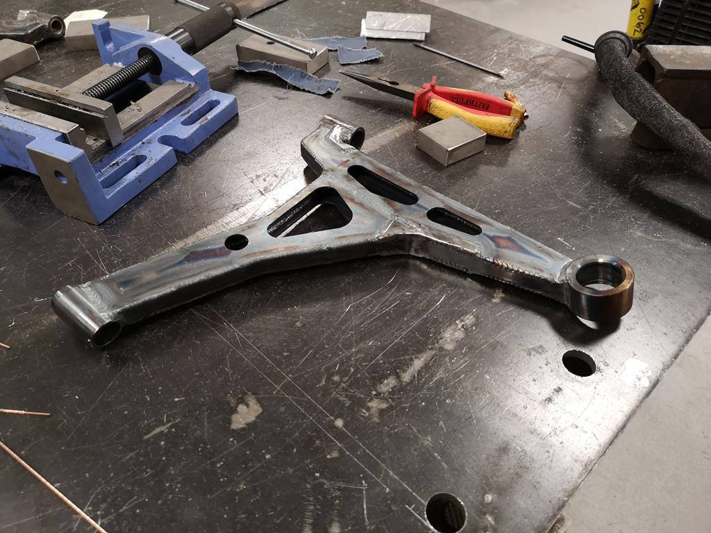 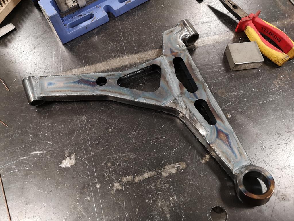 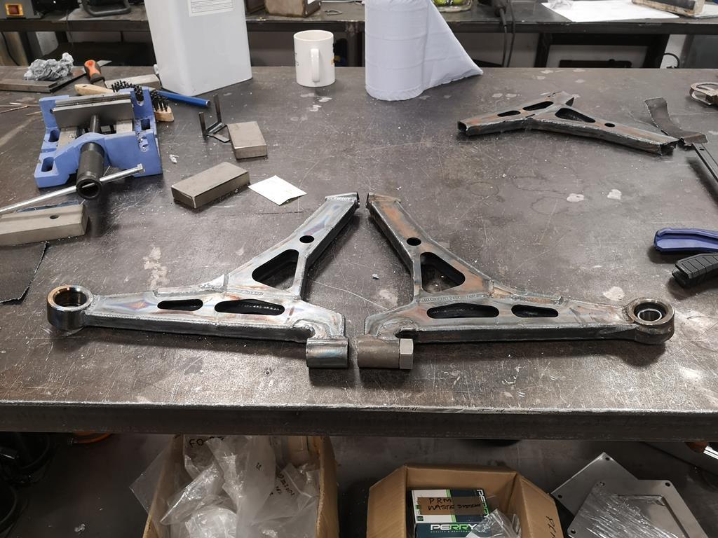 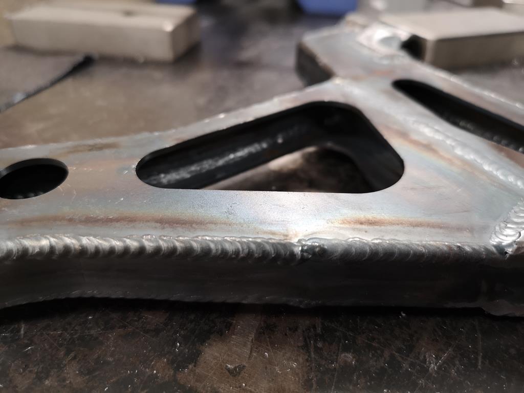 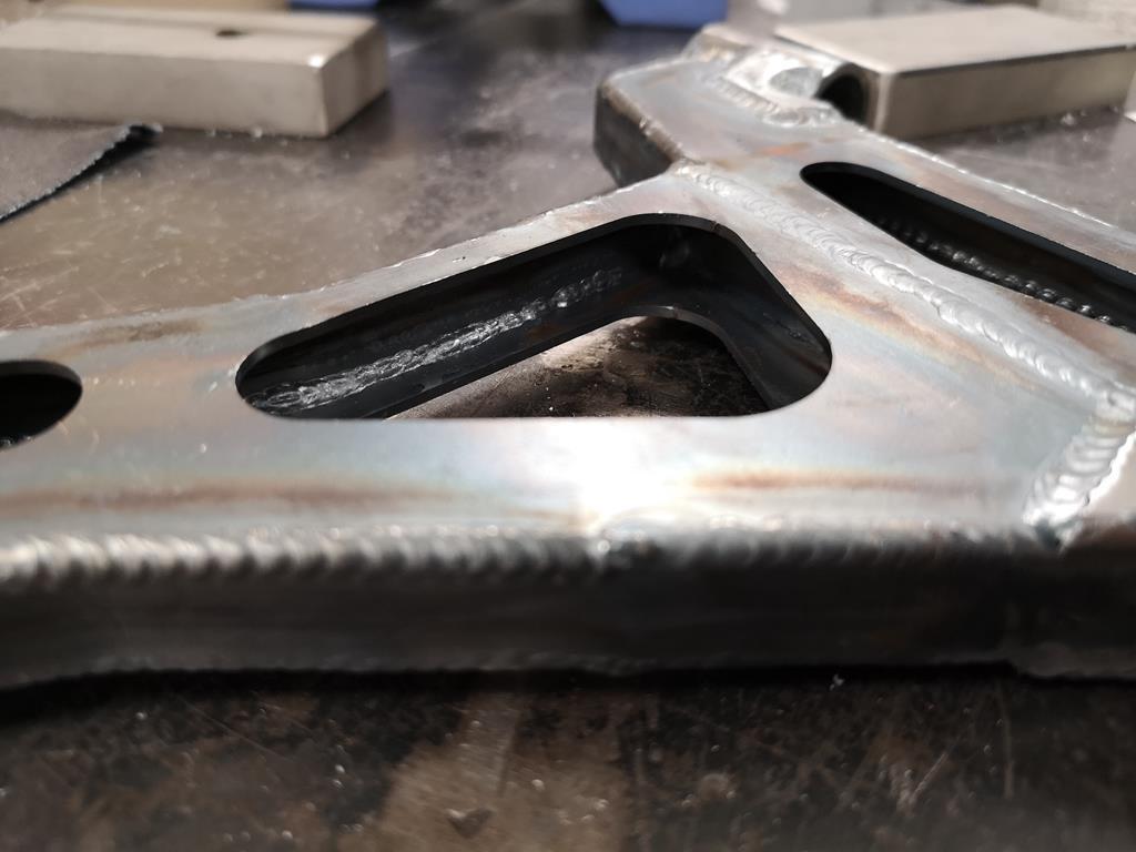 They're not the prettiest TIG welds ever, but I'm pretty happy that they're plenty strong enough. The downside is that the bearing housing for the lower ball joint has shrunk too much and I couldn't get the bearings to press into them! I'll be speaking to the machine shop we use at work to try and get them honed out to a nice press fit, but if that doesn't work I'm not sure what I'll do. My only thought was to turn up an aluminium slug to press in in-place of the bearing and remake them with that fitted while I'm welding the housing on, in the hope it reduces the distortion. I really do need to pull my finger out with it. |
| |
|
|
RobinJI
Posted a lot
"Driven by the irony that only being shackled to the road could ever I be free"
Posts: 2,995
|
|
|
|
Thanks Broady and Oioisavaloy. Could I ask where you get your laser cutting done ? Can't be a million miles from me (near Wells) but been quoted a stupid amount of money for a cut piece of 1mm sheet so time to investigate options. How's progress anyway? James All the bits in this thread have been done by Luffman Engineering, who are based just off junction 27 of the M5, so the wrong side of me for you unfortunately. There's a couple of bigger guys in Bristol (SSC Laser and Precision Profiles), but I don't know how they'd take to smaller orders. For small batches Luffmans and Laser Industries (Saltash/Plymouth based) have always been good to me. I suspect all of them will have minimum orders though, and I don't know how any are with selling direct to the public. I've always put a few orders through them through work before getting my own bits done, which probably helps with the price too. |
| |
|
|
RobinJI
Posted a lot
"Driven by the irony that only being shackled to the road could ever I be free"
Posts: 2,995
|
|
Mar 18, 2019 22:24:32 GMT
|
genuinely interested (not critical!) about welding cast steel steering knuckles, as i have to do it. To be honest I probably didn't think about it as much as I maybe should have, but after the fact I'm happy they're well stuck on there. Most importantly they do seem to be cast steel not cast iron; they're not brittle, they spark like steel and they give off curly 'cuts' of swarf, not just powdery chips. That's from memory though and I must admit I wasn't looking out for whether they were iron or steel, I'd just assumed that they would have used steel for a part like this, you've got me thinking I should double check on some of the off-cuts before I put them into any use. I did do a little test weld on the off-cuts and when I attacked it with a hammer it broke through the weld before the metal of the part. I kept a close eye out for any oddness around the weld but it seemed quite normal. On the back face the edge I was close to burned back just like I'd expect and the pool seemed to flow into the housing fine. I managed a bit more over the weekend. I stuck together the second upright: 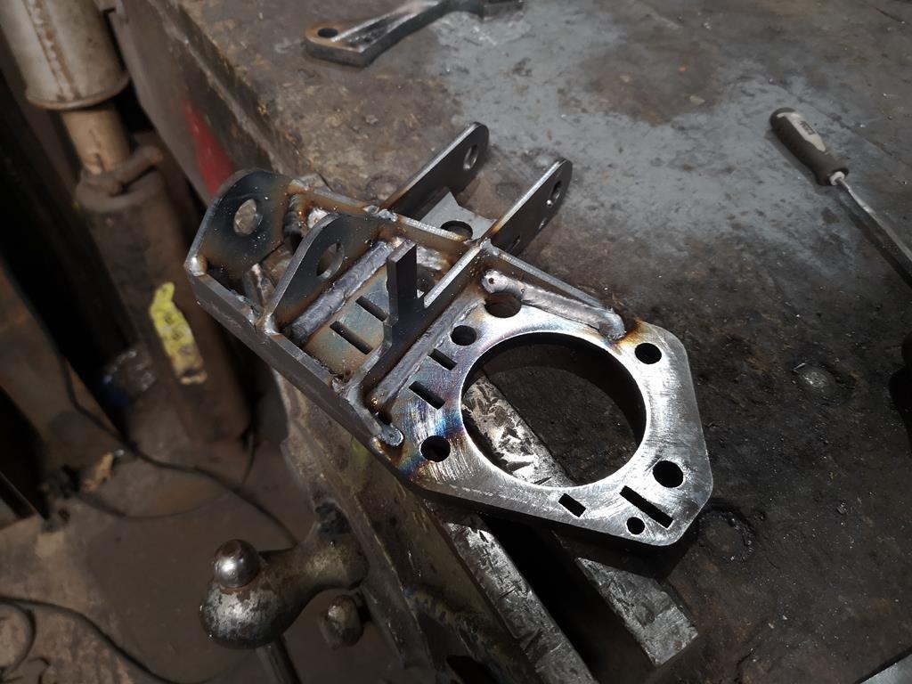 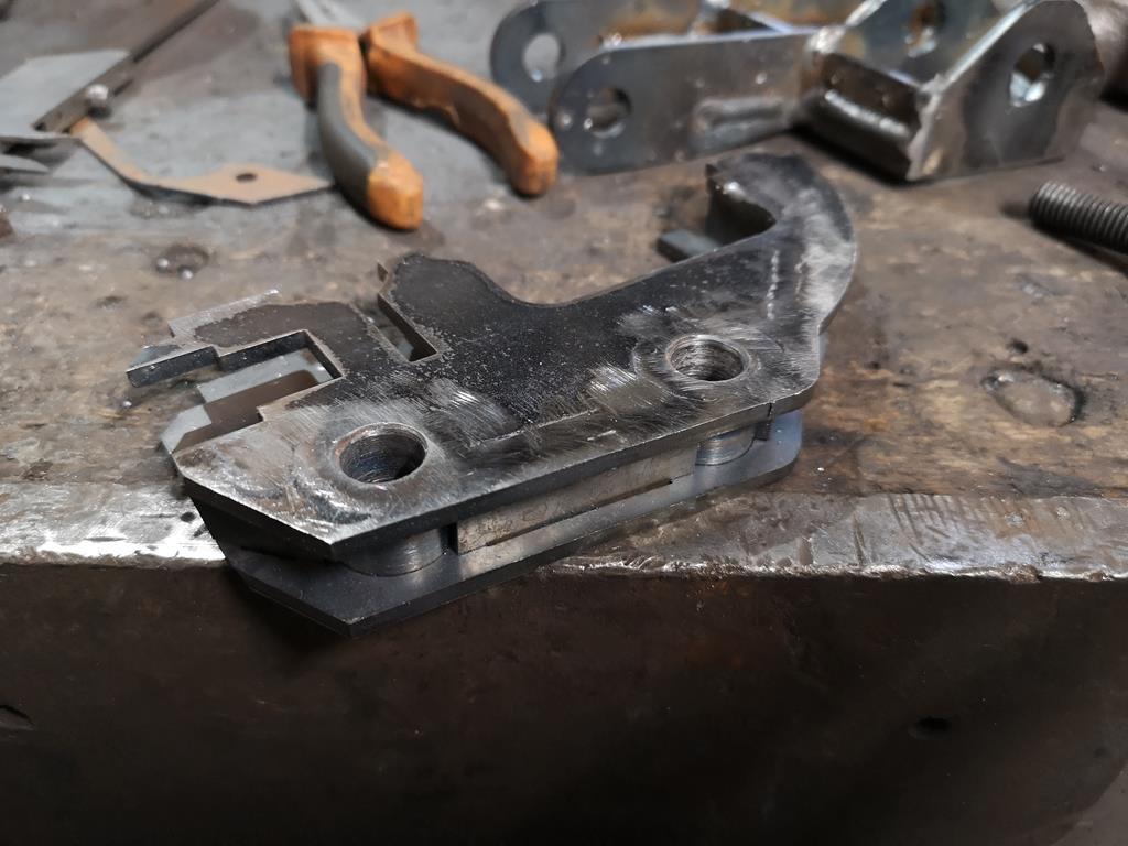 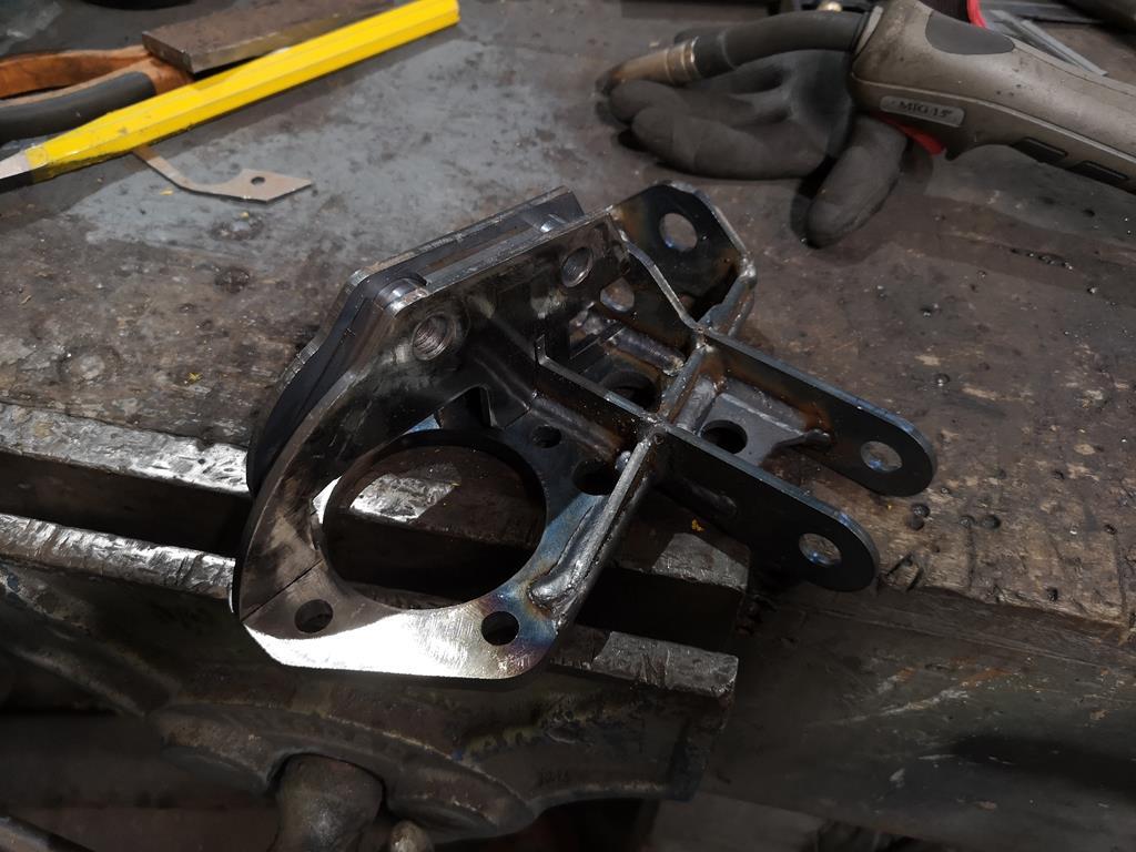 Then although I forgot to take any photos of the process I repeated the chopping up that I'd done on the other side to angle the balljoint to face the top mount. Then I cleaned up the track rod end adapters I'd made ages ago for the front subframes 'plan a' which was abandoned before this thread started. In the end these turned out to be right for the new set-up too. They're M14x2 one end and left handed 5/8th UNF the other end, with a hex in the centre and a fair bit of length to make up for how much narrower an escort is than a 924. A few seconds in the lathe with some emery cloth and they're looking good again. Finally I threw a little primer on them and uprights as well as the rear subframe to keep them from going orange:  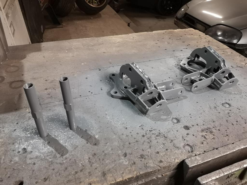 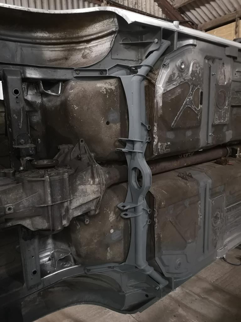 |
| |
|
|
RobinJI
Posted a lot
"Driven by the irony that only being shackled to the road could ever I be free"
Posts: 2,995
|
|
Mar 14, 2019 21:12:30 GMT
|
A little bit of an update: I finally managed to get some welding gas and decided to distract myself from the subframe briefly by getting the rear bearing carriers sorted. I had a pair of mk1 Audi S3 front uprights kicking around from an old project which I'd decided to use the centre section of as a pre-machined bearing housing. I did try and swap them for mk4 golf or audi A3 ones as the S3 items make a nice upgrade for the lower spec cars if they're lowered, as they have the geometry corrected for the lower ride height of the S3. Sadly it got to a point where it wasn't worth my time so I just butchered the S3 ones. The first job was to get the drive flanges out of the uprights to give me space to get in and cut off the superfluous bits. I thought the was a good excuse to finally make a press frame to work with the porta-power I own but never use. I'd grabbed some really heavy duty steel from the scrap bin at my old work (with permission) when some stuff got ordered wrong and thrown straight in the scrap. Some of it was used to reinforce the doorway of the unit and add some security, and the rest I'd kept with a press frame in mind. It's massively overkill for the 10 tonne ram of the porta-power, but it was free, so who cares. At least if I ever decide to get a bigger ram it'll be up to the job with a tweak or two: 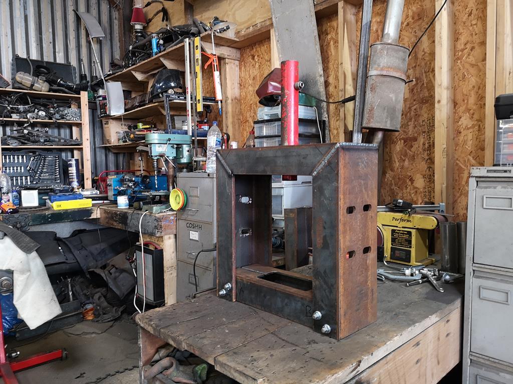 Which let me squish out the drive flanges to be left with a pair of these: 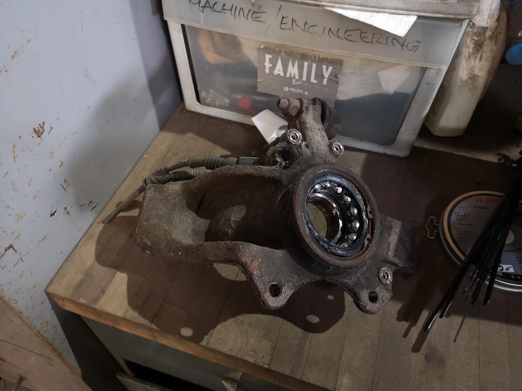 A while with an angle grinder later: 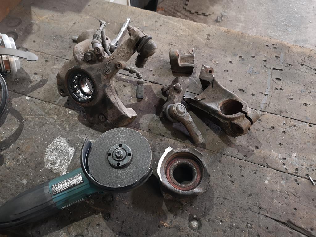 Then a while in the lathe to take all the unwanted features off, and just leave a lip at the rear edge 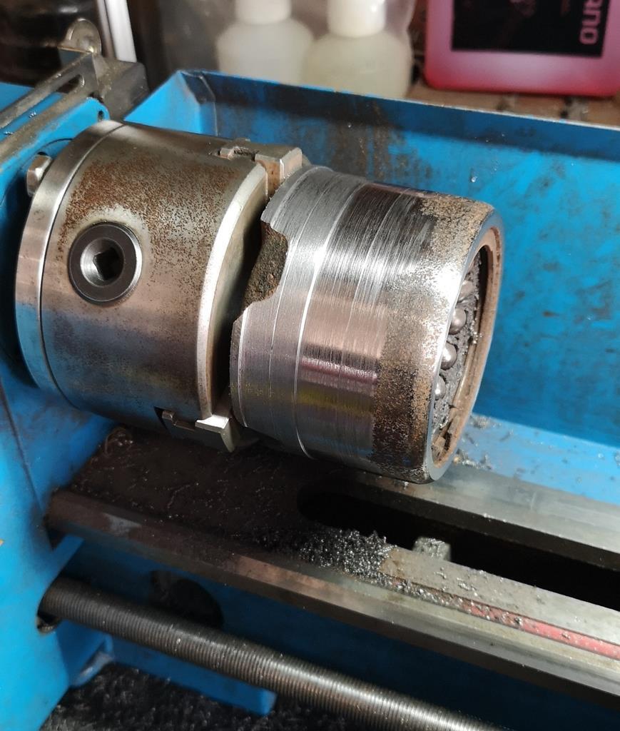 Tap a laser-cut profile over it up to the lip, weld the hell out of it, then press out the old bearings outer race, repeat the lot as a mirror image and you're left with a pair of these: 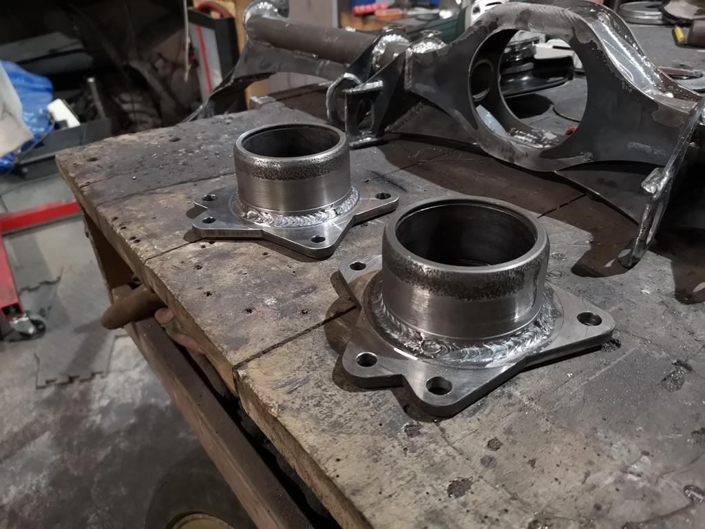 I left the bearings in until after the welding to try and minimise distortion and it seems to have worked, they certainly appear to still be round and parallel sided but I don't have much in the way of specialist bore checking kit. Once the initial corrosion was cracked the old bearings pressed out very smoothly, hopefully the new ones will go in similarly. The welds are actually kind of behind the bearing and I haven't taken it back very thin, so hopefully haven't messed up their shape. With those done, I welded the rest of the rear subframe before starting fun and games with a few strategic cuts and welds to get it back to the shape I wanted it, as the heat of welding all the top surface without it supported by the cars shell warped things a fair bit. In hindsight this was obviously going to happen, the design's very weld heavy and it was probably a mistake to weld one side in place and the other unsupported as it encouraged it to all banana pretty badly. I'm happy I've got it back how it should be now though and no weaker thanks to careful thought of where to make the nips and tucks. I should have got some shots while doing the tweaks but I was in a head-down-get-on-with-it mood with headphones on and didn't think to take photos: 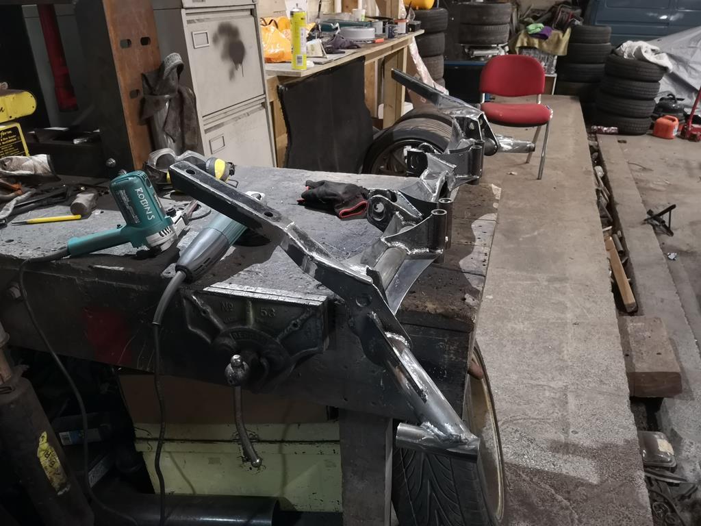 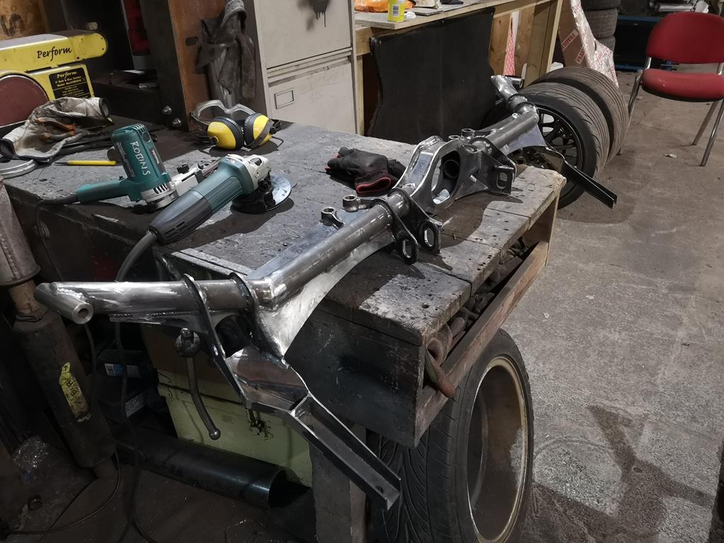 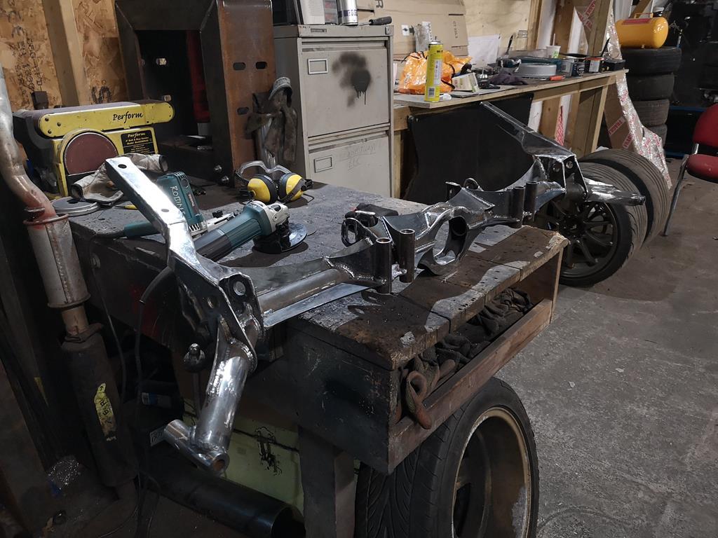 I think the end result looks quite cool, it's a shame it'll all be hidden under tatty bodywork. The next job for the back end is to make the bits that will join what I've done already: the rear arms. Speaking of arms, I also found time to send some of these off to our friendly local laser cutters: 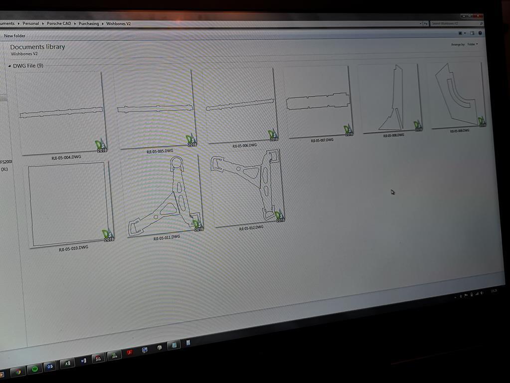 Which allowed me to collected this little lot earlier today: 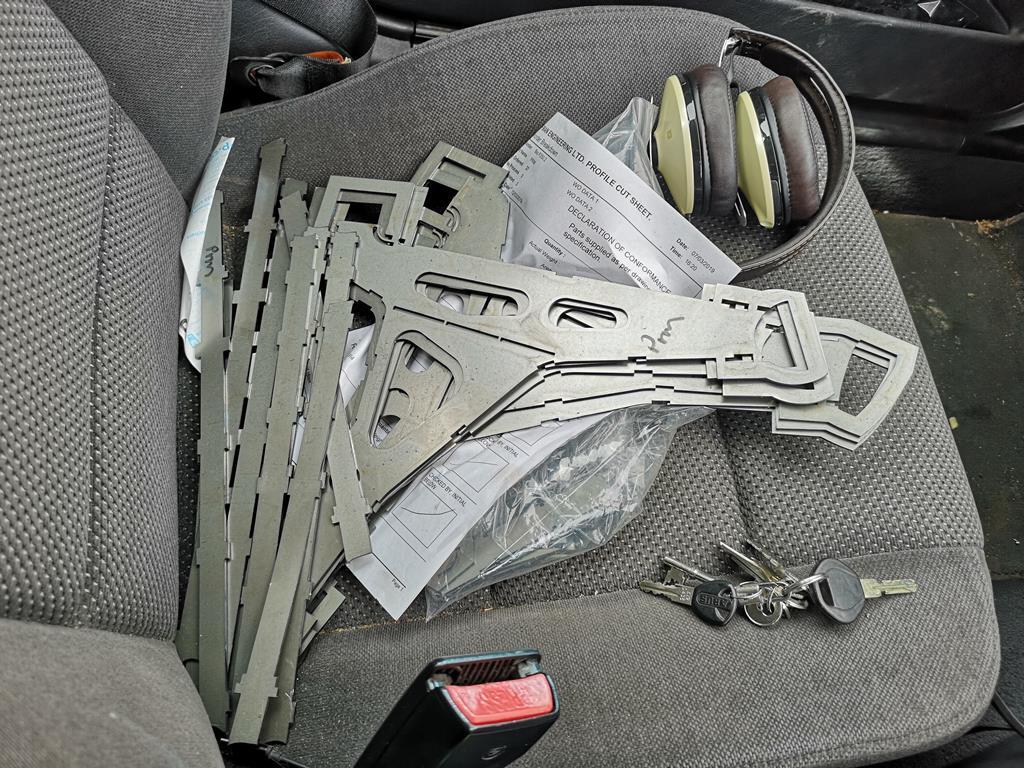 Those will let me have another go at the front arms, this time with the M18 lower ball joints matching the strut inclination angle from the word go, instead of the 5/8th ones mounted horizontally the old ones were cut to suit. The eagle eyed of you may notice that there's actually the parts of the 3 arms there. I thought this time I'd get enough done to have a spare in case anything goes wrong with the first. So I'm now 4 arms and one front upright away from being able to put the car down on 4 wheels, I'm genuinely excited by that thought, I think it's been 2.5 years since I first cut up the original front subframe and killed the possibility of having 4 wheels fitted at once! |
| |
Last Edit: Mar 15, 2019 7:50:50 GMT by RobinJI
|
|
RobinJI
Posted a lot
"Driven by the irony that only being shackled to the road could ever I be free"
Posts: 2,995
|
|
|
|
|
I've had some luck with SGS bottles too in the past. I think I'll be switching back from my BOC bottle to SGS soon as I'm using less gas recently and BOC have closed my local distributor making it nearly impossible for me to change a bottle outside my working hours. My past experience with the SGS stuff was good in terms of how it welds.
It's great to see some activity in this thread again!
|
| |
|
|
RobinJI
Posted a lot
"Driven by the irony that only being shackled to the road could ever I be free"
Posts: 2,995
|
|
|
|
|
With regards to sharp edges vs bell-mouthed intakes my understanding is that it depends on the condition of the air being taken in. Within an induction system, like an intake trumpet in an enclosure, the air is flowing as a result of pressure difference. Where as a 'ram air' intake* or a duct to something like brake cooling or a radiator is trying to capture an existing flow. They're quite different circumstances and need thinking about differently.
When the air's being moved by a pressure difference all the air around it is fair game, including the air to the side of and slightly behind the intake, as the pressure difference is capable of causing that air to rush towards the inlet. The best entrance design is the one that allows and smooths this flow, usually a typical bellmouth (just as nalesutol shows on his turbos intake trumpet).
Things change when your talking about trying to capture existing flow, rather than create new flow. In this instance we're trying to allow the air to maintain its inertia the best we can, and a bell mouth can cause a pile-up of air trying to enter it as its cross section decreases. Getting air to flow through it requires work (in the form of increased pressure or velocity) and will be at the cost of some air flow, if the goal is airflow it's probably more efficient to simple 'cut' a section of air out of the existing flow and allow it to continue as unimpeded as possible.
*Which design is most efficient is situational, and in the instance of a 'ram air' intake it would depend on whether the outside air's flow is great enough to keep up with the engines needs.
Looking at bikes and f1 cars I'd be guessing that their speed relative to their engines air consumption is enough that the designers have deemed the 'cutting' method to be the best bet, but the f1 cars look like they're on the boarder as their intakes appear to be a compromise between the two in a lot of cases.
Obviously things will change even more when you put the entrance somewhere without free flow, like above a splitter where there may actually be a high pressure to 'create' flow. Or if a brake or radiator duct has some sort of extraction an exit into a low pressure region.
I hope that makes some sense. I'm definitely no aerodynamicist, so this is just my understanding, but it makes sense in my head, and appears to match existing designs that real aerodynamicists will have spent time on.
I'm absolutely loving the Lotus by the way. Your mentality towards it all and the carbon work is awesome.
|
| |
Last Edit: Mar 3, 2019 11:13:29 GMT by RobinJI
|
|
RobinJI
Posted a lot
"Driven by the irony that only being shackled to the road could ever I be free"
Posts: 2,995
|
|
Feb 18, 2019 23:30:04 GMT
|
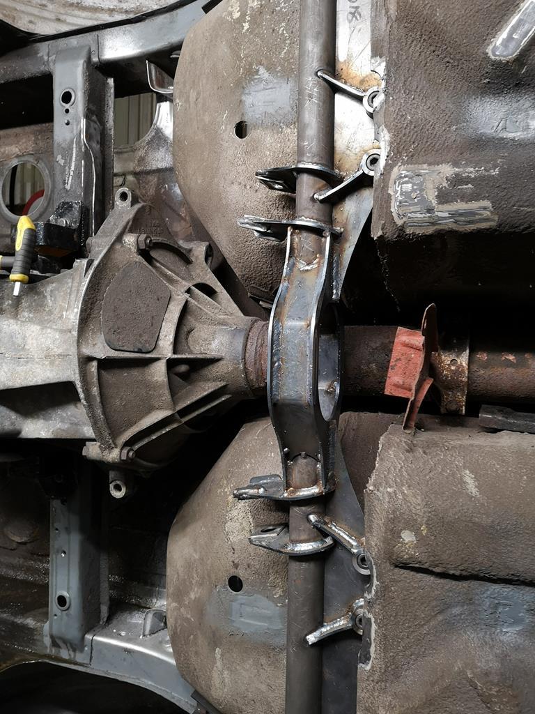
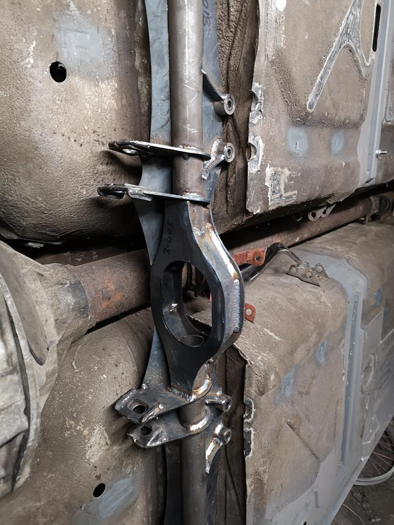
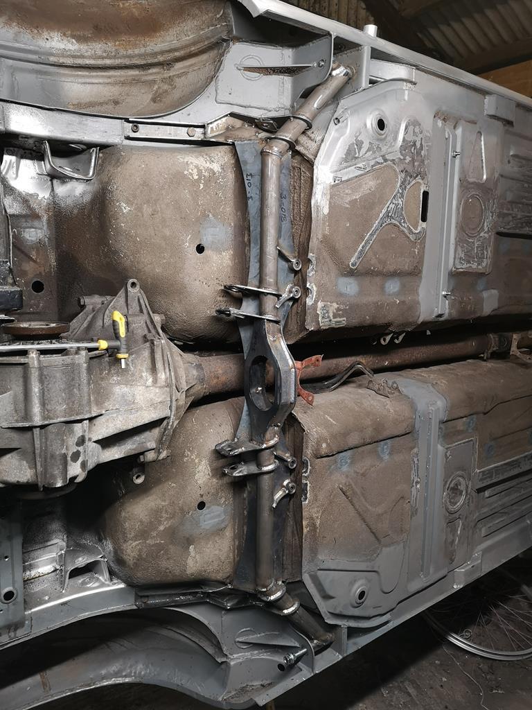
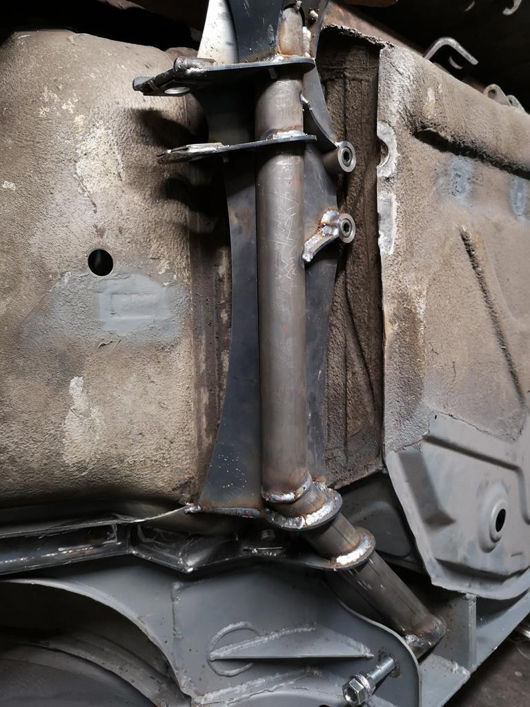
So a little progress. Saturday I popped out to work and gave my much neglected lathe a once over. I'd taken it into work to help with one or two urgent bits and help out my manager with a couple of things for his rally car. The lathes carriage had been getting a bit loose and the half nuts for the auto-feed were occationally disengaging unexpectedly. I'd also been meaning to modify it to add a proper carriage lock, as the only way to lock it when facing was to take the auto-feed out of gear and engage the half nuts, but it doesn't lock very solidly that way. Nothing to tell about it really, I took it apart, cleaned stuff up and reassembled it with care over the various adjustments. As for the carriage lock, a drilled and counter-bored hole in the carriage and a chunk of bar acting as a t-nut (in the channel the tail-stock locks with) seems to do the trick well. 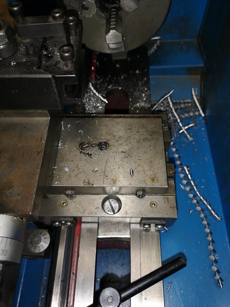 Excuse the bodged hex bolt with a slot cut in it! There weren't any long enough cap heads in the workshop and I know I've got some at my unit, so it's very much temporary! The lathe was definitely happier once it was back together, the carriage lock's great when facing and everything being tightened up has definitely brought it back from shonky-ness. Sunday I popped out to the unit, flipped the car 180 degrees and welded the opposite parts to those I did last weekend. I unbolted and removed the subframe and went to weld the top side but immediately ran out of gas so had to leave it there. 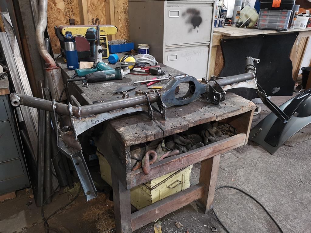 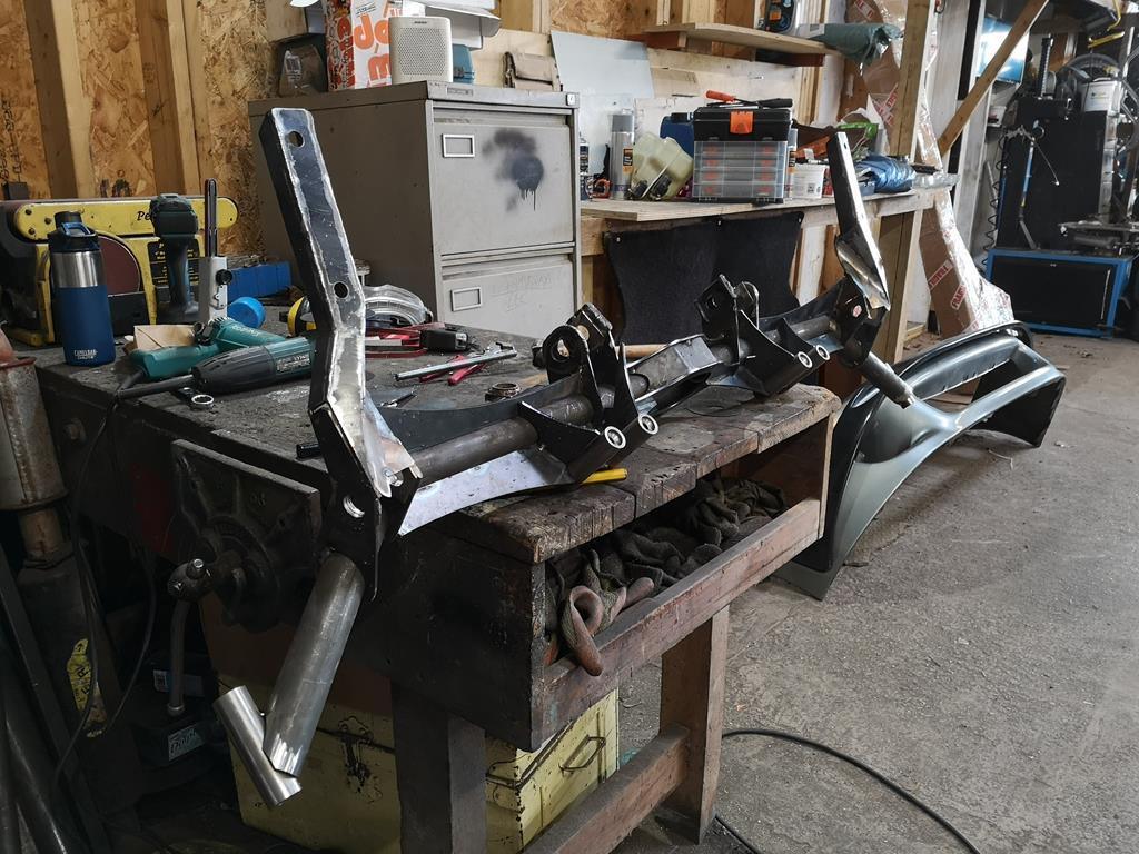 There's a couple of extra gussets (because clearly there's a lack of them so far  ) but other than the welding it's mostly there. |
| |
Last Edit: Feb 18, 2019 23:41:24 GMT by RobinJI
|
|
|
|
RobinJI
Posted a lot
"Driven by the irony that only being shackled to the road could ever I be free"
Posts: 2,995
|
|
Feb 16, 2019 23:46:37 GMT
|
Thanks Broady! So what is that big circle with the hole in the middle of the new subframe for? Driveshaft? John Ah, not sure how I managed to miss answering that in my last post! jonomisfit is absolutely right, it's for the exhaust to pass through. I really want to make sure that no part of the car sits lower to the ground than the floor pans or front subframe so the exhaust will pass through there to keep it up out of harms way. |
| |
|
|
RobinJI
Posted a lot
"Driven by the irony that only being shackled to the road could ever I be free"
Posts: 2,995
|
|
Feb 11, 2019 10:58:43 GMT
|
Stupid question: in your new rear subframe, there's the large center element with a big hole in the middle...what's that for? The factory torsion tube/driveshaft is above it. Thanks for the answers re imperial vs. metric hardward. It may be apocryphal, but I think I read that during the Concorde program, the French said they wanted Bristol/Rolls to re-engineer the Olympus engines from Imperial fasteners to metric. We can imagine the words used at Filton to say "ain't gonna happen". Thanks, John Haha, I can imagine that wouldn't go down very well! I'm definitely a metric guy on the whole, and very much think in metric, but if there's a product that suits my needs and is cheaper and more readily available than a metric one then I'm happy enough to put up with having to divide the odd number by 24.5. It is proving to be a pain with tools though, my selection or larger imperial sockets and spanners is pretty lacking! In an ideal world I'd love to design everything around a common bolt size/head size and use that throughout as it makes working on it going forward a pleasure but I it's a lot of messing around and time. If I do end up remaking anything (funnily enough I have plans to replace this rear subframe with something a little fancier in the long run) then I'll likely put the effort in, for now though I'm compromising to get it on the road as soon as possible. A rally car I lend a hand on has M10 fine bolts with a 14mm 12 point head on everything on the front end (sump guard, wishbones, subframe, rad support, top mounts etc..) and it's amazing to work on. |
| |
|
|
RobinJI
Posted a lot
"Driven by the irony that only being shackled to the road could ever I be free"
Posts: 2,995
|
|
Feb 10, 2019 20:39:00 GMT
|
|
|
| |
Last Edit: Feb 10, 2019 20:48:56 GMT by RobinJI
|
|
RobinJI
Posted a lot
"Driven by the irony that only being shackled to the road could ever I be free"
Posts: 2,995
|
|
Feb 10, 2019 11:00:15 GMT
|
My oh my yet more brilliant and well though out work. While checking you seating position I was going to say. Make sure you check it while wearing your bone dome. And there it is in the photo, so I can only assume you were already wearing it Thanks Broady. I was impressed with myself for remembering to take my helmet and steering wheel with me. It's the kind of thing I'd usually forget. With the seat in the position I settled on there's loads of headroom without the helmet, and even with my comedy sized 'XL' one on there's comfortable clearance. I managed to get a little time in Friday evening and yesterday and made a good start on the rear subframe (any further seat stuff can wait, getting it on wheels is highest priority right now.) I built a jig to locate the rear trailing arm mounts as they're not as easy to measure on the car as the front subframes critical dimensions were. The jig fixes their positions in space so I can build the rest around them. 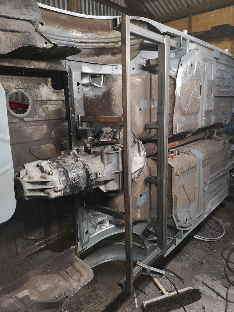 Then I've been adding in the laser cut parts along with a couple of lengths of tube with mitred ends: 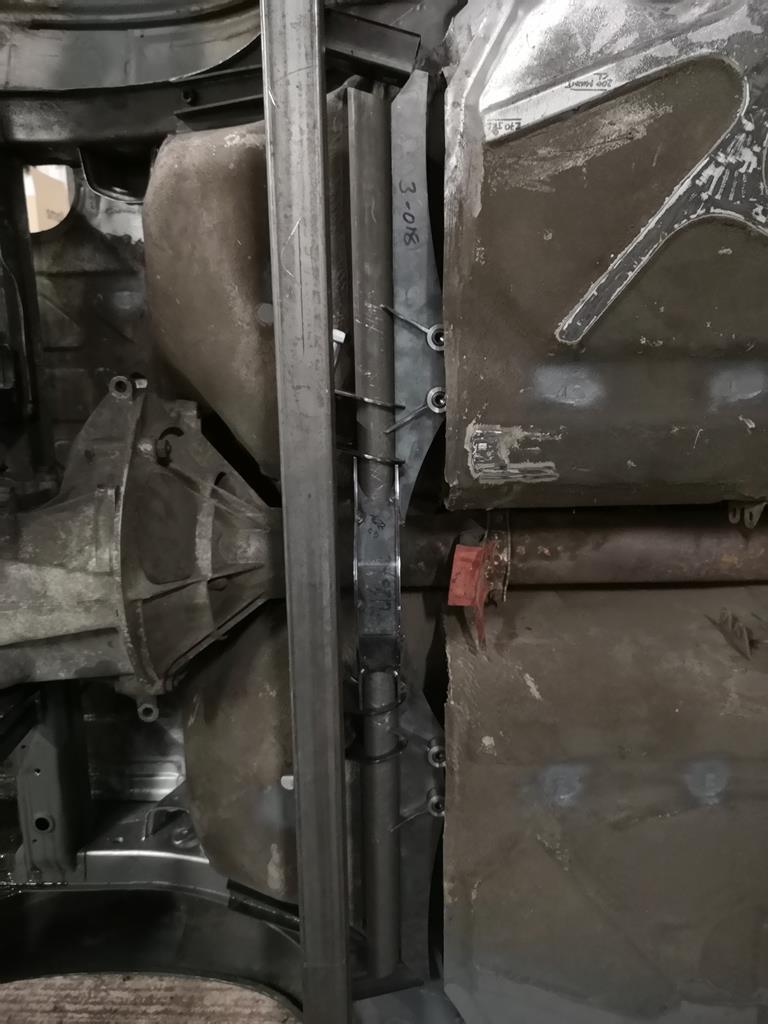 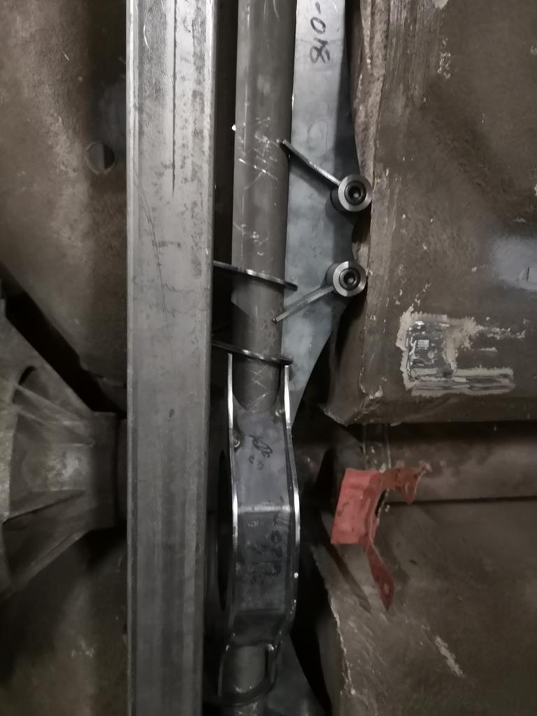 Unfortunately those terrible photos are the best I managed. Its hard to see much as the jig gets in the way. More soon hopefully. |
| |
|
|
RobinJI
Posted a lot
"Driven by the irony that only being shackled to the road could ever I be free"
Posts: 2,995
|
|
Jan 22, 2019 19:50:40 GMT
|
not sure what the point of the extension is? presuming bump steer modification, rather than roll centre. although not entirely sure its a "solution" to that. could just be packaging constraints for the track rods ? It looks to me like they've fitted different uprights and arms (possibly 911?), and fitted them with the inner pivot higher than the original arms. The steering arm's way higher than you'd need for the 944 racks position so they've extended the track rod down as much as possible within the confines of the wheel, but I guess that wasn't enough, so they've moved the inner pivot up too to simulate the rack being higher. It makes sense but yeah, that box section thing would play on my mind for sure. In fact the length of the extension on the steering arm isn't ideal either, its cantilever will be placing a large twisting force on the uprights steering arm, which with an aluminium part would have me worried about how many fatigue cycles it still had left in it under those conditions. Likely fine, but it's not how I'd choose to do things. (in fact it's not how I chose to!) I have seen formula drift cars running offset inner track rod mounts in a similar manner to that box section. They use them to push the inner track rod pivot closer to the axle line to get more lock before going 'over-centre'. (rack position's fixed in formula drift rules). They use a machined block that the original inner joint bolts into. Like so:   They look quite a bit more trust worthy than the box section items show above. I'm really enjoying reading this Nigel. Makes me wish I'd not bitten off so much with my plans for my car so I could be out on track sooner! |
| |
Last Edit: Jan 22, 2019 19:52:31 GMT by RobinJI
|
|
RobinJI
Posted a lot
"Driven by the irony that only being shackled to the road could ever I be free"
Posts: 2,995
|
|
Jan 21, 2019 19:43:56 GMT
|
Nice to get an update ! A little progress is still progress keep going spring is on the way. James Thanks. I certainly hope it is! Amazing project. May I ask, just out of curiosity, why you've chosen to use non-metric fittings for your new suspension components...are they less expensive? Great work. John Thanks! You got it in one. Decent quality joints are noticeably cheaper in imperial flavour. There's also the added bonus that they're always fine pitch UNF, where metric ones are often quite a lot coarser thread so fine adjustments easier. Well I did indeed head out to the unit after my last post and I'm happy to say the seats fit really nicely. No problems at all with clearance around the cage. In fact there's loads of space around them! It feels great sitting in there too. 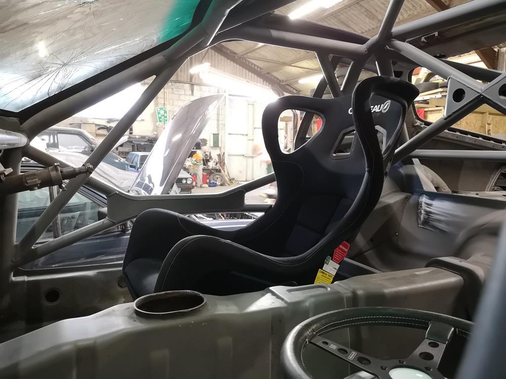 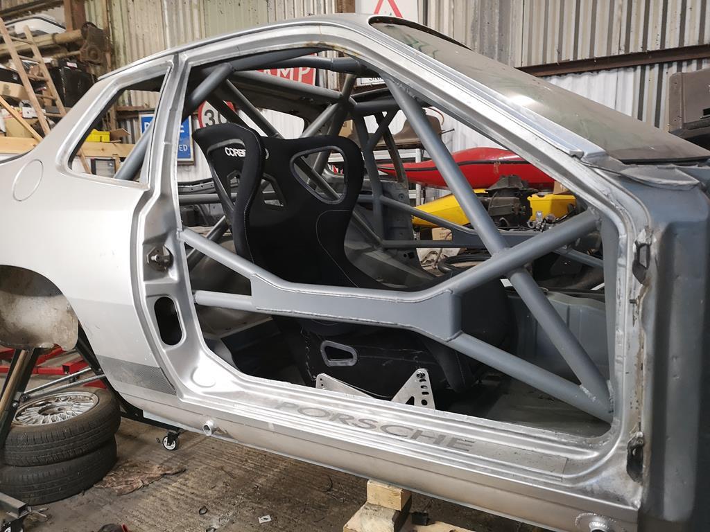 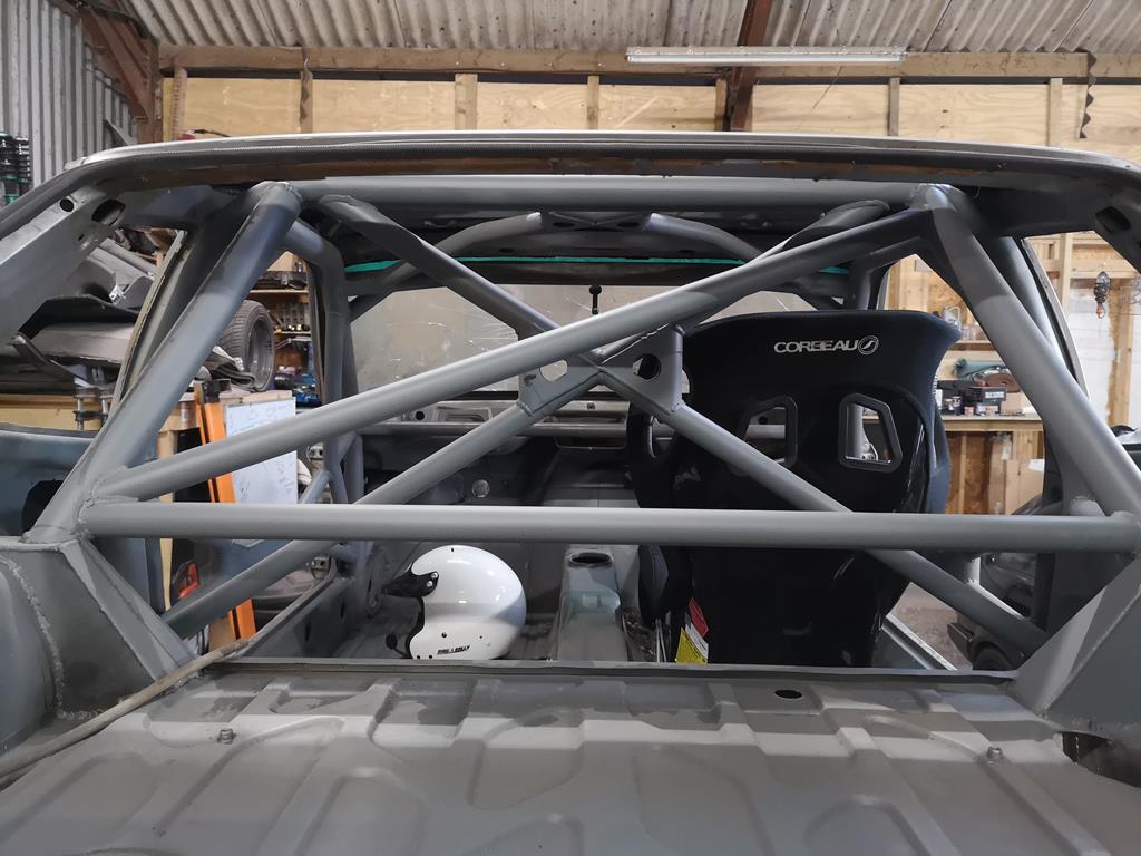 Handily they do fit my home-made mounts, but as I expected they need reclining a lot to get enough head room in the 924. My mounts don't have enough adjustment to get the seat lent back so much with the way they're bolted in right now. Annoyingly they'd be about right if I hadn't notched the front mounting cross member, so it may just be a case of un-notching that. 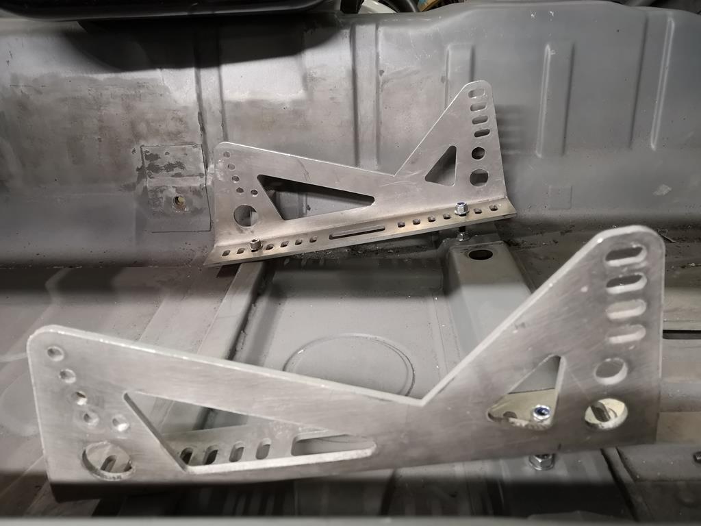 The pedals feel good but 924s have a very low steering wheel position, and sitting in there I think I am going to do something about it. It only needs to be raised 20 or 30mm, but I think it's worth doing now. I need to see where the wheel ends up once I've got a boss and quick release but I think I may need to extend the column a bit and I'll definitely have to kink the gear stick rearward a bit. As a bonus I think I can get away with the hydraulic handbrake position I wanted too. I'm not building this as a drift car, but hydraulic hand brakes are too fun to resist even in a circuit car. |
| |
Last Edit: Jan 21, 2019 19:44:31 GMT by RobinJI
|
|
RobinJI
Posted a lot
"Driven by the irony that only being shackled to the road could ever I be free"
Posts: 2,995
|
|
Jan 20, 2019 11:52:29 GMT
|
I have nothing constructive to add, more great work! Thanks! Solidworks is great. Quite easy to pick up and does lots of "engineering" stuff really well but still has reasonable surfacing and isn't bad for the more sculptural stuff. Love all the self jigging stuff, I was talking to a place that has laser cutting and cnc bending for tubes and wondered how well it'd do for a self jigging chassis as they said they can jigsaw all the tube ends so it only aligns one way Yeah, Solidworks is definitely brilliant as an all round package, and still has enough add-ons to touch on the more specialist areas half decently. I'd be a little cautions of using laser-cut tubes to self jig anything. I've done a certain amount at my old job, we got a lot of tube laser cut but didn't bother with much of the jigging. It can speed things up in a production environment, but the tolerances you have to allow to get it to go together (mostly because of the actual stock material, rather than the cutting.) tend to cause it to have enough slop to still need a jig or lots of careful measuring anyway. That's not to say it's not useful; having all the ends of tubes pre-shaped is invaluable, and adding a few locating tabs can be a great way of saving you from needing that 4th hand while you tack it, not to mention using deliberately miss-matched tab sizes to ensure parts will only physically go together in their correct place/orientation. Flat stock's great at self jigging as you can consider each joint to lock a plane of movement, which can let you design in a way that only goes together at the correct angles. I've found that around 0.2mm is the closest clearance you can get away with in a slot around a tab, anything less regularly involves needle files and a hammer to get in. It's no big deal for most stuff, but if you've only got the width of some 30mm box between your tabs that 0.2mm clearance is about one degree of slop in your connection. Having said that, it's great for setting positions along a length and I've no doubt you could use it knock a lot of time off building a chassis, I may even give it a go on my next project (which if all goes to plan will involve a lot of chassis building.) but I'd still expect to need a decent jig or chassis table. Jeepers dude, I really do need to sit down with a cuppa and go back through this thread... you've been busy! Thanks Mark! Kind of ironic that I've followed your comment about how busy I'd been with a long silence! I have done a small amount, but no where near as much as I'd like. I've not really got any excuses, I've just been slacking and struggling to find the time and enthusiasm over the winter months. I have however managed to get a wheel on the car! Look, it's almost like it's trying to be an actual car!  The strut assembly is now completely finished, although the wishbone's not and I still need to knock up a few spacers/shims/reducers for the rose joints and spherical bearings. The main point was to get it assembled and see if everything moved as it should. It didnt.... (insert a picture of a fox) I'd made a stupid oversight when designing the front uprights and placed the spherical bearing that's acting as a lower ball joint on a plane with the wishbone. This just about worked when just cycling the suspension through it's travel, the wishbone travels through around 20deg from full droop to full bump and with the right spacers the 5/8" spherical bearings I was using could just about handle that. (They're sold as having 8.5deg each direction, but with the right shims could do a touch more.) The trouble was, as soon as you steer the bearing's centre is being cantered over to one side, and suddenly you need a whole lot more articulation. 19.5deg each direction to be exact. There are 5/8" bearings out there that can handle this, but they come at a £62 each and their external dimensions don't match the housings I have, so I'd have to make new housings from scratch. The cost is the more off-putting of those two things, as going forwards these are a wear and tear part that will need replacing, using specialist high cost bearings isn't ideal, I don't want changing to ball joints alone to set me back £124! (The ones I was originally using cost £6 each!) The solution was to get a bit brutal. I hacked the lower portion of the upright off and welded it back on with the bearing aligned to point directly at the top mount bearing at ride height. The result being that as you steer the bearing is just rotating and not leaning over at all, leaving it's articulation to only deal with the suspension travel. While I was at it, I also ordered a pair of M18 bearings to replace the 5/8" ones. These are 'standard' bearings and come in at a very reasonable £13 and have a rated articulation of 15deg each direction, giving a much happier margin for error, as a bonus I could also buy an off the shelf housing and save myself a few hours on the lathe. Before I cut the bottom off the uprights, I made a little jig using a bearing, housing and some flat plate bolted to struts mounting holes. This ensured that when I rotated the lower section of the upright I didn't loose the position of the pivot point and mess up my geometry: The bottom of the upright bolted to the mini-jig: 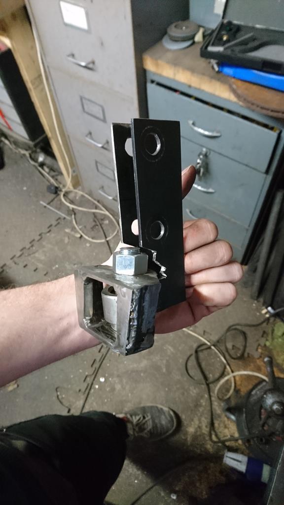 And the rest of the upright after it's removal: 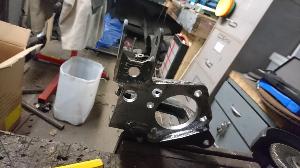 Bolted back up and set to point 18deg inboard and 8deg rearwards 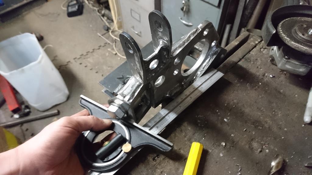 And welded back up with the strut and wheel bearing bolted to it: 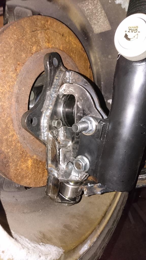 Even assembled with the old bearing this let me move the suspension through its full travel even at full lock, where before it was binding as soon as you tried to steer at all at the extremes of the travel. With the new bearing having over 5 deg more articulation everything should work nicely! 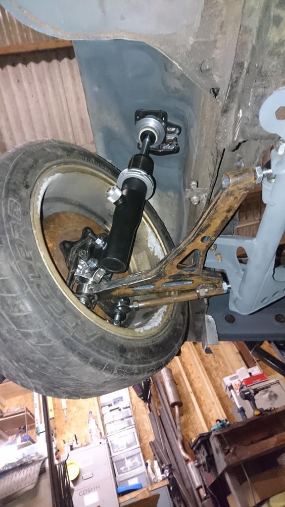 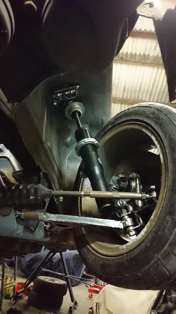 And this shot is what a lot of this has all been about! If you've been reading Nigel/pinderwagens Golfs excellent thread you'll be aware from this post why getting this all right is important. This is at ride-height, with ~80mm under the sills. I've moved the lower arms inner pivot point up around 40mm, and the bottom ball-joint down by probably a similar amount. I'm happy to have the wishbone's horizontal at ride height, it places the roll centre around 40mm above ground and gives a respectable (for a strut set-up) camber increase in bump/decrease in droop. 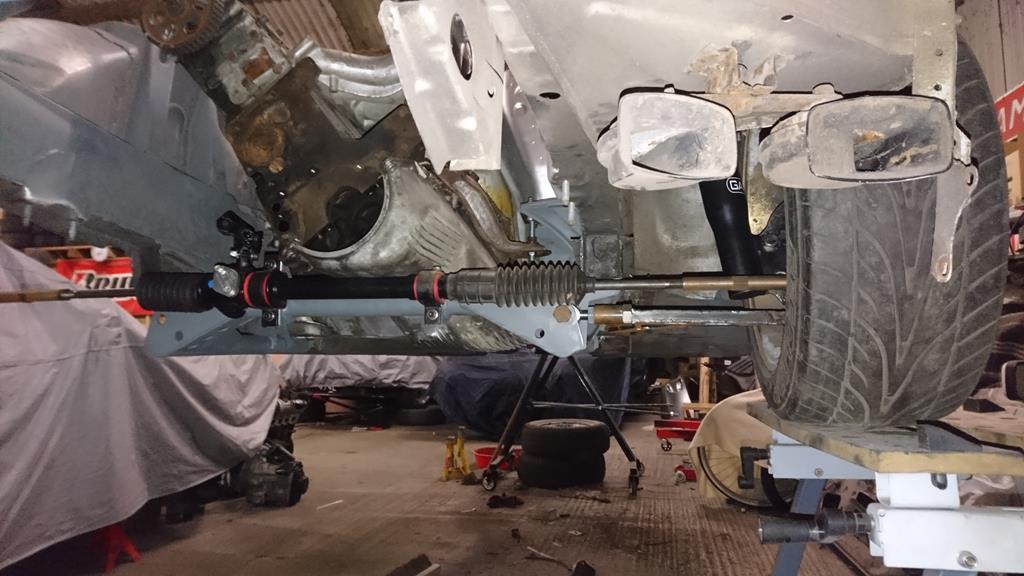 On a completely unrelated topic, I collected a good score off eBay yesterday (the seats, I've had the steering wheel a while): 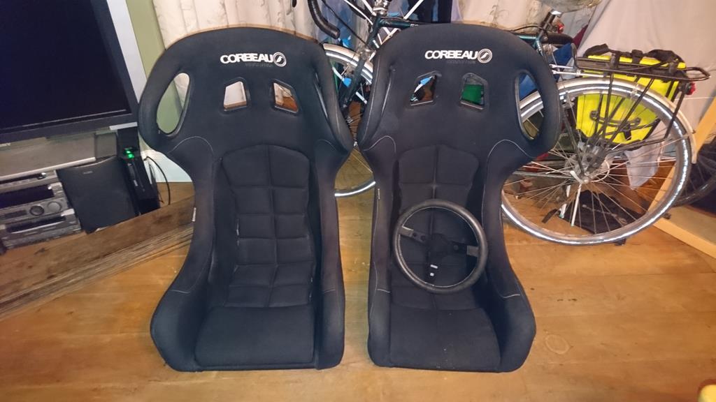 One pair of immaculate Corbeau Revolutions, one standard width for me, and one XL for the passenger side, as not knowing who's going to be in there it's a bit less restrictive for passengers. They're almost too nice for the rest of the car I'm hoping that a nice, tidy interior and engine bay will work well against what's bound to be a pretty rough and ready exterior. Anyway, that's enough typing. I've got a few chores to do around the house then I'll be off to test fit them in the 924. I'm at least a little bit worried about the width of them high up, fortunately although the 924's cabin isn't hugely spacious, it's respectably wide for an 80's car. |
| |
Last Edit: Jan 20, 2019 12:00:00 GMT by RobinJI
|
|
RobinJI
Posted a lot
"Driven by the irony that only being shackled to the road could ever I be free"
Posts: 2,995
|
|
|
|
Lasers are awesome: I placed the top mounts loosely together too, no real reason it's just satisfying making stuff look like it might work! [Picture] [Picture] Hopefully there will be some more progress soon. This self-assembly idea with tabs, cutouts and holes is frickin' awesome and I now need to steal it for my next build. Thank you Sir! Haha, thanks! It certainly takes a fair bit of the messing around out of putting these things together. If you're going to get stuff cut out by a computer you might as well get it to do as much of the work for you as you can! I see you get up to a lot of jiggery, I hope this is balanced with a suitable amount of pokery. I also like the application of many thousands of pounds worth of CAD software for a home brew project! Ive used a very different sort of CAD on my project, and it only cost me a pack of corn flakes Ah, plenty of Cardboard Aided Design has gone into this project too! Almost every bit of metal that wen't into the shell was mocked up in cardboard before cutting it out of the steel. I'm very lucky to have access to the kit that I do through work, this thing is the most expensive tool I've used on this project, quite literally by an order of magnitude: 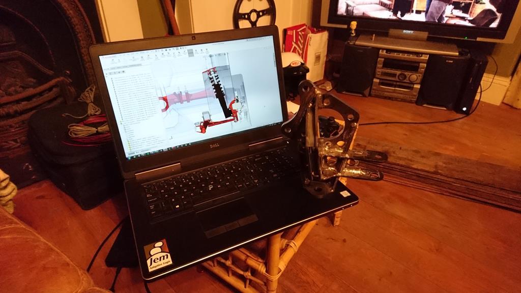 I'm even luckier to have a boss who doesn't mind me using this stuff for my own projects! Fortunately he's been bitten by the motorsport bug (rallying) so he's understanding of how addictive it is. On the other hand, I think he shares my view that doing this sort of stuff in my spare time is genuinely helpful to my professional development. Being the guy building what I've designed every once in a while teaches me a lot about where I'm getting stuff right or wrong design-wise. There's already been ideas I've come up with for the car that we've successfully used in work projects. That's not to say this is all out of reach for anyone who's reading this and doesn't happen to have access to professional grade CAD kit. There's some brilliant free packages out there these days which can be more than powerful enough for home projects. (If anyone's actually reading all this blabbering between the pictures, you may have noticed me mention that I used CREO Parametric to design the roll cage, and I'm now posting screenshots taken from SolidWorks. I can't remember if I've mentioned that my change of job at the start of the year, also involved a change in CAD package. I'm glad it did as while CREO worked well for my old job, SolidWorks is much better suited to the new job in my eyes, and as a happy bonus I find it much better for playing with car stuff.) I got a good day in at the unit earlier: My first job was to get the sump loosely bolted back on and work out how to raise the engine 20mm to clear the new steering rack position, so that I could bolt up the subframe complete with rack to check it was all good. The engine mounts that are currently on the car are the original ones that I did a horrible job of filling with polyurethane. The resin I ordered ended up taking two full days to cure, which is quite a bit longer than the 30 minutes advertised! As a result it managed to seep through every tiny crevice in the masking tape 'mould' and sort of absorb the masking tape, making a complete mess of things! I did the gearbox mounts 'mould' the exact same way but with a different brand of resin and they came out great! At some point I'll cast new polyurethane mounts, including new metalwork to loose the springs built into the original ones. For now though I needed to do something temporary to get the engine out of the way. I drilled three holes in some 10mm plate, welded some threaded rod into the central hole and bolted it to the shell with the other two holes. The thread-bar with a pair of nuts can now act as a height adjustable engine mount, like so: 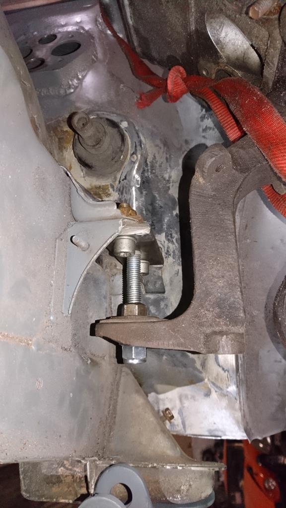 If you're not familiar with them, 924 engines hang from their mounts rather than sitting on them. It's a quirk of the torque-tube as under acceleration the engine tries to lift vertically upwards (rather than twisting like a traditional set-up does), so it makes sense to have the mounts in compression in this situation. With those fitted I bolted up the subframe complete with steering rack (and the not-good-enough wishbone) for the first time and was happy to see clearance around everything: 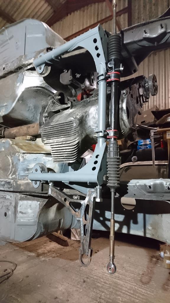 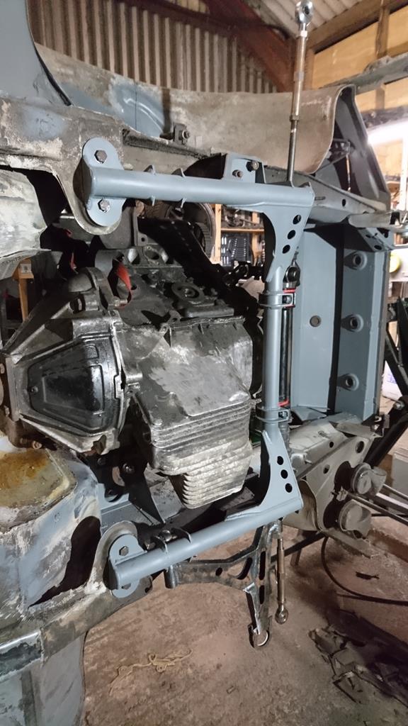 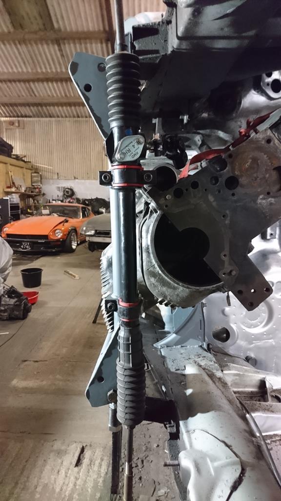 Next up I'm going to need some uprights sooner or later, now seems as good time as any: Starting by fully welding the bits that will be hard to get at later: 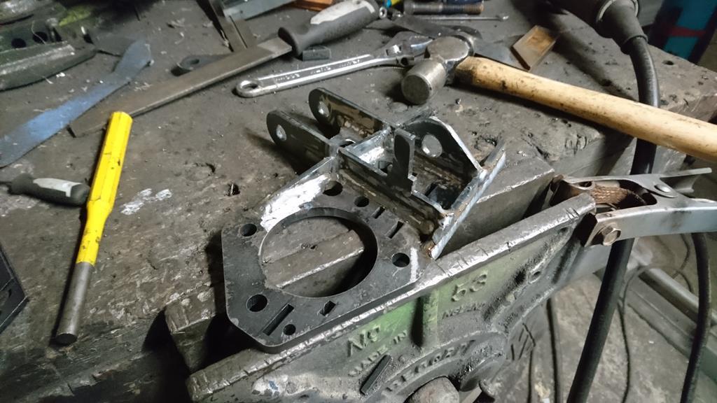 Then everything else: 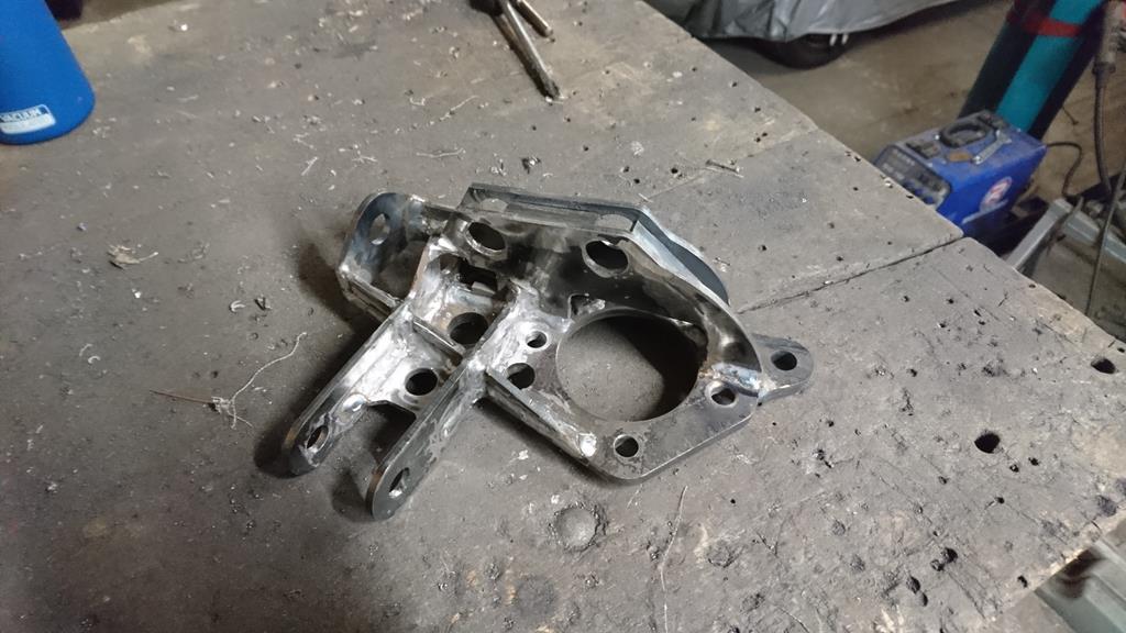 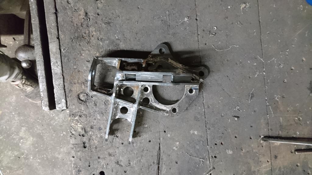 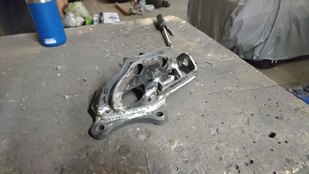 I'm happy with how that's come out.  I still need to turn down and weld in the crush-tubes as I've been meaning to check something on the model and only remembered to when I got home earlier. I'd been having doubts about my choice of 'neutral' camber. By which I mean the camber setting when the adjustment's set centrally. I'd drawn everything around this being 1.5deg but the more I thought about it, the more it felt like this might be a bit conservative and result in only one direction of the adjustment being useful. The easiest fix for this would be to turn down one of the crush tubes so that the hole's eccentric in it. Having checked the model again I've got plenty of adjustment for more negative camber even as it is, so there's no need to mess with things and next time I'm at the unit I can turn down the crush tubes and weld them in. Oh yeah, I mentioned the top mounts last time, well there's very little story behind them. For the section that bolts to the shell I just deburred and welded together the bits of metal that I already showed placed loosely together. The bearing holders went together easily with the laser-cut plate dropping over the turned bearing hosing nicely and sitting on the step I turned into them. I ran a chunky weld around them and then threw them in the lathe to get the faces nice and flat again as the heat from welding had slightly dished the laser-cut plate. That gave me this lot: 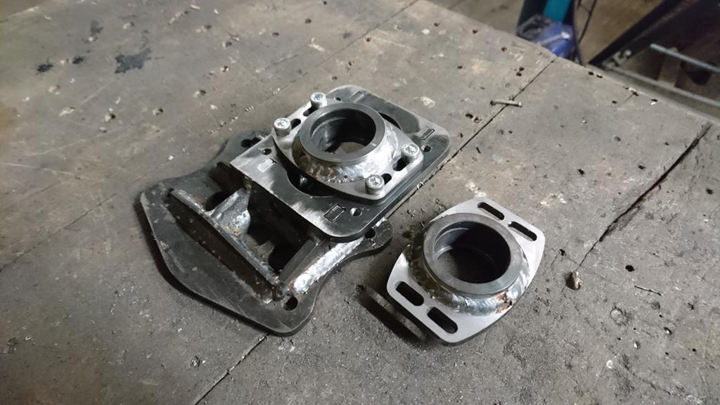 That technically gives me one of everything making me tantalisingly close to being able to get a wheel on the car! The issue being that while I've so-far made the nearside wishbone and upright, I've only made the offside top-mount. Woops! I've also somehow mislaid the Toyota Yaris wheel bearing I intend to use, then I'll need to knock up a few of these before it can actually be assembled:  The top ones are spacers for the lower ball-joint/spherical bearing, and the lower ones are the spacers/reducers for the top mount; internal diameter to match the M14 thread on the strut, external diameter to match the 3/4" spherical bearing in the mount and a wide base for the spring perch to but up against. I'm eager to get one side assembled as with the spring removed from the shock I can check that I have got the travel, steering lock and bump-steer characteristics I'm expecting. |
| |
|
|
RobinJI
Posted a lot
"Driven by the irony that only being shackled to the road could ever I be free"
Posts: 2,995
|
|
Nov 14, 2018 12:20:30 GMT
|
No big updates, I'll still catch up with the top-mounts when I get a bit more time but for now: I managed an hour or so last night and knocked the spatter off the subframe, then got some zinc primer on it before it could go orange:  |
| |
|
|
RobinJI
Posted a lot
"Driven by the irony that only being shackled to the road could ever I be free"
Posts: 2,995
|
|
Nov 10, 2018 23:57:33 GMT
|
jjeffries. Thank you John! I'm not quite sure if I'd want to know how many hours are in the car! I've learned a hell of a lot in the process and enjoyed doing it (with a few under-seal removing related exceptions) so even if for some (serious) reason I couldn't finish it, I'd still see it as a worthwhile use of my time! Hi Robin, If you have trouble with your gasflow of the tig torch, I suggest you fit a gas lens in your torch. It realy makes a huge difference. The arc stays more stabel, also the initial startup of the arc is more stable [Picture] Also the way you grind your Tungsten tip is very important, [Picture] hope this helps to get the welding finish you want  grtz, Peter Thanks for that, I've seen the lenses on youtube recently (A channel called 'this old tony' that I've been into recently, worth a look for machining stuff.) and thought they looked cool. The only issue with buying extra bits for the welder is it's not mine, it's works so ideally I'd be able to convince them to buy it instead  . As for tungsten grinding I'd been getting the direction of the grind right but I hadn't realised I was supposed to leave a slight flat at the end of it, I'll try that next time, thanks! broady, thank you! I was pleased with how the jigs worked out on the arms, less so on the subframe but I'll get into that in a second. Also, every time I've heard the word 'laser' in my head while writing this it was in Doctor Evils voice! Anyway, back to how some evenings in the last week have been spent: After that attempt at the first wishbone I've been concentrating on the front subframe so I've got something to bolt the arms to once they're done. This is all going to be MIG welded so I've been doing it at the unit rather than at work. Partly because I get on better with my MIG than theirs on thinner stuff (A 410 amp MIG is a little overkill for 3mm plate!) and partly because it means I've got the shell and other parts to hand. So I popped out to the unit with a boot full of laser cut stuff on Sunday afternoon. To continue making the best use of the lasers effort rather than mine, this is how the plate-plate corners were done on the front subframe where I know I'm going to MIG it:  The little spikes lock together and give just enough purchase to stop the plates slipping past each or moving sideways, while being small enough to run a weld straight over without ending up with a horrible lump. I like leaving an open external gap like this and welding these corners on the outside as I find it lets you weld a lot faster and with less heat buildup than putting a fillet down the inside would. I tacked these together and welded the thickening washer on where the lower arm's rose-joint will bolt on while it's easy to get at (urg, spatter, should have cleaned it more!): 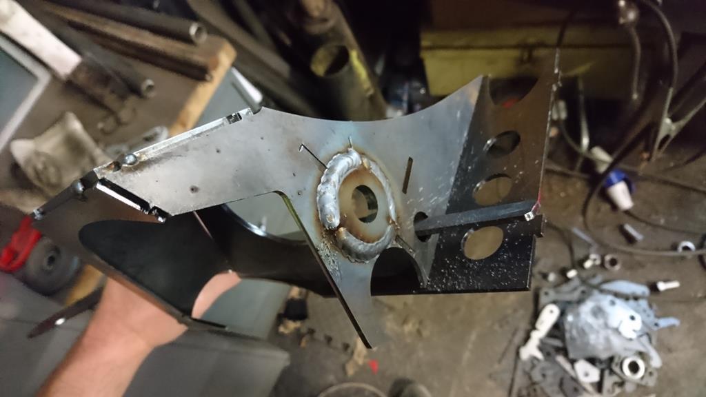 Next up, just going with the order I took these pictures in this is the next bit of jigging I had cut. The bit on the far right is part of the subframe, the plate that bolts to the shell where the lower arms rear bush used to bolt directly on. Everything to the left of that oval bit is just there to make my life building this easier! Jig Thing: 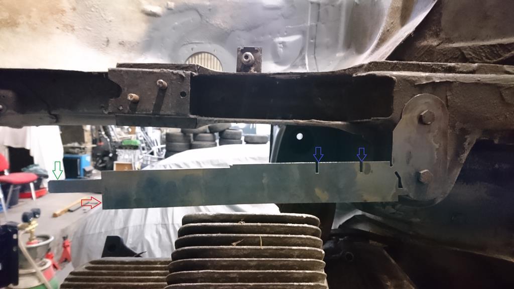 The pokey bit with a green arrow against it goes through a pair of holes in the front of the frame, just for a bit of location. The flat with the red arrow butts up against the back face of that plate I welded the thickening washer to in order to set it's distance forwards. The two blue arrows are showing the slots that will locate the two tabs the rear pivot for the lower arm bolts between. If you're wondering whether it was really worth paying someone to cut this out of solid steel with a big angry laser just to save me taking some measurements this plate cost £1.95+VAT. I call that a no-brainer! While we're on the subject of how cool lasers are for making tedious jobs easy: Scalloping angled plates to slot around a tube nicely is a pain in the backside, so it's hugely satisfying to slot some steel together, bend one side down to an awkward angle until it hits an angled plate, tack it all together and look down it to see this: 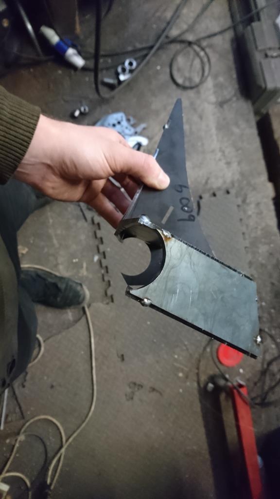 Offering up an off-cut of tube (the tube in this front subframe is 1.5" x 3mm tube left over from the roll cage) I couldn't really ask for a better fit: 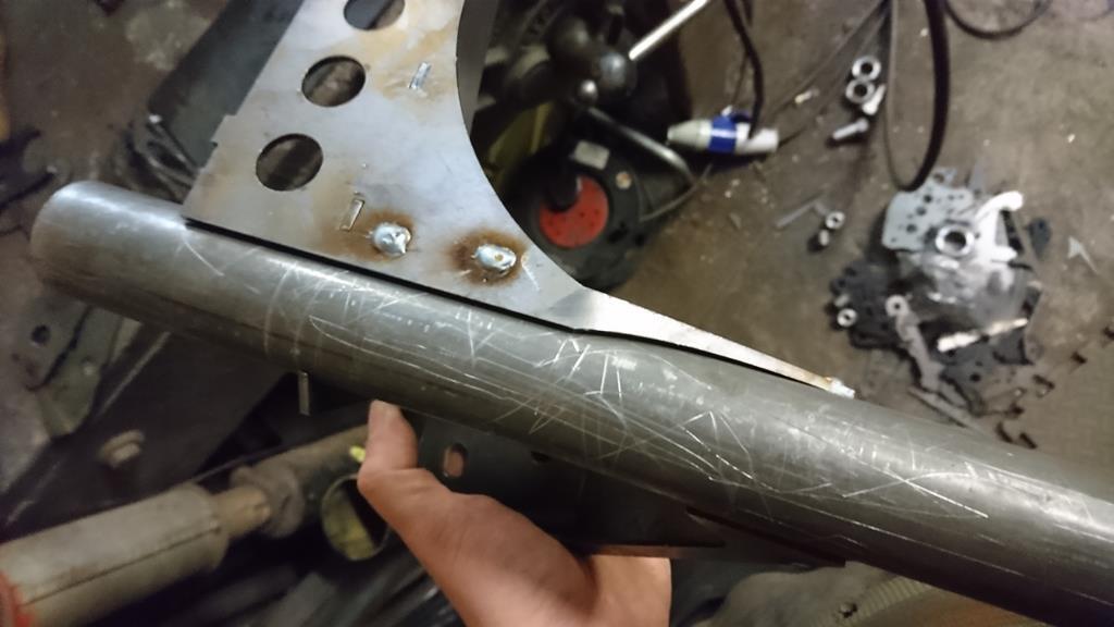 So, some appropriate lengths of tube cut and trimmed to fit nicely and a load of welding later I was left with a pair of these: 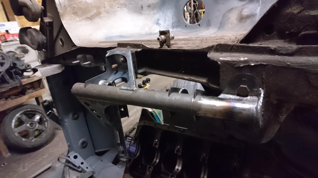 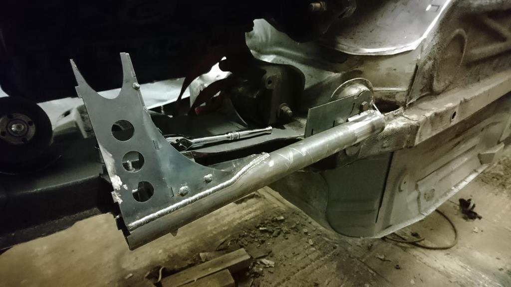 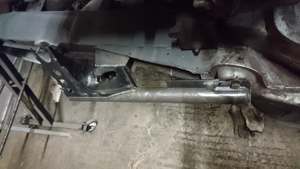 You can see I've cut away the front half of those jig-thingys. Once they'd done their job of telling me where to put that front tower-y bit relative to the rear mountings they were in the way of finishing the welding. I fully welded all this lot at this stage to get the heat distortion out of the way early, like, early enough that I haven't linked both halves together yet. The frame's basically a big 'U' shape and all this welding would have tried to make it a big triangle rather than the square-with-a-side-missing I want it to be. This didn't work out quite as I'd have liked unfortunately! Time for some more jiggery: 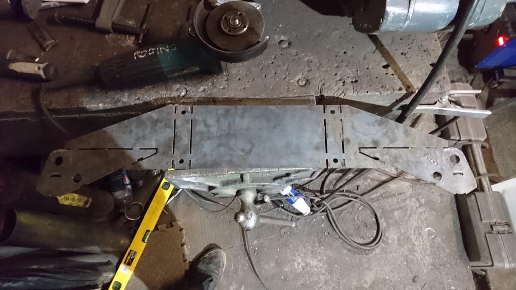 This was £6.07 worth of laser-d up goodness. I only want to keep the 4 small parts but for that price it seemed silly not to keep them fixed in space relative to each other. The two narrow bits in the middle will be the steering rack mounts while the end triangle bits are the front plate of the front pivot for the lower arms. A tube runs across here with it's centre-line on the top edge of the triangles. Like this:  At this point I did away with that plate, as I'd already used it to fix the bits that fix to it. I think this is where I cocked up a bit, but it left me with these three building blocks of a subframe: 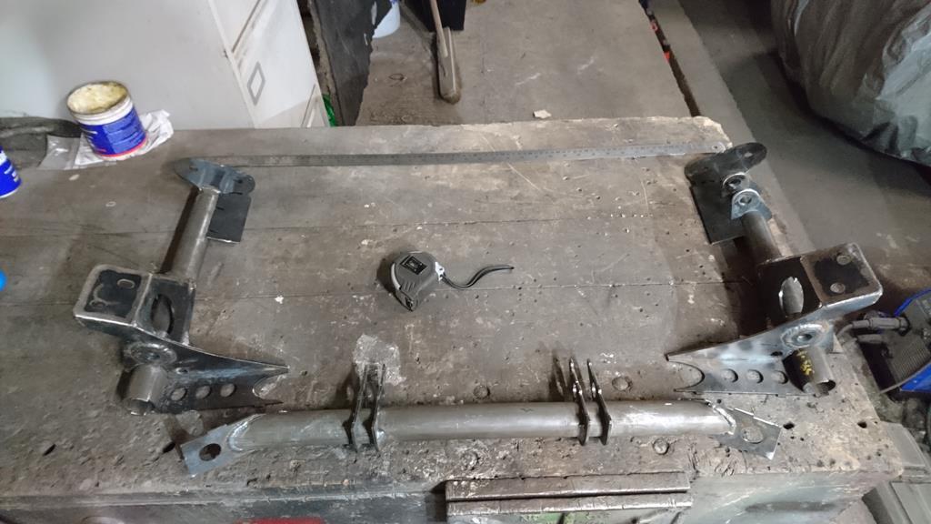 Which fit together like this: 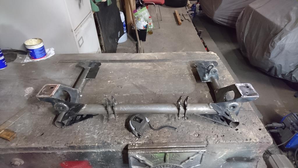 This is where I started having problems. This lot slotted together nicely right up until I bolted the two sides to the car then added the cross-member. It just really didn't want to go in place with all the tabs linked in and the bolts into the body. After lots of faffing I went home for the day. Tuesday evening I thought I'd take a different approach. I laid it out on the bench with some box g-clamped across the back to close it into a full square and hold the rear mounts the right distance apart. This worked according to the tape measure, and steel-rule, and a big square. Weirdly the cross-member didn't seem to fit too badly now. I cautiously welded it up and offering it up to the car it seemed happy except the slotted holes I'd put in one side of the mounting were being used to their fullest extent. (for ease of installing over the studs, one side were close tolerance, the opposite slotted). Hmm.. not ideal but livable (I think, but it will eat away inside me! Spoiler alert: I've fixed it.) Time to use those final bits of the first jigs, the bits with the blue arrows. I'd already welded the thickening washers to the mounts when I did the other front pivot points plates ones, so it was just a case of wriggling them around the tubes into the slots which fixed their front-rear position nicely. Their up-down was fixed by them encapsulating more than half the tube but they were still free to rotate. To get around this I fixed their distance apart by drilling some box section with two 5/8" holes at centres matching the tubes centres and bolting them to it: 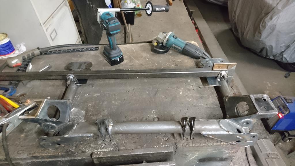 They were however still free to rotate around the tubes in synchronisation, offsetting both mounts to one side or the other. To deal with this I chopped the end off the box section 19mm away from the first bolt hole. This let me drop a square over the end of the box and know that when it was touching the tube the bolt hole was centred over the 38mm tube. 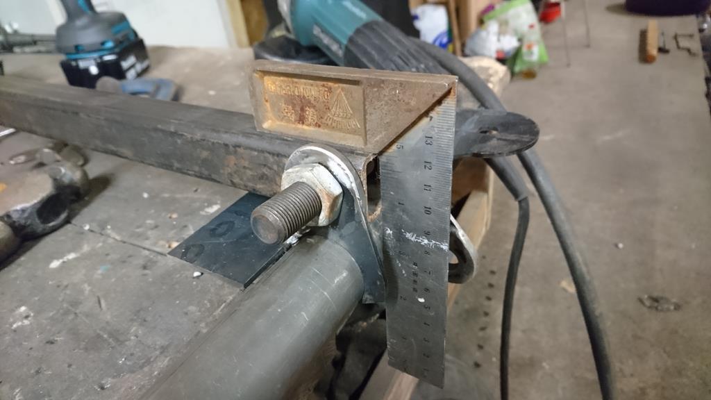 A little welding later this left me with this very nearly complete subframe, but a few steps back were in order before the final big stride farwards: 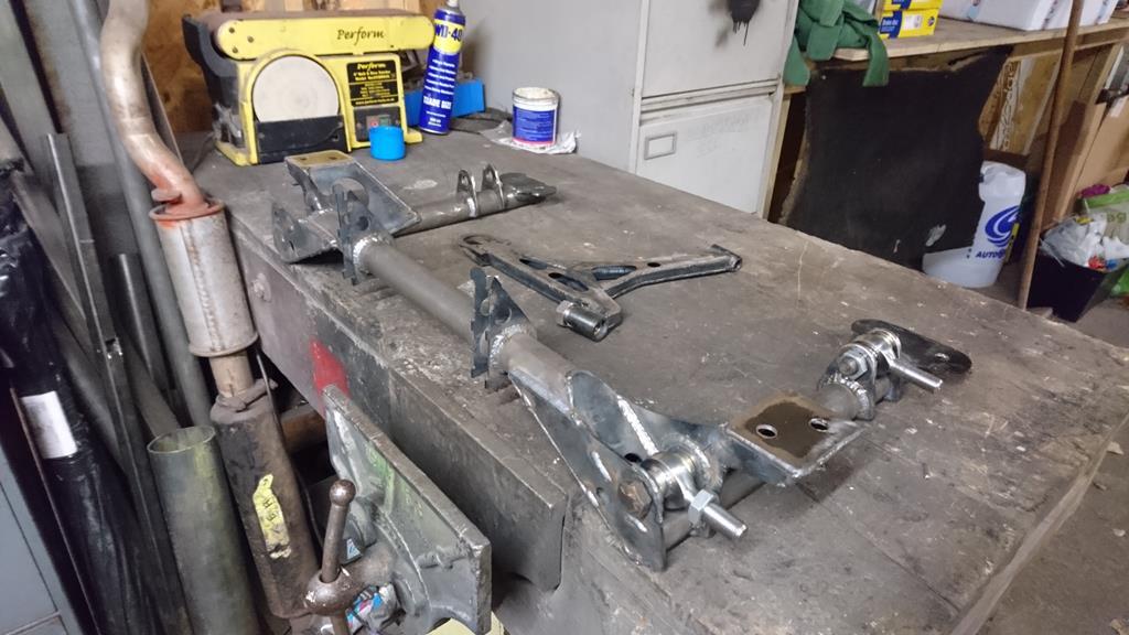 I offered up the steering rack only to find the mounting points on the frame are too close together by about 3mm. Cockrells. It was in the realms of squishing the poly-mounts into place and calling it a job done but it's a steering rack, it should fit properly, like, properly properly, not just properly enough. Foolishly I'd drawn the rack mounts from an autoCAD file I'd found online for a mk2 escort rack; apparently I should have checked it against the real thing like I'd always intended to but forgot to. As for the mounts themselves, the bolt holes in the laser-cut plates were way out!  It dawned on me that as the CAD model I'd got the spacing from didn't show the mounting brackets, just the space on the rack they clamp around, I'd drawn these mounts without measurements. I'd had a guess at the sizes to get a general concept into the design, to be refined later. Later never came. Amazingly I'd actually got the height and width of the mounts spot on in my guess so it wasn't as much of an issue as it could have been! The hole spacing was an easy fix as the plates they're in are basically just rectangles so cutting and drilling some new ones from fresh plate would be a 2 minute job. At this point it was getting rather late and the landlord stuck his head in to ask if I minded locking up the compound the units in if I was staying much longer so I thought it was a good time to call it a day. Heading back out to the unit on Wednesday I didn't yet want to tackle the spacing of the rack mounts so I started on another more expected issue: I knew the left hand steering rack mount and bracket was going to foul the sump, but didn't know how to rectify it in the CAD model without the proper measurements of the rack. It was something I thought would be easier to deal with in reality than the model so I got both mounts made the same to give me a starting point to cut up. Turns out I was right and it was a quick and easy job to chop it up to give more space above. I basically blow-torched and flattened the top 'leg' of the left hand rack clamp so it was laid back horizontally instead of straight up, then folded the plate it bolts to and chopped the top off the side plates of the mounting-bit on the rack. The blow-torching and bending of the clamp is what put me off computer modeling this mod; I wouldn't know the final position of the hole until I'd done this. I could have measured the radius on the clamp and calculated a theoretical end position using k-factors and such, however I'm as happy holding a grinder as I am a calculator and I thought the time was better spent in the real world than finding a theoretical final shape! After a little grinder swinging and metal melting I ended up with these two correctly shaped mounts. All holes in the right place but 3mm too close together: Right mount, as designed with an unmolested escort clamp:  Left side, with extra space-for-activities above it:  (Ignore the way the rack's fitting nicely in these photos, the photos illustrate the point I'm talking about but were taken later than this point in the narrative, at this point the mounts were still too close together. Spoiler alert, these photos are a hefty clue that I've fixed it now.) Now in these evenings I've been working with only the lasered jiggy-bits for measurements. The laptop and CAD model were at home or on my desk at work so I was just checking things were square and hoping the jigs did their thing. After consulting the CAD model a happy twist of fate revealed its self: I'd also cocked something up while sticking the cross-member to the side bits when I removed the jigging plate a bit early! As a result the wishbone pick-up points were 2.5mm too close together. This left me with steering rack brackets 3mm too close to each other, pivot points 2.5mm too close together and mountings onto the shell at the edge of their slot (the edge that let them move further apart.) The solution was obvious if a little brutal, I needed to chop the thing in half and add about 3mm: Friday evening I was feeling ready to face my own failures so as the MCM boys would say, 'chopped': 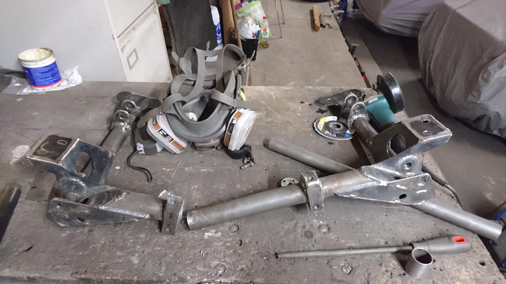 Sleeved: 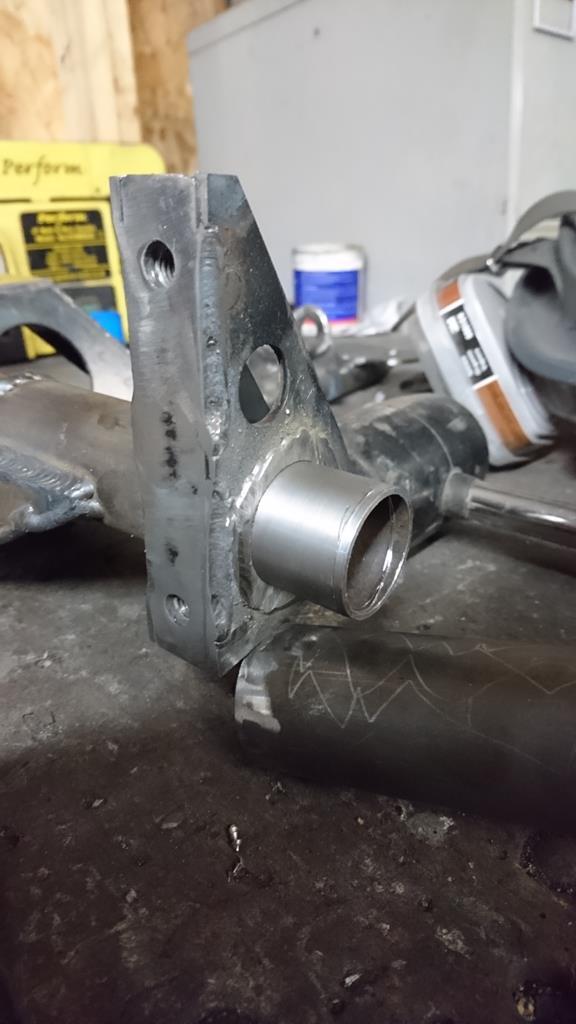 Slotted back together: 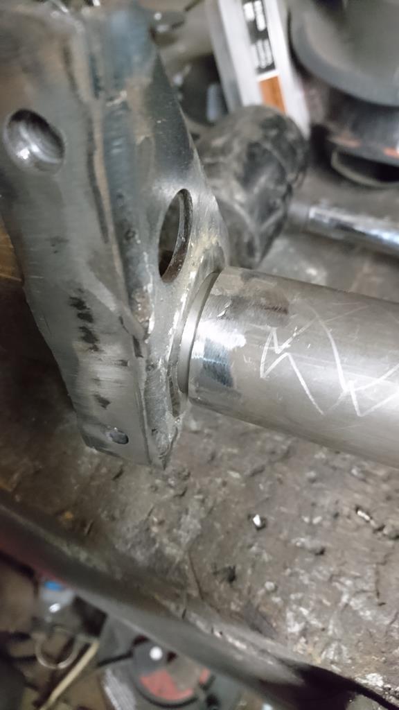 Predictably, this threw up the issue that pushing the front of the subframe wider also pushed the rear wider, the trouble being that the rear portion fitted nicely and was problem free, so in the end I did a symmetrical cut and sleeve on the other side. This let me add the width up front and tweak the angle of the cuts to keep the rear mounts in the right places. The end result after some MIG action was a subframe that both fits the shell well:  And a steering rack bolts to: 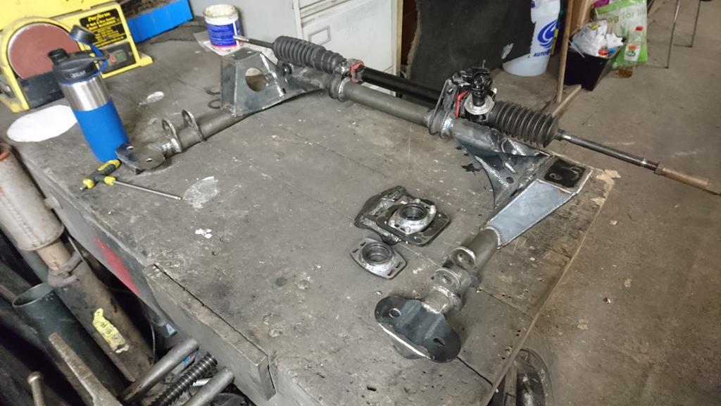 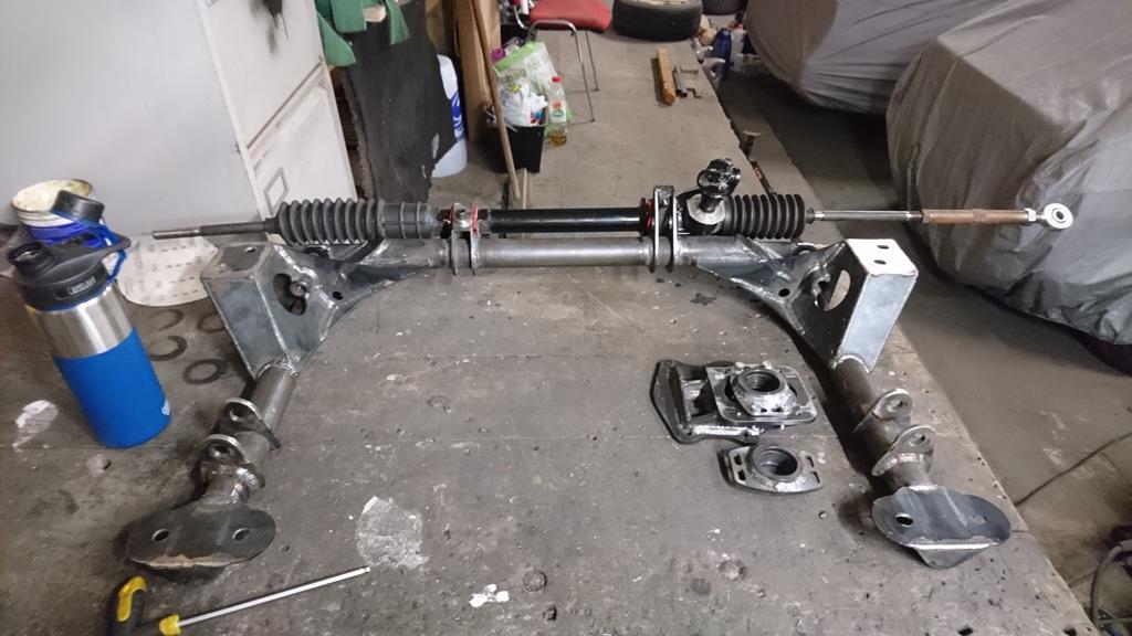 Unfortunately until I modify the engine mounts to raise the engine 20mm the subframe doesn't fit the shell at the same time as either the sump or steering rack, but I knew that would be the case. (The joy of wanting a low car that also goes round corner like one at a sensible ride height!) The pivot points are at the 650mm centres I intended too. I'm really happy with that end result even if the route there was a bit winding and doubled back at times. You may spot some more time travel in those photos where a few bits of top mount have appeared. I'll get into that in my next post as it's late!
|
| |
Last Edit: Nov 11, 2018 0:20:28 GMT by RobinJI
|
|
|
|


 I've still not even started the Scirocco and I've spent all the time in-between trundling around in a gutless diesel daily driver. If I'd been able to keep up the momentum that I had when I started this, it would be done by now but sadly I've been finding it increasingly difficult to prioritise spending much time on it, both in terms of motivation and practicality.


 ) but other than the welding it's mostly there.
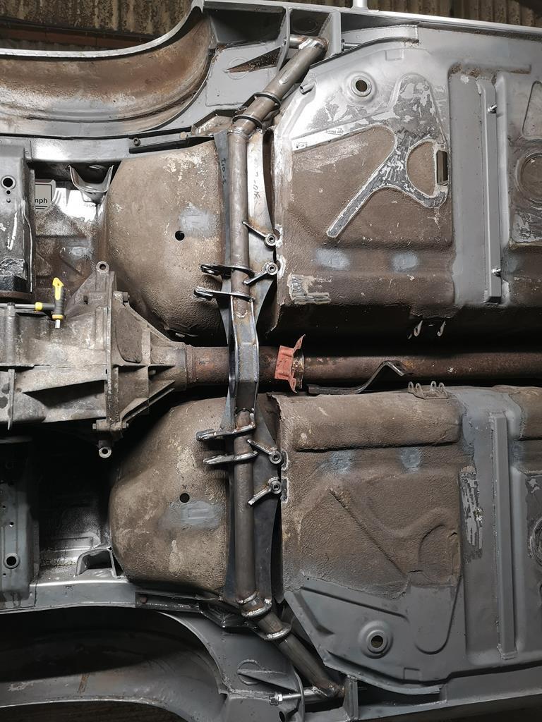


 I still need to turn down and weld in the crush-tubes as I've been meaning to check something on the model and only remembered to when I got home earlier. I'd been having doubts about my choice of 'neutral' camber. By which I mean the camber setting when the adjustment's set centrally. I'd drawn everything around this being 1.5deg but the more I thought about it, the more it felt like this might be a bit conservative and result in only one direction of the adjustment being useful. The easiest fix for this would be to turn down one of the crush tubes so that the hole's eccentric in it. Having checked the model again I've got plenty of adjustment for more negative camber even as it is, so there's no need to mess with things and next time I'm at the unit I can turn down the crush tubes and weld them in.
 . As for tungsten grinding I'd been getting the direction of the grind right but I hadn't realised I was supposed to leave a slight flat at the end of it, I'll try that next time, thanks!