RobinJI
Posted a lot
 "Driven by the irony that only being shackled to the road could ever I be free"
Posts: 2,995
|
|
|
|
That's clever to keep that extra tabs on there, just grind them off after welding. I don't know with laser cutting, but with plasma cutting the cutting edge is hardened by the heat of the plasma arc, tends to weld horribly. I always grind them clean before welding. Knotted wire wheel does the trick also. Great progress Thanks, I'm really happy with how they worked. Also thanks for the tip with the hardening, you do indeed get a hardened edge from laser-cutting but it's usually clean and in my day job I'd been getting stuff laser-cut for other people to weld regularly for the last 5 years, so I wasn't expecting welding to be an issue! It has tended to be rare for us to TIG mild steel though, so I did have a go at cleaning a few of the edges back so the hardened area was removed. As a little slightly-related note, the hardened edges make it an absolute pig if you get holes cut to the tap-drill size then try and tap them! As a result the top mounts that will be tapped to M6 have been cut at 4mm, to be opened out to 5mm in the pillar drill then tapped to M6. (4mm because most suppliers can't cut holes smaller than 2/3rds the plate thickness due to heat-buildup.) wow at the kit parts, it looks incredible. also wow at those top mounts, brunel spec, shall i just delete my previous reply  Thanks! It's really cool seeing it all in the metal having been sketching away of the computer for a fair few evenings in front of the TV. They are probably pretty damn over-built. Still, better safe than sorry and while I'm a big fan of keeping weight low, I also don't plan on treating this car gently when it's done! (Or it's probably more accurate to say I don't want to have to treat it carefully, I don't intend to abuse it.) I absolutely love following this thread and this has just taken it to a new level. I must admit I did have the same concerns as darrenh about whether you could move the top mount safely but they look really stout. Will this not transmit more of a twisting force on the original mounting in the body though? Although I suppose they will have been designed to withstand pushing and pulling anyway and a twist is just half of each. Just trying to understand  . Can't wait to see these come together. I think the offset topmount will work great, the 924 chassis has very well supported shocktowers witch are almost integrated in the firewall, so i woudn't worry avout it. Great build so far Yeah, the strength of the shells top mount is absolutely something to consider! I probably wouldn't be happy running these on my Scirocco without some reinforcement to the shell, however as Peter says the top mounts on 924s are very sturdy! They're double skinned with the outer skin forming a box section surrounding the top mount, then there's a large box-section area that runs rearwards from them to the structure of the bulkhead and a pair of box-sections running down to the top of the chassis leg. There's also the cage-leg running forwards to add some strength and I'll be adding a fairly substantial strut-brace once I know where things will sit in the engine bay. Essentially, I'm happy the shell can take it. This shot gives a fairly good idea of the towers: 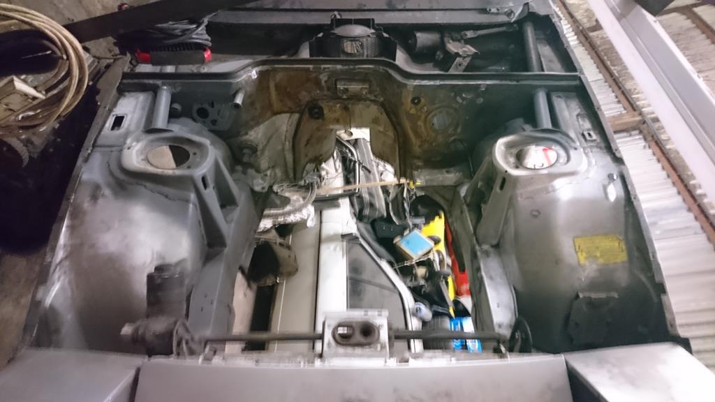 Going back to re read everything <<<< Bookmarked. Thanks, I think! (I guess it depends what you find when re-reading!) I haven't got fully caught up, I was following this though to about march and then forgot to come back. Its been sunny outside ect, so Ive just started reading the last 4 or so pages. Great work, ive got a 944 and ive always like the idea of keeping that for the road and tracking a 924. Quiet frankly youre not helping Thanks! I was thinking the other day that it would be pretty cool to have a more road-friendly 924/944 as they definitely suit being a genuinely usable classic sports car. Sadly I just don't have space in my life for yet another car and I intend my Scirocco to fill the role of road-friendly usable retro. To catch things up to today: I had another brief go at the TIG welding last Thursday at the end of work, I REALLY cleaned everything up, removed the hardened edge from an area, emery-clothed it like mad then drenched it in acetone! It was bloody clean! Sooo... the result, the exact same thing which resulted me promptly going home in a strop. Then, during the day on Friday I glanced across at the welder and had an 'Am I really that thick' moment. I think it's safe to say why the welds were getting contaminated!  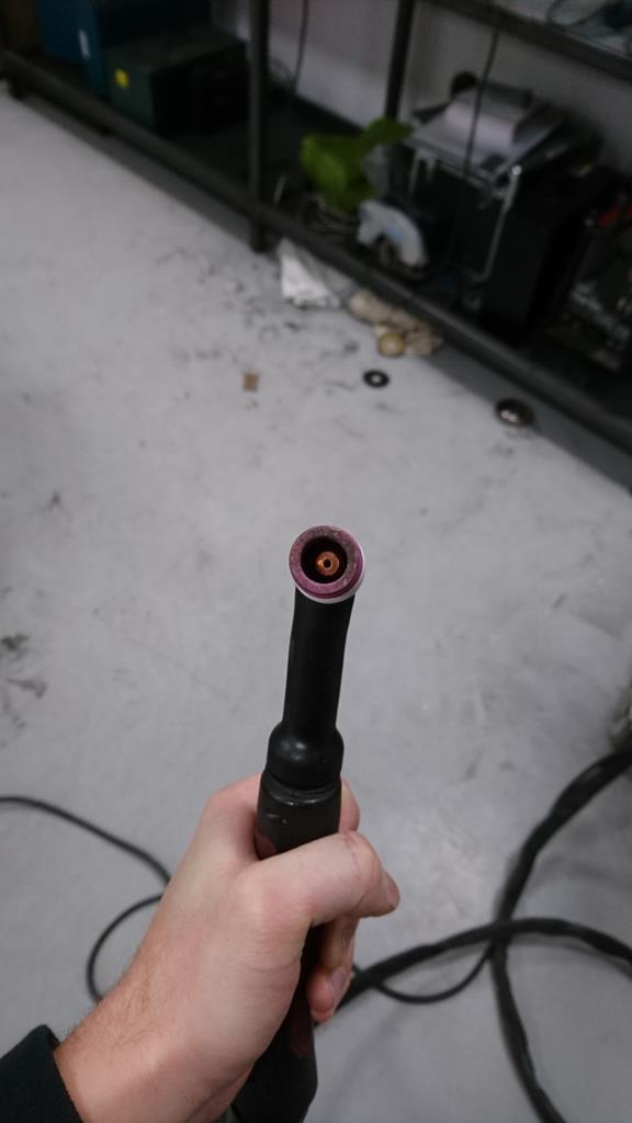  Yeah, the gas probably isn't going to do a great job of shielding anything when it's being fired off to the right! It must have got a knock since we'd last used it for work but luckily nothing was even bent, it just needed slackening off the re-tightening carefully! With that done I tried a little bit and it came out quite well. Looking at the arm I'd 'tacked' together, cutting it back apart without taking an awkward amount of material out of it didn't seem like a fun task. With that in mind and being well aware that I'm no expert TIG welder I decided to write this arm off to experience and finish welding it up as some much-needed practice. I won't be using it on the car as I'll never be able to get rid of the porosity in the initial tacks and I didn't expect to be over the moon with it visually either. Much as expected the arm didn't come out amazingly but I was happy that by the end of it I was ready to tackle a 'real' one. If I can get all the next arm looking like these last bits I'll be over the moon! Note the horrible nasty-ness further down where the gas wasn't doing it's thing: 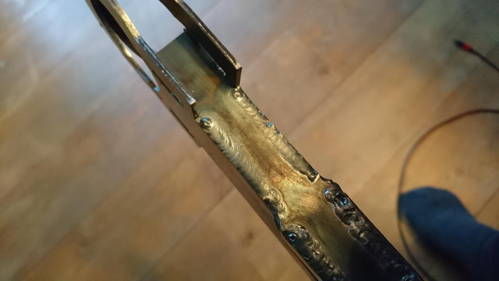 In reality I expect bits of it to be a little messier but even the bits that didn't look quite so good on the practice arm had good penetration and I'd be happy were nice and structural. (I'm not a fan of saying messy welds are fine and structural, generally if it's right it will naturally look good, but in this case I'm being quite fussy, they had good penetration and a smooth surface.) I'll try and remember to get some photos of the messier bits. I also did some work on the front subframe over the weekend but I've been staring at a laptop long-enough for now (is anyone else having trouble with photo uploading? Mine seems to sometimes not actually give me the link when it's done uploading?). I'll catch up with Sundays work later! |
| |
|
|
|
|
RobinJI
Posted a lot
"Driven by the irony that only being shackled to the road could ever I be free"
Posts: 2,995
|
|
Oct 31, 2018 21:15:19 GMT
|
Lasers are awesome: 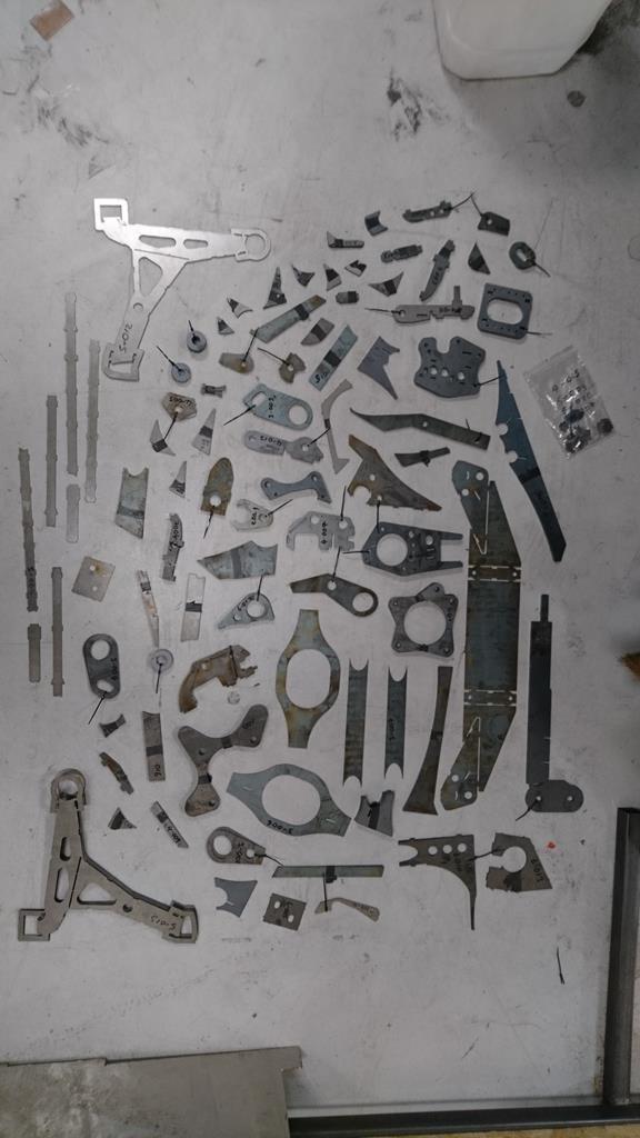 I haven't got a huge amount further than just checking everything was there and loosely wedging things together to take a look at how they might come out. I did start tacking together one of the front wishbones but I was really struggling with contamination in the welds. I haven't done much mild steel TIG before and I think with the state it's come from the laser cutters it'll all need skimming over with a flap disk anywhere I'll be tig welding. I tried emery cloth, isopropyl and the a good wire brush but it evidently wasn't enough. Hopefully I can get the tacks back apart without doing too much damage. You can see the internal structure of the arms here: 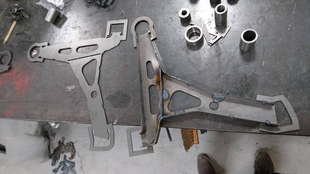 You may notice the ends having some extra bits, which is because thinking ahead I got them cut with some extra metal to surround the turned parts in an attempt to make the arms self jigging. It seems to work quite well. You can see how they locate everything here: 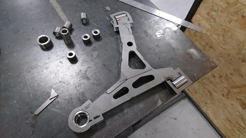 Including the angle one of the rose joints needs to sit at to clear the chassis leg: 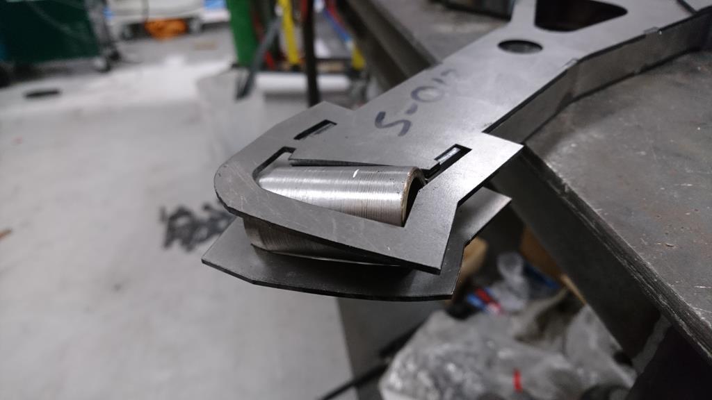 I loosely placed the parts of the front uprights together but no photos as it took two hands to hold everything in place. I can't make a start on them as I completely forgot that the outside diameter of the crush tubes needed turning down and left them at the 25mm of the bar stock I started with. I placed the top mounts loosely together too, no real reason it's just satisfying making stuff look like it might work! 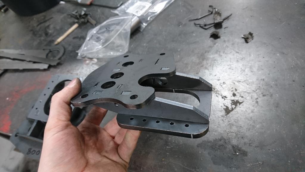 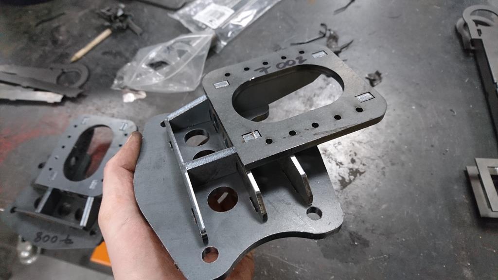 Hopefully there will be some more progress soon. |
| |
Last Edit: Oct 31, 2018 21:19:56 GMT by RobinJI
|
|
RobinJI
Posted a lot
"Driven by the irony that only being shackled to the road could ever I be free"
Posts: 2,995
|
|
Oct 29, 2018 20:04:18 GMT
|
Thanks peter! They've made some seriously cool cars! I wasn't aware of the company before but they seem awesome. Impressive weights for their built to order stuff! I've been enjoying keeping an eye on your shed built racecar thread, that things going to be very cool. i was already thinking just move the turrets, but that doesnt fit with no shell mods ethos. the cantilever top mounts, is that a thing, will it be ok ? Yep. Plus it would be a pain to do on a 924, the turret's pretty well integrated into the front end's structure. As for the top mounts strength, some quick FEA suggests they'll be absolutely fine. There's very little cantilever to them really, the load's only just going in behind the rear two bolts and they're made from 6mm steel with quite a bit of structural bracing going on. Worst case I could sink some captive nuts into the inner wing and brace up from the back of the mount but I honestly don't think it'll be necessary. Cantilevered brackets are often used to mount coilovers on double wishbone setups sticking out the side of chassis members. Being a strut wouldn't increase the vertical loading, only the lateral which the cantilever wouldn't really effect. |
| |
|
|
RobinJI
Posted a lot
"Driven by the irony that only being shackled to the road could ever I be free"
Posts: 2,995
|
|
Oct 28, 2018 20:10:52 GMT
|
Thanks Adam! And that's the last of them: 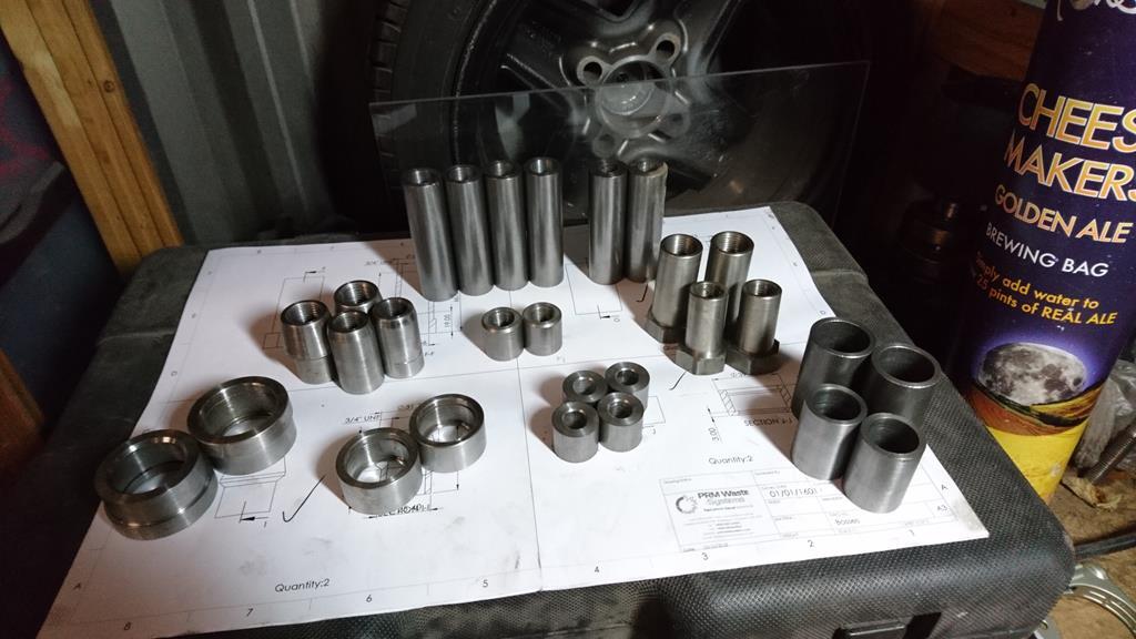 That's all the turned parts ready for the suspension. The idea will be to collect the laser-cut parts Tuesday after work, then in the evenings the rest of the week I'll try and get the parts I intend to TIG weld done at work then bring everything back to the unit to build the subframes using the shell its self as a jig. |
| |
Last Edit: Oct 28, 2018 21:18:33 GMT by RobinJI
|
|
RobinJI
Posted a lot
"Driven by the irony that only being shackled to the road could ever I be free"
Posts: 2,995
|
|
Oct 27, 2018 22:22:38 GMT
|
Thanks Woofwoof. The skills are very much being made up as I go though! I studied motorsport at uni, and until this year I'd spent 4 years as a design engineer for a fabrication company without getting my hands dirty, so I've been loving treating this car as a way to put theory into practice! Thanks Darren, we'll have to see how the real life counterparts turn out, don't speak too soon! I've run a few more renders of the changes since the ones I showed in my earlier post. The back end's changes are easy, I just snugged the tube running through the subframe up a little higher to get it closer to where the loads will be entering the subframe: 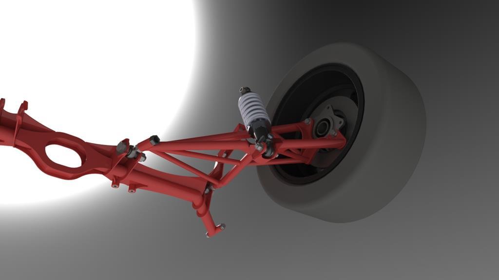 The changes to the front end were a result of doing a bit more measuring then being too stubborn to compromise the geometry. In the earlier design I'd moved the front axle line forwards to increase the caster angle, and it had been moved further forwards by me offsetting the stub-axle from the steering axis. I'd initially thought that there would be enough clearance as I'm running smaller tyres and the 924s arches looked big. Before ordering anything I thought I'd better double check though and quickly measured up a few key dimensions of the inner arches/arch tubs. Boy was I wrong, it wasn't even close to clearing with the small tyres and if in the future I went to larger wheels and a Carrera GT kit (which I can imagine happening in the long-term) I'd have had no hope! The problem is, I'm feeling stubborn about not modifying the shell. I know that seems silly after all the cage work and things, but other than the odd hole for a tube to poke through and the spare wheel well, I really haven't touched the body shell. I want to keep it this way partly just as an arbitrary 'goal' for the build, (it's more fun working within some sort of restrictions, and it stops me getting in too deep; after all, if I go cutting things up to make this set-up work, why not just make space for a proper double wishbone set-up?). The other more explicable/practical reason is to keep things reversible. If I'm not happy with something down the line or I change my intended use of the car, or even if I take it racing and there's restrictive rules, it's nice to know it could be put back to standard running gear easily. I found myself wanting to keep my desired castor angle, but I knew if I moved the wheel back far enough to clear on lock the strut wouldn't be pointing at the hole it's supposed to mount into, and I didn't want to enlarge or move that hole. What to do? 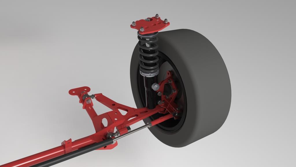 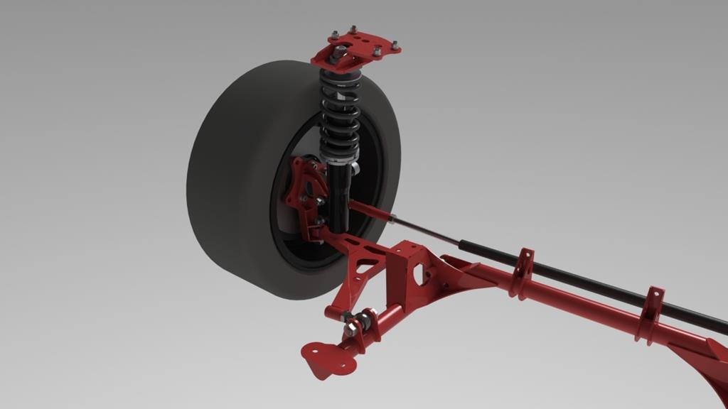 Don't put it through the hole!  As I'm making new uprights and I've moved the wishbone down a fair bit, I was able to move the struts mounting points down low enough to sneak the top of the strut under the inner wing. This lets me used a spaced down and back top-mount to keep the caster angle as I wanted without having to cut anything away. Oh, and don't worry, it looks close but it does clear the wishbone on full droop. As you can see from the images, the wishbone's not been changed but instead it's mounting points have moved rearwards to get the bottom ball-joint centred in the arch-tub again. You may also notice that the strut top is offset outwards quite a bit compared to the factory one (which would be central between the 4 mounting studs you can see). This is to minimise the KPI in order to minimise the positive camber a high KPI introduces when steering. As the struts are 'direct fitment' to a normal 924, they have the camber adjustment with an eccentric bolt. Couple this with the fact I'm making the uprights so can set a fair bit of negative as the 'starting point' and there's no need to use the top mount to gain camber. I also meant to mention, this has all been designed around the ET42 offset Mazda wheels I'll use to start with. I've pushed the track width out a lot, it's what I think is as far as I can in the standard arches with these offset wheels. If I ever go to a Carrera GT kit then hopefully simply using lower offset, but still sensible wheels will fill them nicely and in the mean time it'll hopefully look quite cool just about squeezed into the narrow-body. Oh, one thing I forgot to mention. Anti-roll-bars. Or lack thereof. I've designed this lot with no ARBs simply because I'm not the biggest fan of them. I want the car to be as controlled in squat and dive as I do in roll and it's quite a low slung car which shouldn't roll horrendously anyway. As they do tend to rob a little grip by result of how they work I'm going to start without them, then retro-fit if necessary. If I do make some up for it down the line, then there's plenty of ways of attaching them that don't need me to make allowances at this stage. Essentially, that's a long winded way of saying I'm going to worry about them later! |
| |
Last Edit: Oct 28, 2018 8:37:45 GMT by RobinJI
|
|
RobinJI
Posted a lot
"Driven by the irony that only being shackled to the road could ever I be free"
Posts: 2,995
|
|
Oct 27, 2018 18:14:33 GMT
|
Well, after a little break I'm starting to make some more progress with the Porsche and happily its the shiny new parts kind. Well, sometimes shiny. America was awesome. The truck we rented was great in a tacky, luxurious barge kind of way, it soaked up the 2500 miles we cruised around for on our way from Boston to Miami and averaged 20mpg (US gallons), which I thought was impressive for a 2750kg, 385bhp petrol truck: 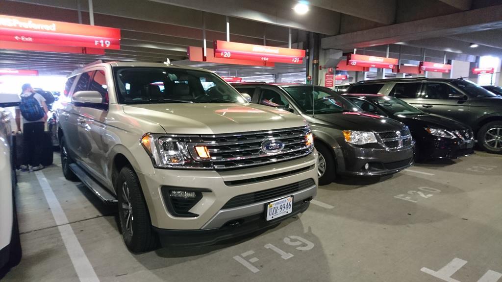 I'll leave a few shots of the sights along the way then get back to old car stuff: Boston, a cool city with a good character to it: 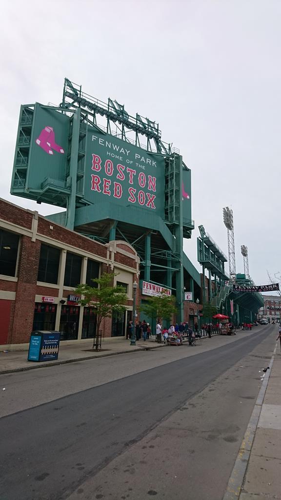 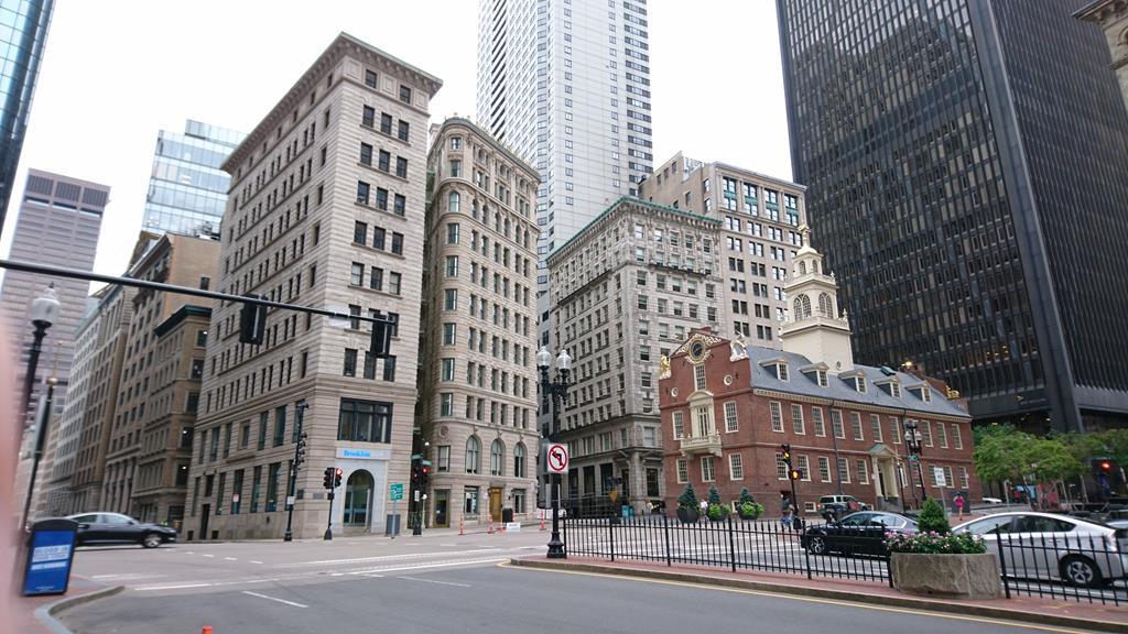 Atlantic City, amusing but pretty tacky and trashy: 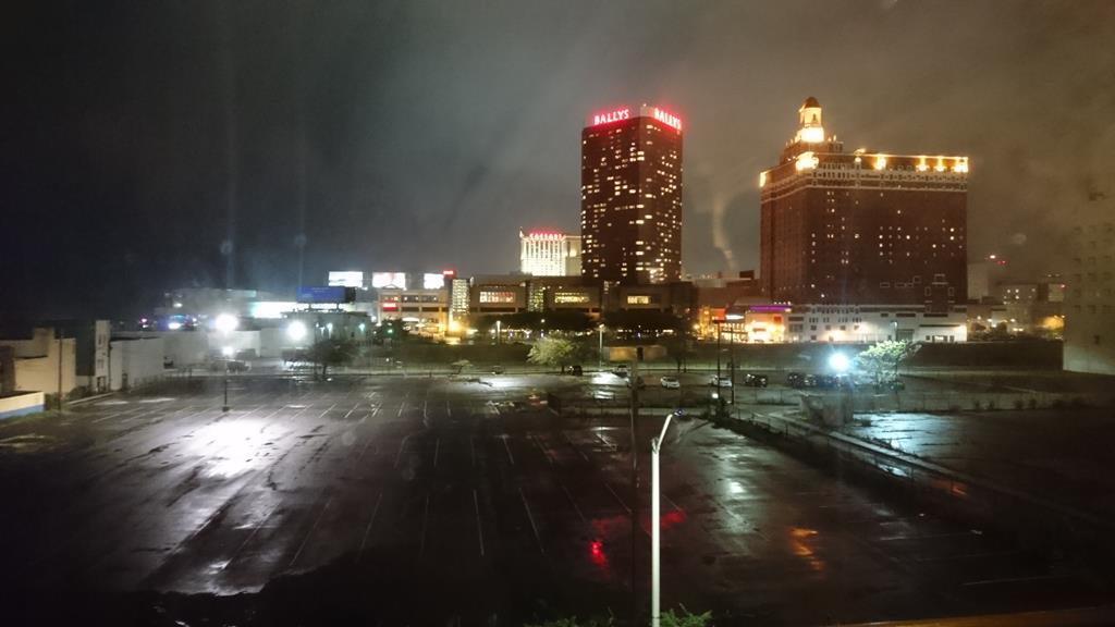 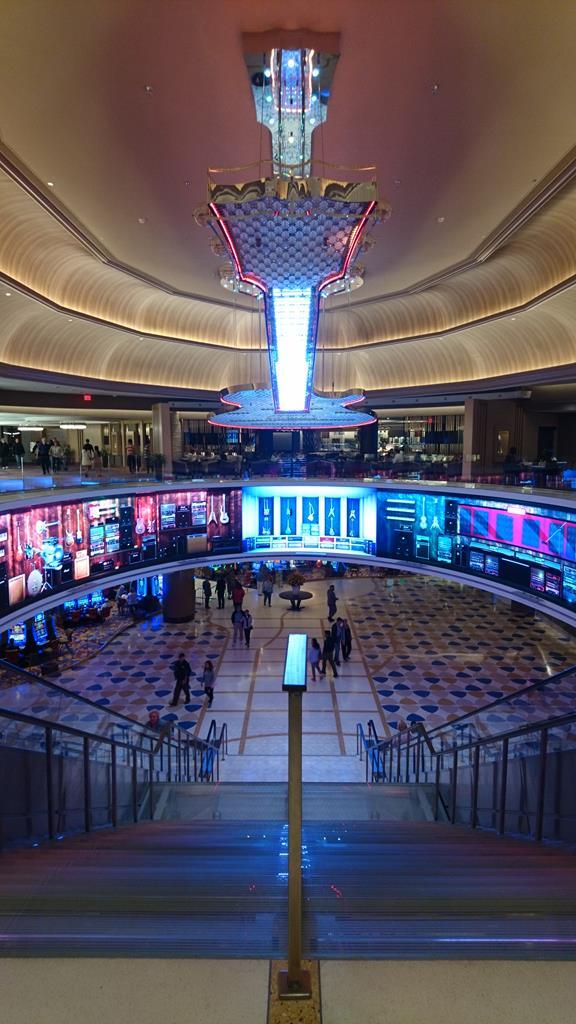 Philadelphia, not much stood out about it to be honest, bloody good greasy sandwiches though!: 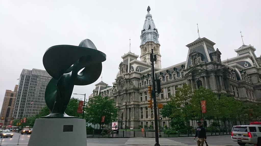 Washington DC, cool to see the sights:  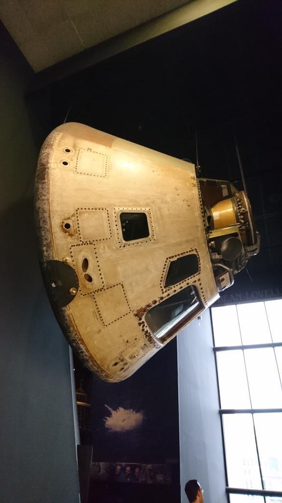 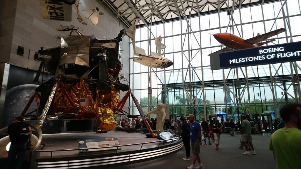 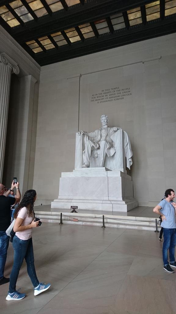  Kennedy Space Centre, seriously cool, I could have spent days there: 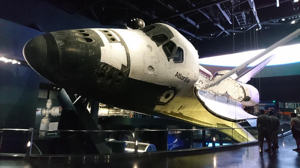 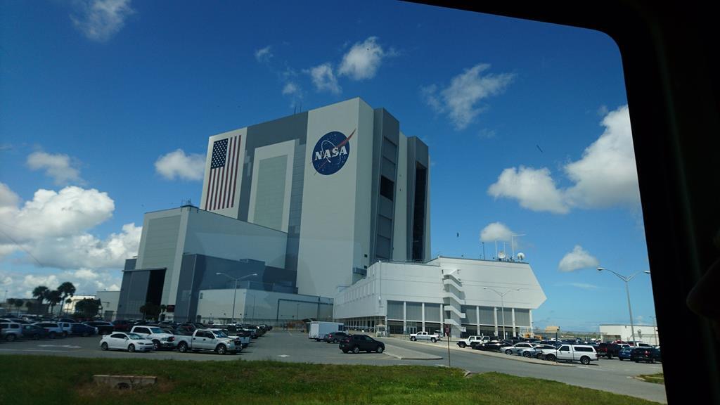 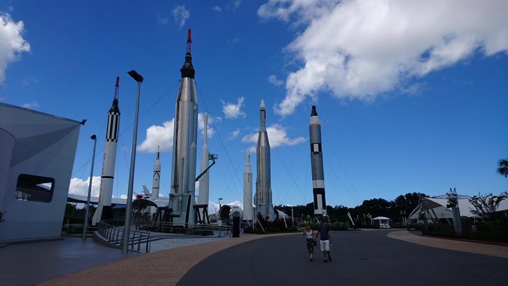 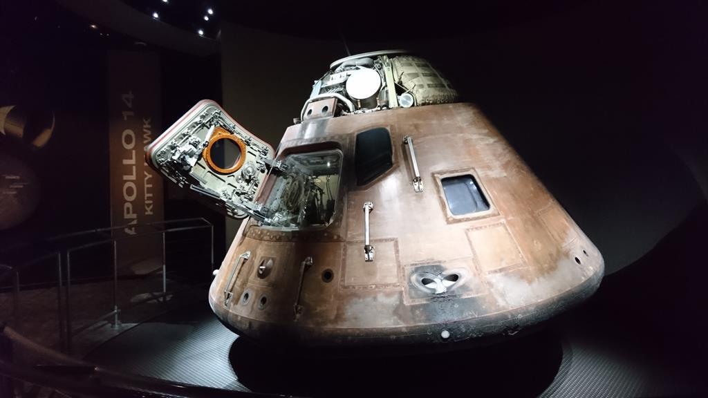 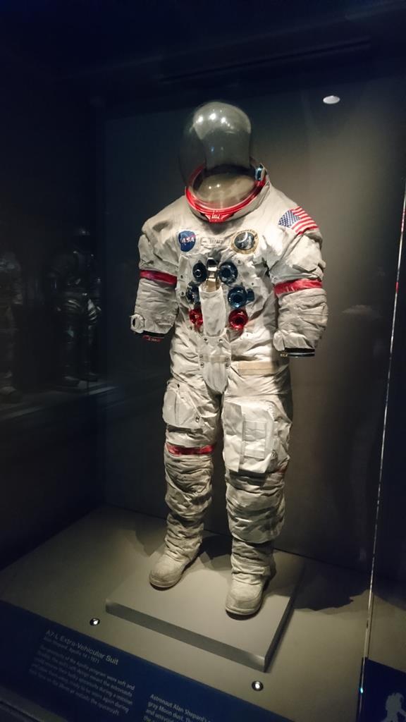 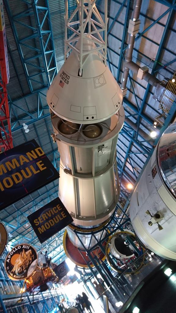 Roller Coasters in Tampa, great fun: 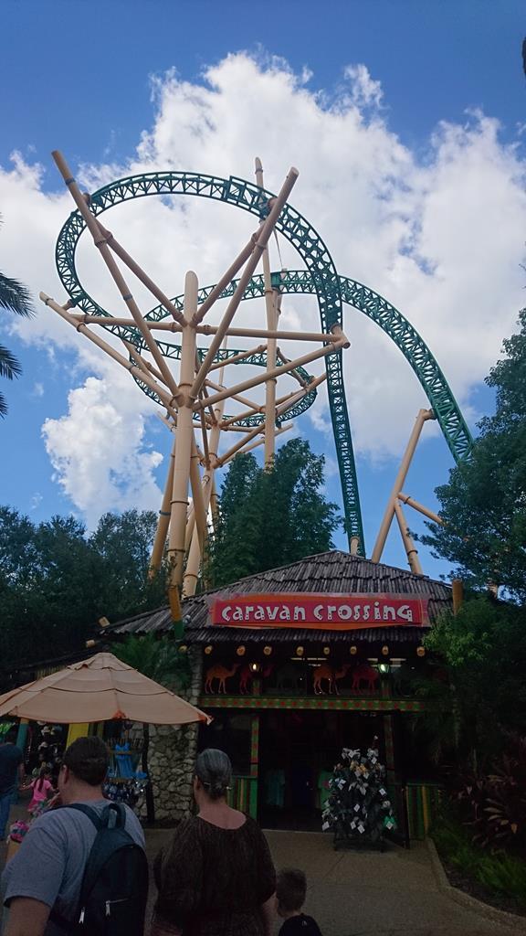 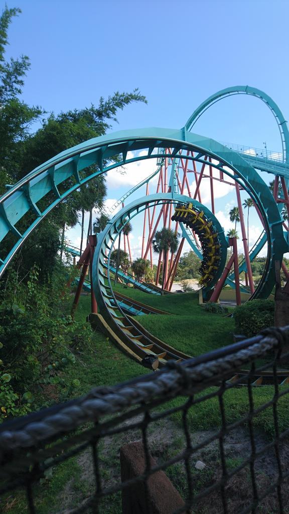 Gators in the Everglades: 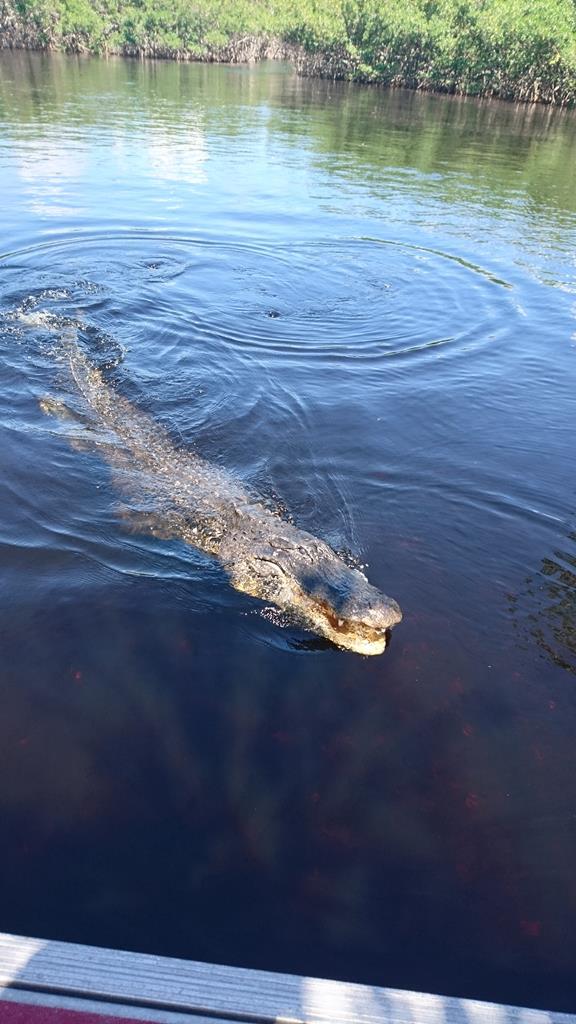 The view from our Air B&B in Miami: 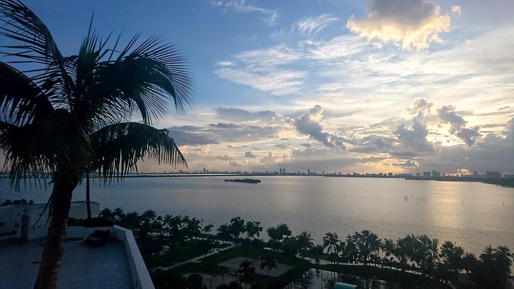 Florida Keys, so much bridge!: 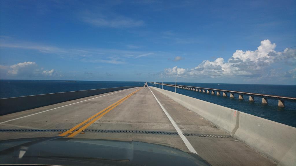 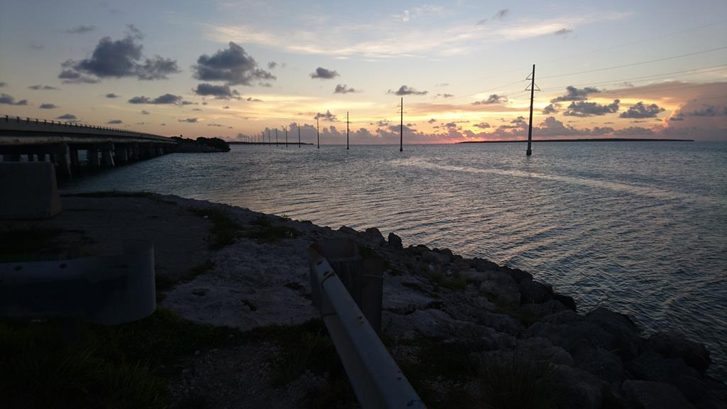 And finally, New York:  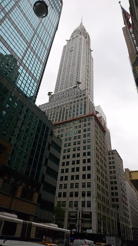  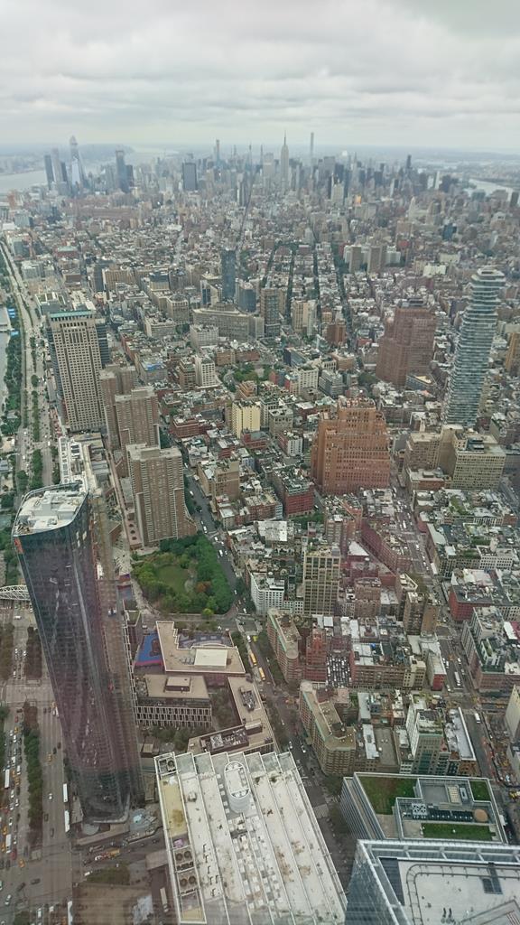 Right, back to old cars: As I mentioned a couple of posts ago, excitingly I'm now essentially done with the shell until I've assembled all the mechanical parts (as I intend to pull it back apart to paint stuff after I know it all fits right.) I've been designing some new suspension over the last 6 months or so and I finally got all the measurements I needed, allowing me to finalise the designs and get all the parts ordered This is the plan (Well, kind of, the front subframe and top mount's changed a touch but I haven't been bothered to re-render it!): 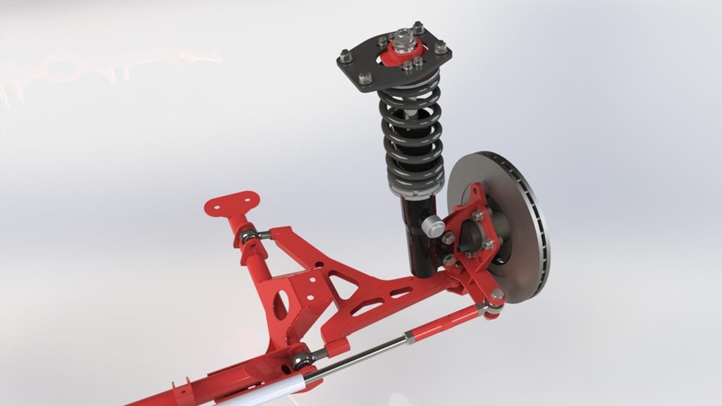 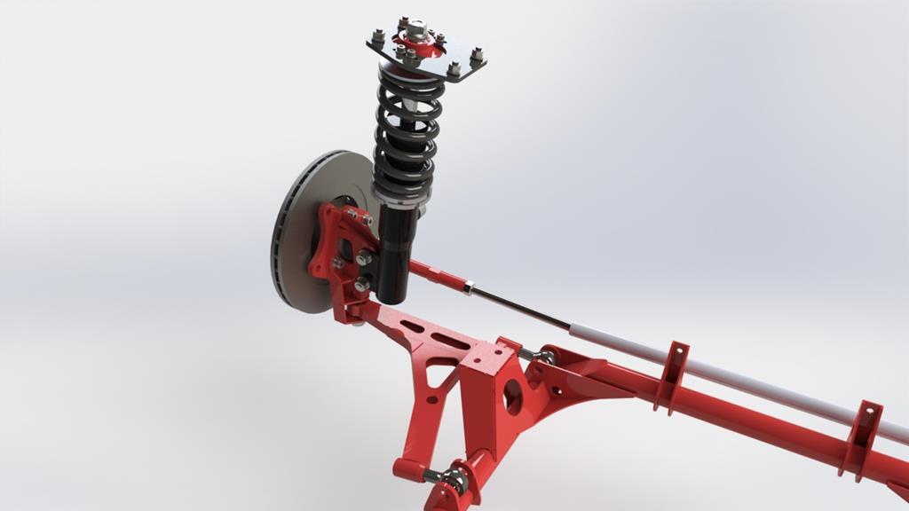 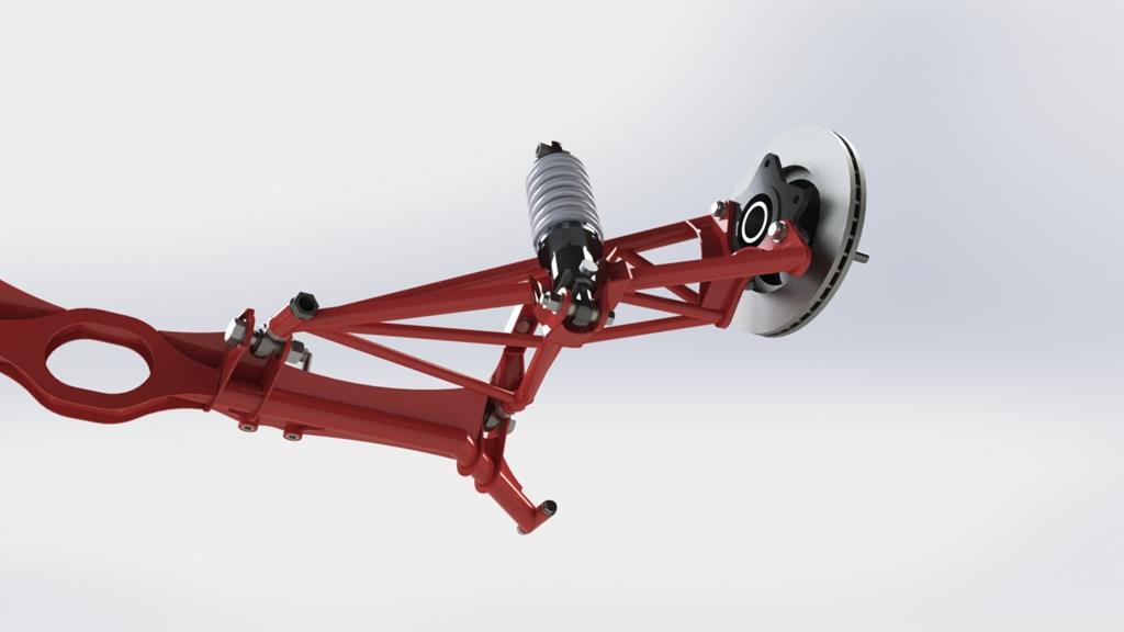 And what I've messily modeled to give me the info I need to build it around: 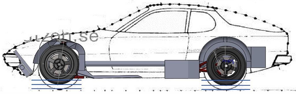 (The blue lines at the bottom of the wheels are showing ride height and the extremes of the suspension travel. There's roughly 70mm compression travel and 50mm extension front and rear with a ride height of 80mm front, 90mm rear under the sills.) Up front there's a tubular subframe that braces from the original wishbones rear mounting points to the front crossmember's mounts, rose-jointed monocoque front arms, fabricated plate front uprights and adjustable spherical-bearing style strut-top mounts. This lot's built with 8° Castor and 17.7° of KPI with the axle centre 20mm farward of the steering axis. Hopefully this will give better geometry than the original very low castor set-up while keeping a sensible weight to the steering. It's all fairly adjustable though so if it's not right I can experiment. The wishbones mounting points and the steering rack have all been moved up as much as possible, and the lower balljoint and steering arm on the upright are moved down as far as wheel clearance allows, all to give decent camber gain and roll centre characteristics at a pretty damn low ride-height. The uprights are designed around using Yaris rear stub axle/wheel bearing assemblies and mk2/3 Golf brake set-ups. The whole lot uses a mk2 Escort 2.4 turn 'heavy duty rally' quick-rack. Out back I've kept things semi-trailing arm but I'll be ditching the torsion bars and making new tubular, rose-jointed arms with bearings from a mk4 golf. These will be used with mk4 golf hubs re-drilled to 4x100, audi S3 rear brake calipers and a corrola E10, 255x22 front disc brake. The 'subframe' has the mounting points moved up as much as space will allow and I've built an inclination into the pivot, with the inner rose-joint slightly lower than the outer. This corrects the common semi-trailing arm issue of gaining toe out under braking once lowered but the inner mounting point needs to be moved accordingly if I ever raise/lower the car and want to keep this effect, so I've made that point adjustable vertically. There's a bolted connection between the wheel bearing and the arm which can be shimmed to adjust camber and toe. I've spaced the bolts there out so that they're adjustable independently from each other, and so that a 1mm shim is equivalent to 1° of adjustment. Toe can be more finely adjusted by the rose-joints on the arm too. The subframe's got a big hole in the middle for the exhaust to pass through and it'll be bolted solidly to the shell at 4 of the 6 original beam's mounting points as well as the fixing points where there was a tunnel-brace. I'll have to make some 'hybrid' shafts out of the porsche ones and some mk4 golf ones, but as they're both tubular I should be able to keep them strong fairly easily. Time to get making all this! During the last week my eBay's taken a hammering to provided me with some 28x2, 18x2, 28x3.25 and 31x3.25 CDS pipe, a 1m bar of Ø25mm EN8, 600mm of 1 1/8" 303 Stainless hex bar, a drill bit and a couple of taps, which gives me everything I need that isn't a piece of flat plate. Everything flat's getting attacked with lasers until it's the right shape and should be ready to collect on Tuesday I'm a bit excited for that! In the mean time I've been getting to work on what I can, which is essentially twiddling knobs on a small Chinese lathe until I've ended up with this lot: 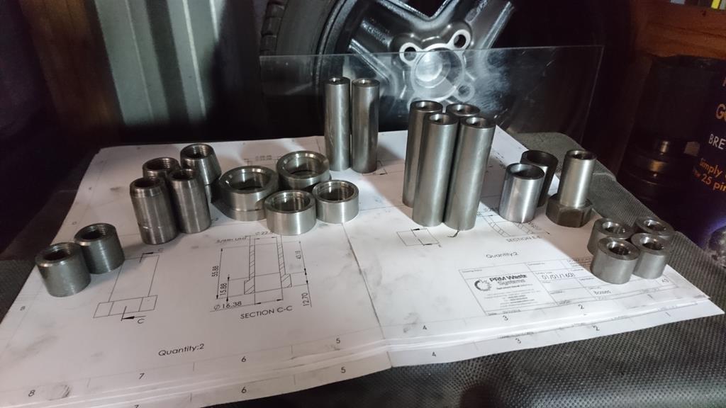 Left to right, these parts are: - Ø25mm O.D. 5/8th UNF threaded bosses: these act as captive nuts in the front subframe for the wishbones farward bolt. - Threaded inserts: 2 with 5/8" UNF and straight sides, 2 with 3/4" UNF and shaped sides. These were bought from McGill Motorsport then modified. The 5/8" ones are for the rear rose joint on the front wishbones, the 3/4" ones are for the inner rose joint on the rear arms. - Bearing holders: 2 for 5/8" spherical bearings (com10t) which will be the 'lower balljoints' welded into the front wishbones, and 2 for 3/4" spherical bearings (com12t) which I've turned a step into. Welded to a laser-cut plate these will form the top-mounts. These were from McGill too. - Ø25 O.D. Ø12.5 I.D. 83mm long bosses, these will form the ends of the rear subframe, bolting into the shell where the rear beams end bushes used to. - Counter-bored Ø25 O.D. bosses, these are counter-bored both ends and will be the other mountings for the rear subframe, bolting to some fixing points either side of the transmission tunnel under the rear bench. They're drilled for an M10 bolt then one end's counterbored as the fixing points have a little spigot that requires it to get a nice mounting, the other end's just for cool-points to hide the head of a cap-head bolt. - Sleeves: These are just some bits of Ø28x3.25 that I faced the ends of in the lathe and they'll get welded into the front arms where the front rose-joint threads in. - Hex ended, internally threaded boss: This is a stainless boss that will work with the sleeves of CDS next to it, this is what the rose joint will screw into, which allows it to be adjusted infinitely finely and in-situ, instead of only in half-turns when unbolted like the other rose-joints inserts on the left. - Ø25 O.D. Ø12.5 I.D. stubs: These will be welded into the front uprights where the strut bolts to it to act as crush tubes and set the 20mm width to match the struts. Right, I'm off out to watch a friends band and try and get the sight of a tiny lathe un-burned out of my eyes. I've got 3 more parts to make, and the laser-cut bits to pick-up on Tuesday and I'll be able to start welding some suspension together. |
| |
Last Edit: Oct 29, 2018 8:30:18 GMT by RobinJI
|
|
RobinJI
Posted a lot
"Driven by the irony that only being shackled to the road could ever I be free"
Posts: 2,995
|
|
Oct 11, 2018 13:49:58 GMT
|
I believe they recently introduced a very draconian ruling of it being the speed limit, no leeway, go over by any amount and it's a penalty. I could be wrong but that's what I understood. For some reason I thought that was only in a certain region, Wales or Scotland I think? I know it certainly used to be regional. When I did a course in Somerset 10 years ago it was 10% +2, so 34 you were ok, 35-39 you got an awareness course and 40+ you got a ticket. Loving the Pop by the way, the IVA side of things got me starting to read this thread, but I've kept following it for ages just because of how cool the car is and the quality of work. Keep it up! |
| |
|
|
RobinJI
Posted a lot
"Driven by the irony that only being shackled to the road could ever I be free"
Posts: 2,995
|
|
Sept 2, 2018 21:52:48 GMT
|
Haha. That crevice tool did get used to clean it out a fair bit! Shockingly, I've managed to work on the car 2 weekends in a row, so I was clearly lying through my teeth last weekend when I said I wouldn't be touching it for a while! Turns out I'm quicker at preparing for a holiday than I'd realised and I found myself at a loose end today. I popped out and measured the fore/aft position of a front turret relative to the underside of the car. I've kept forgetting to measure this and it was the last measurement I needed from the shell for the front suspension design. The other critical piece I've been missing is a set of mk2 golf brakes. As mentioned I'm converting the 924 to 4x100 stud pattern and remaking the front uprights, giving me free reign of brakes as I can put the mounts wherever I want. I considered a few options but in the end decided to go with mk2 golf 16v/mk3 golf/b3 passat etc fitment. This let's me use relatively inexpencive 'g60' 280mm brakes up front for now, and if/when my confidence on track grows enough that they become a weak link, I'll have a good choice of aftermarket upgrades available off the shelf. It dawned on me that I'm actually going to be at a stage to at least dry build the suspension soon, so a couple of days ago I asked around some friends where the best place to find a set of 'g60' brakes was and it turned out one friend had a set of carriers spare from his old mk2! They should be on their way to me soon. The callipers are apparently shared with the 256mm brakes, so if you have the 280mm carriers then callipers are easy to find. When they arrive I can measure them up and I'll have everything I need to place an order for the materials and laser cut parts of the suspension! Which I'm seriously excited about as I get to make shiny new things as a break from fixing rust old ones! Anyway... Once I'd taken that measurement I decided the bulkhead was looking a bit colander like with a lot of surplus holes in it from things that won't be there any more. In this shot you can see I'd already welded up the hole the master cylinder used to get pushed through but there's still a bunch of holes around it: 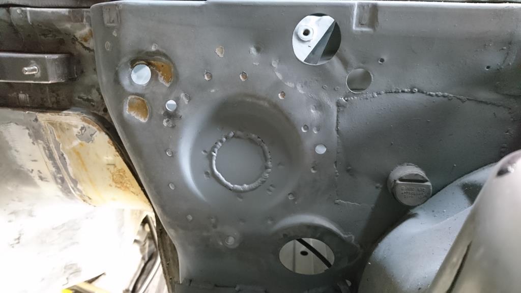 Cut out some of these: 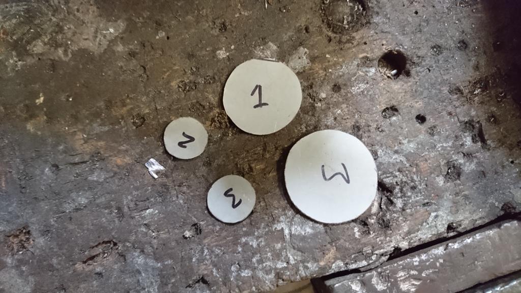 Buzz buzz: 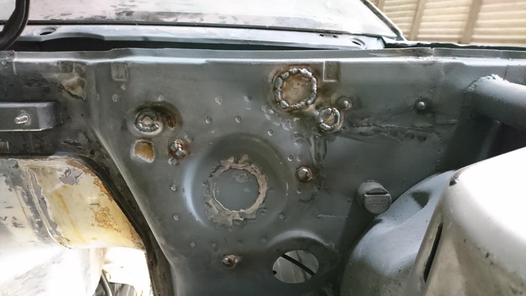 Some sparks later:  And some silver zinc paint. I've run out of zinc primer and can't leave this bare as it'll probably be at least 3 weeks before I get a chance to head out with some more, so I've painted it with zinc paint for now. I don't thing this stuffs adhesion as good as the zinc primer I've been using, so annoyingly I'll be buzzing this back off before priming it properly at some point. The not very nicely done patch over to the right of the shot is also part of the battery tray repair that I regrettably rushed to get the car back on the road before realising how bad the rest of the car was. It's not as bad as it looks and should be hidden by highbuild, or worst case a very light skim of filler: 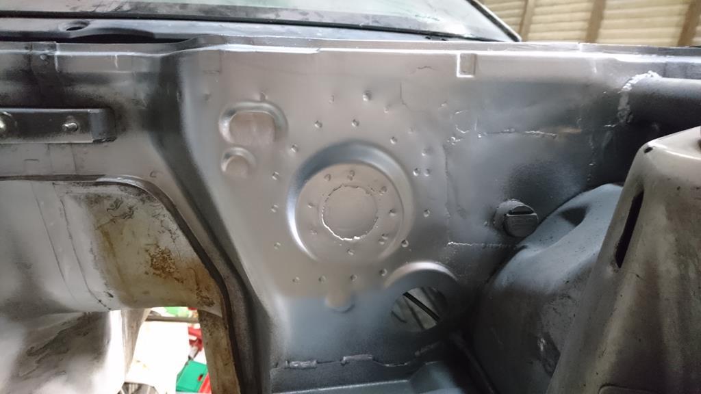 All I've left is the main wiring loom hole and the bonnet release cable's hole. The latter might well also get welded up at a later date. My 'to do before my holiday' list at work is big enough that I can't see myself fitting in any evenings on the car this week, so as I'm flying out to Boston on Friday this probably really is the last instalment for a few weeks! |
| |
Last Edit: Sept 2, 2018 22:05:54 GMT by RobinJI
|
|
RobinJI
Posted a lot
"Driven by the irony that only being shackled to the road could ever I be free"
Posts: 2,995
|
|
Aug 31, 2018 20:23:19 GMT
|
|
Haha, I'm with you on that, there's definitely some satisfaction to it. Weld spatter and swarf both make a pleasing sound as they ping and bounce their way up Henrys nose!
I'm guessing that thought was triggered by the spatter all over that shock mount? It did get a bit spattery as it was a nightmare of a corner to get in at and clean all the underseal and seam sealer off. Even after attacking it with a knot wheel on a grinder, a selection of wire wheels on the drill and my little finger sander there was still a little gunk in places I'd rather it hadn't been. Still, it's certainly stuck on there bloody well and the shock mounts weren't exactly weedy to start with, the bolt goes through a beefy crush tube right through the chassis rail, through the shock then through this bracket to place it in double sheer.
|
| |
Last Edit: Aug 31, 2018 22:22:05 GMT by RobinJI
|
|
RobinJI
Posted a lot
"Driven by the irony that only being shackled to the road could ever I be free"
Posts: 2,995
|
|
Aug 30, 2018 22:15:59 GMT
|
Managed to pop out again this evening. One braced up off-side shock mount to go with the near-side one I did at the weekend: 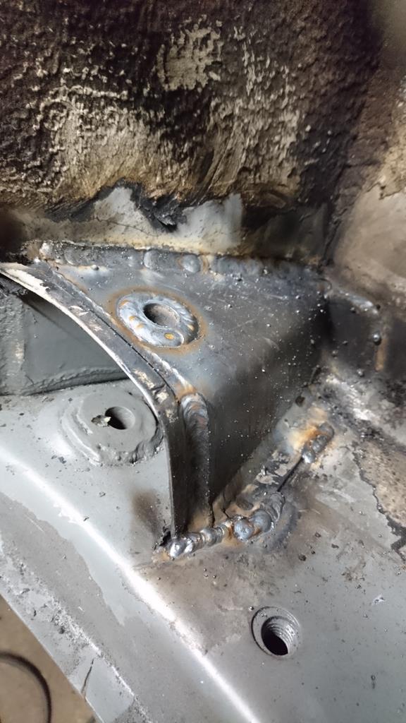 As a random little side note, I noticed that at the angle the car was rotated to, it was clear to see the way that the cage wraps around the cockpit, with the outward 'bulge' of the doorbars visible as well as their alignment with the front strut bracing and the bracing from the main hoop to the rear legs. Hopefully this will provide a nice force path around the cabin should the worst happen. Probably not bad for chassis stiffness too! 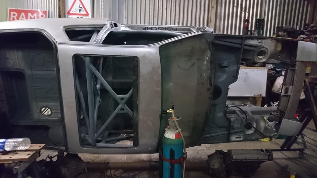 |
| |
|
|
|
|
RobinJI
Posted a lot
"Driven by the irony that only being shackled to the road could ever I be free"
Posts: 2,995
|
|
Aug 27, 2018 21:37:20 GMT
|
Cool, thanks for the recommendation, I'll have to see how close to the coast we stick. West coast is definitely on my list of places to visit! I actually managed to get out the last two days and do a half decent stint on the car! Job number one, clean up the scuttle area. Before (you can see the patched up battery tray which was the first bit of welding I did on this before I started this thread, it was a bit more of a rush job as it was before I'd given up on getting the car straight back on the road: 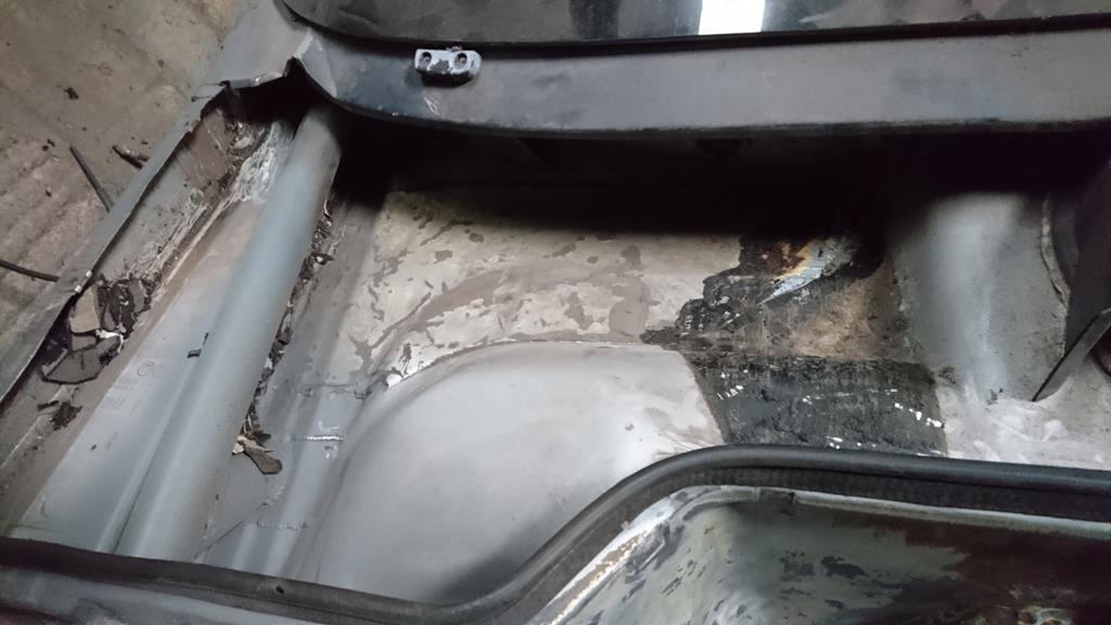 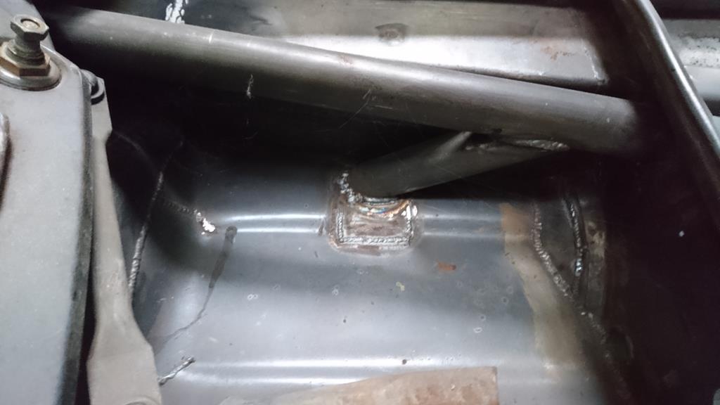 After: 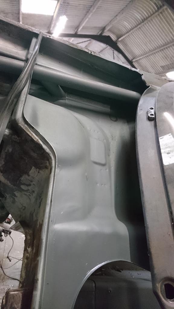 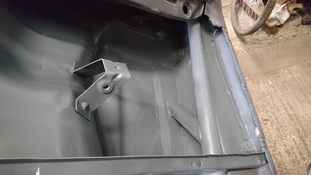 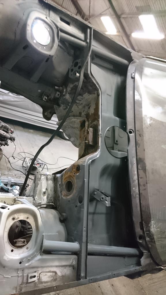 I'd trimmed a bit much out of the inner wing's box section to make way for the cage. I thought it would work well to patch this in with a bit of a spreader plate rather than just a flush fitted section, a decisions made in no way by how much easier it would be to do... honestly... Anyway, although I didn't get any photos that show it, there's also a plate closing the vertical face into the bottom of this one: Before:  After:  I also cleaned up some surface rust on the passenger side engine mount and stitch welded it. I'll be running quite firm polyurethane mounts, so I thought this might be a good idea. Although that said, like a lot of stuff on this shell Porsche's design seems spot on and I'm sure it would have been fine. I really am impressed by the way they put these shells together; everywhere I'd usually want to improve on the thing's already designed in a way where there's no real improvement to be had, it's almost spoiling my fun! I though I may as well stitch this while I was there though, no harm in belt and braces. Not the neatest welds sadly as it was impossible to get all the seam sealer out of the joints they should clean up fine though: 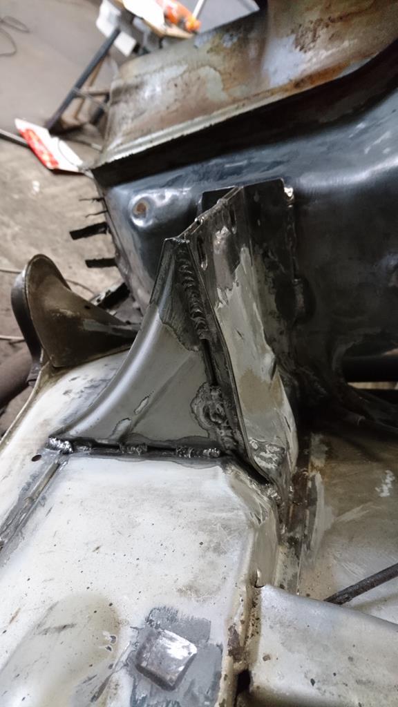 Next up I wanted to add some strength to the rear shock mounts as I'll be using coilovers and being about a 0.6:1 motion ratio the coilovers end up with some pretty firm rates. I'd deliberately brought the cage's rear legs down onto the boot floor directly above the shock mounts so it was an easy task of bridging the gap between the shock's bracket and the floor above it. Before (other than some cleaning up): 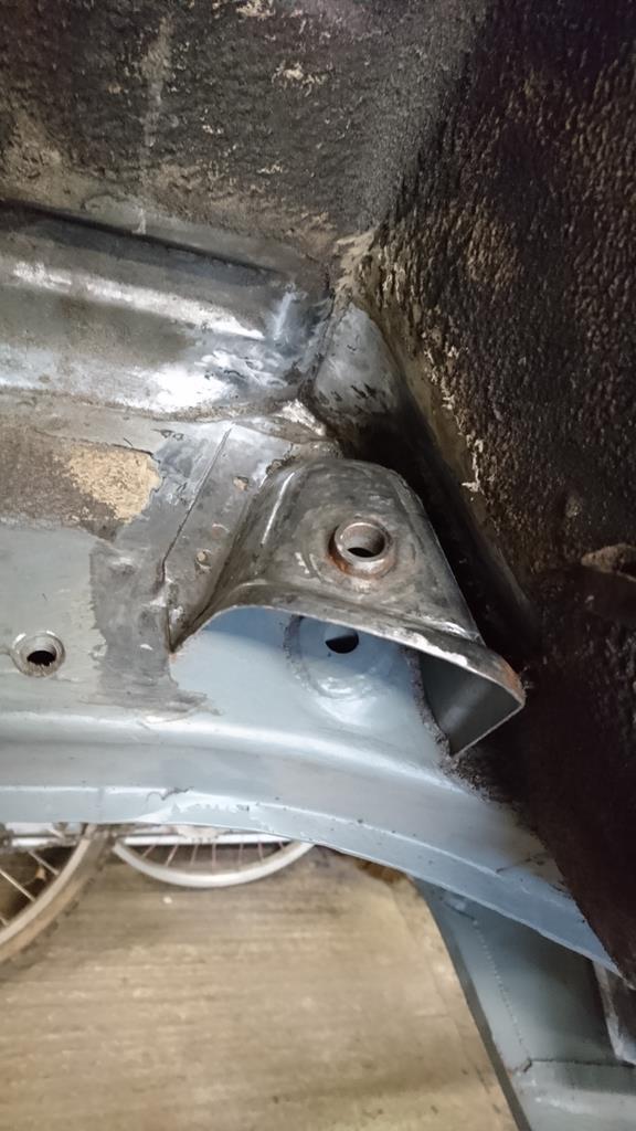 Some 3mm plate cut out and bent: 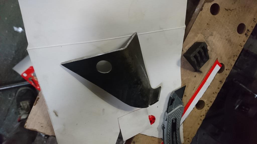 In Place: 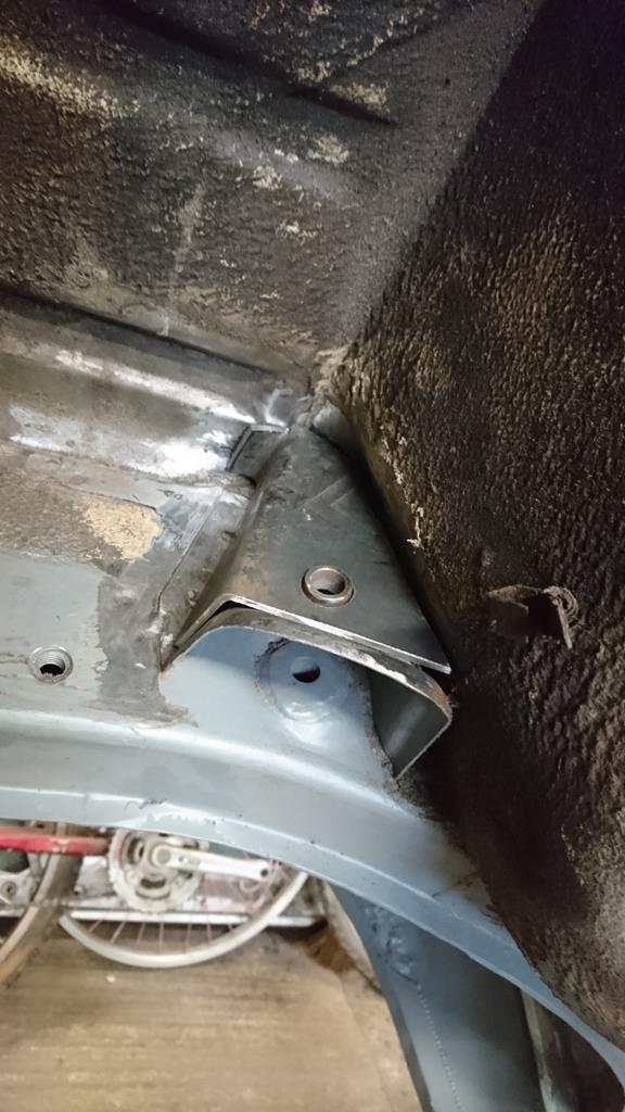 Hot-metal glue-gun'd: 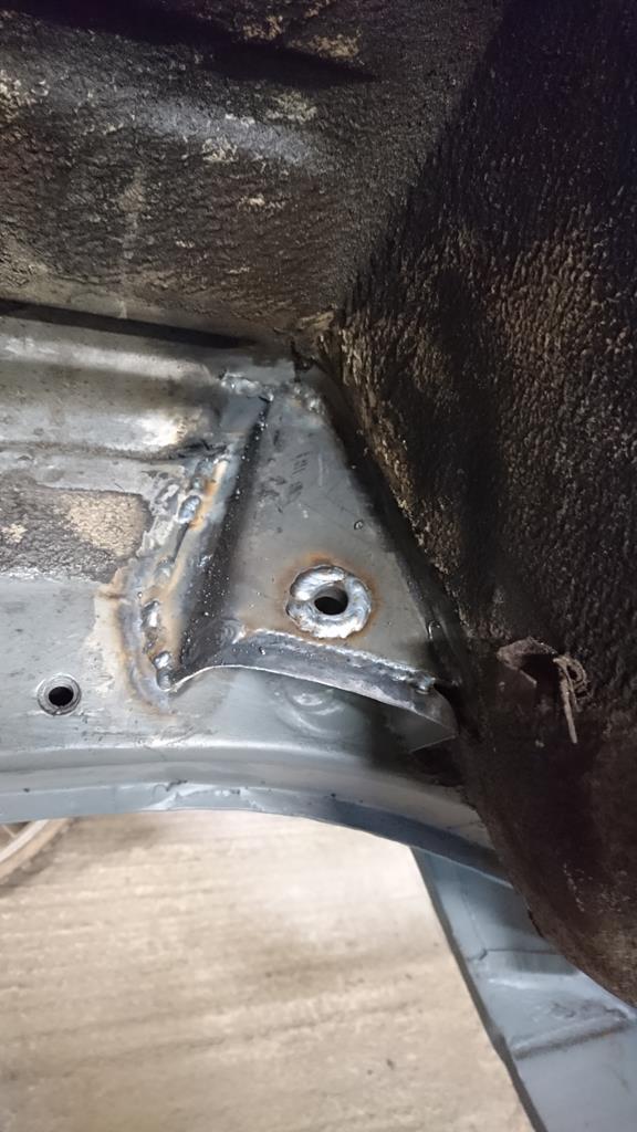 A friend had commented on a bit of cut-up pedalbox that was in my 'offcuts' bin looking too good to scrap and it got me thinking that actually it's a ready-made start to hydraulic handbrake, so I cleaned up the cut edges and trimmed off any unnecessary bits: 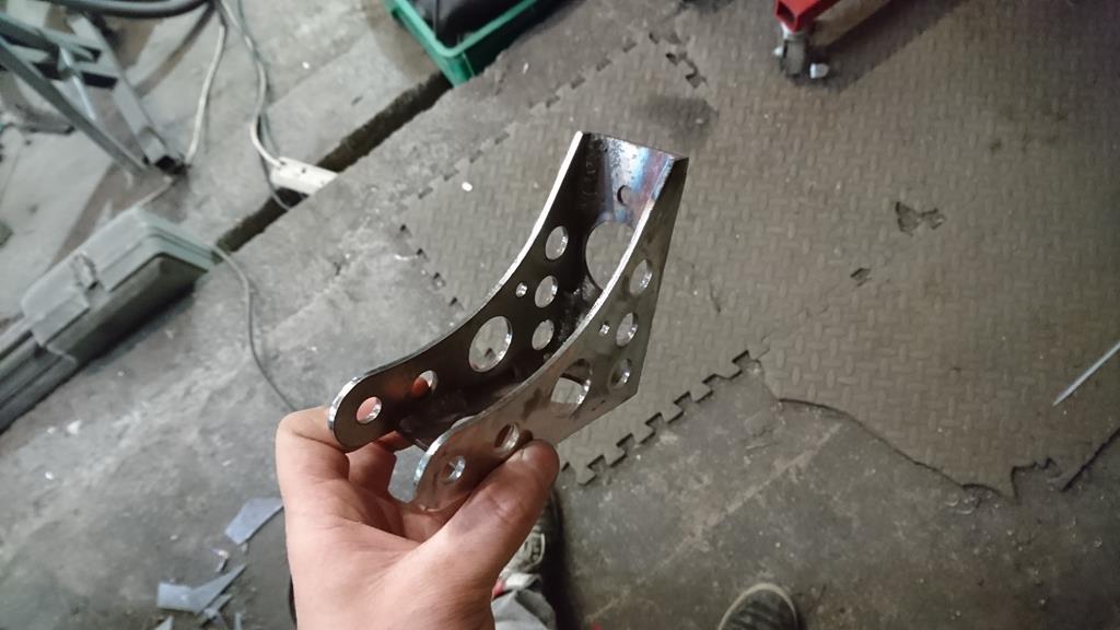 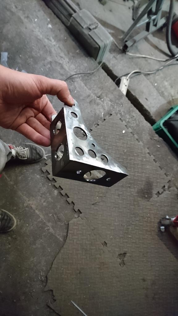 Just need to work out where's best to fit it so I can make a handle to suit and some mounts. |
| |
Last Edit: Aug 27, 2018 21:43:57 GMT by RobinJI
|
|
RobinJI
Posted a lot
"Driven by the irony that only being shackled to the road could ever I be free"
Posts: 2,995
|
|
Aug 23, 2018 22:14:46 GMT
|
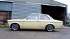
This project hasn't quite died as the lack of posting might suggest, I've just had a pretty busy summer and I'm still trying to get to grips with the whole work/hobbies balance with the new(ish) job. It's amazing what an impact loosing a little over an hour from your evenings can have. In the few occasions I've squeezed in some work, the master cylinder mounting plate's been fully welded into the bulkhead and I've been working on generally cleaning up and zinc priming any final grotty areas to get it closer to paint. I've removed the heater box and the last few bits of sound deadening from the bulkhead too. Before I actually throw any colour at it I need to make and weld in mounts for a hydraulic handbrake, gussets for the rear shocks upper mounts, brackets for a front strut brace and add back in a 4th pedal style footrest. I'm sure I'll come up with a few other items as well as countless new holes to drill and old holes to weld up, so I'm swaying towards doing a dry build getting everything in place and working before dismantling it all for paint. The risk comes if/when I decide I'm bored of not driving it and don't want to take it back apart! Anyway, here's how the engine bay's looking half cleaned up, you can see the master-cylinder mounts in place too: 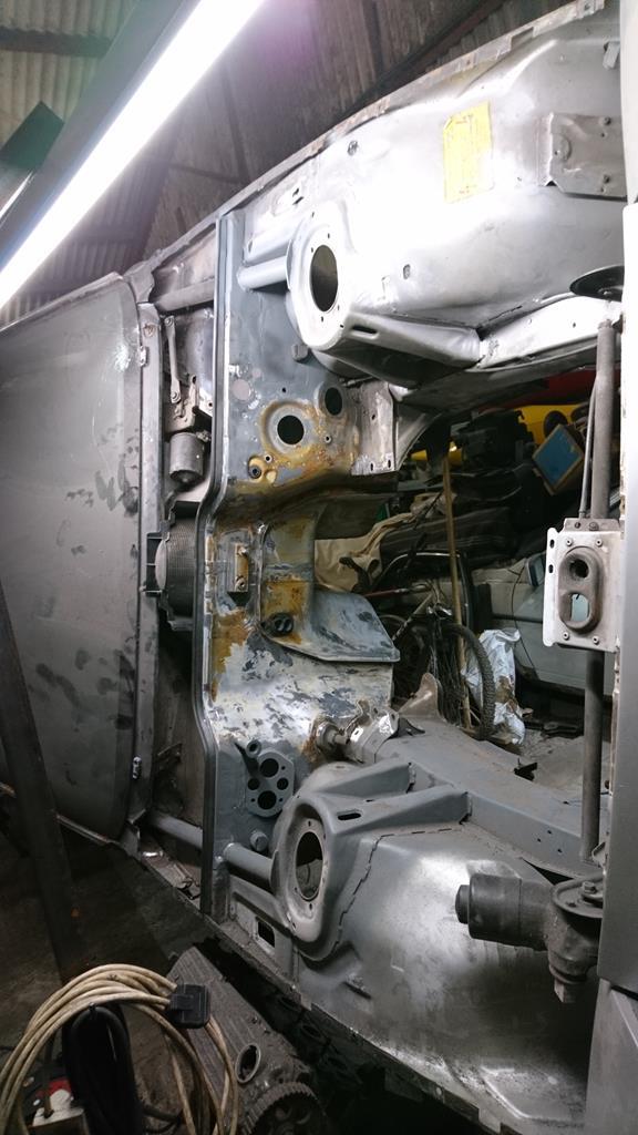 And a terrible shot of the interior: 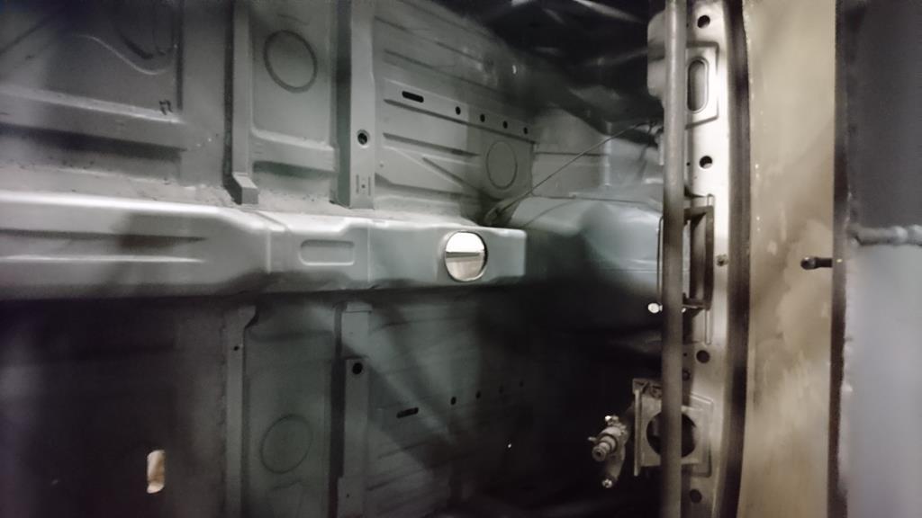 I'm off to spend a fortnight driving down the US east coast in two weeks, which I'm hugely looking farward to but sadly means I'm not expecting much progress in the next month or so! |
| |
|
|
RobinJI
Posted a lot
"Driven by the irony that only being shackled to the road could ever I be free"
Posts: 2,995
|
|
|
|
|
Very cool to see this is on the road! Such an awesome project for the two of you to have done and got going.
Our local motor club does a series they call 'grass skills'. It's essentially just a course of cones set out in a field one evening a week through the summer while there's enough daylight in the evenings. Very chilled out and a few of the regulars have let their kids have a good go at it. If somewhere local to you did something similar I'd imagine it would be a perfect chance for Tom to have a play around in the fug.
|
| |
|
|
RobinJI
Posted a lot
"Driven by the irony that only being shackled to the road could ever I be free"
Posts: 2,995
|
|
Jul 31, 2018 17:55:09 GMT
|
|
If it's polyester based then the size of the mix will effect how fast it cures. A bucket of the stuff will cure much faster than a test-tube of it due to the heat generated during its exothermic curing process not having anywhere to go. When I used to work with fibreglass, if we were worried about cure time we used shallow dishes with polyester resins to increase the surface area and let it loose its heat more easily; it definitely slowed things down compared to the deep tubs we'd use when time wasn't an issue. No idea if that's useful food for thought or just teaching you to suck eggs!
Great work on the car by the way! I've been lurking for a while enjoying the build. It'll be a fantastic car and testament to your skills when done.
|
| |
|
|
RobinJI
Posted a lot
"Driven by the irony that only being shackled to the road could ever I be free"
Posts: 2,995
|
|
|
|
Well, life went a bit crazy with moving house and a big project due at work, so the 924's been neglected a little. I have managed to get a couple of evenings to finish swiss-cheese-ing the clutch pedal and begin getting the pedal box integrated into the shell. One drilled pedal, the slightly uneven spacing of the holes bugs me a bit, but it started with some holes already so I couldn't space then out quite right: 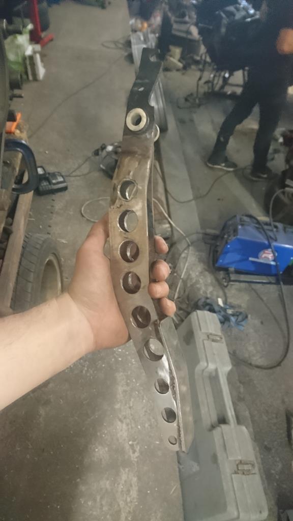 Then I knocked this little lot up: 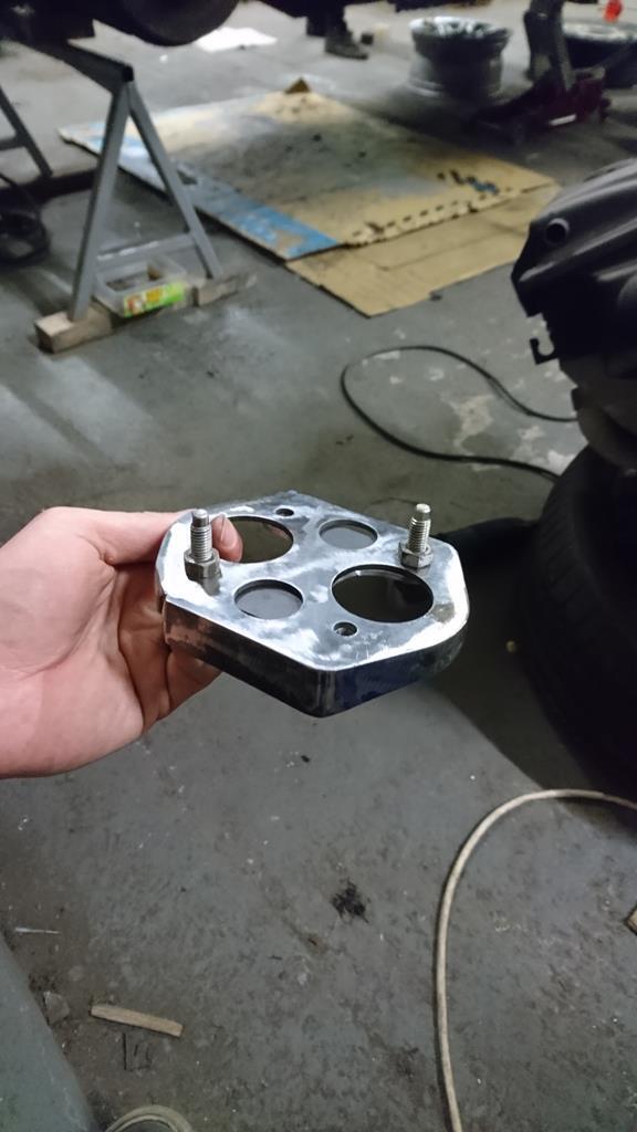 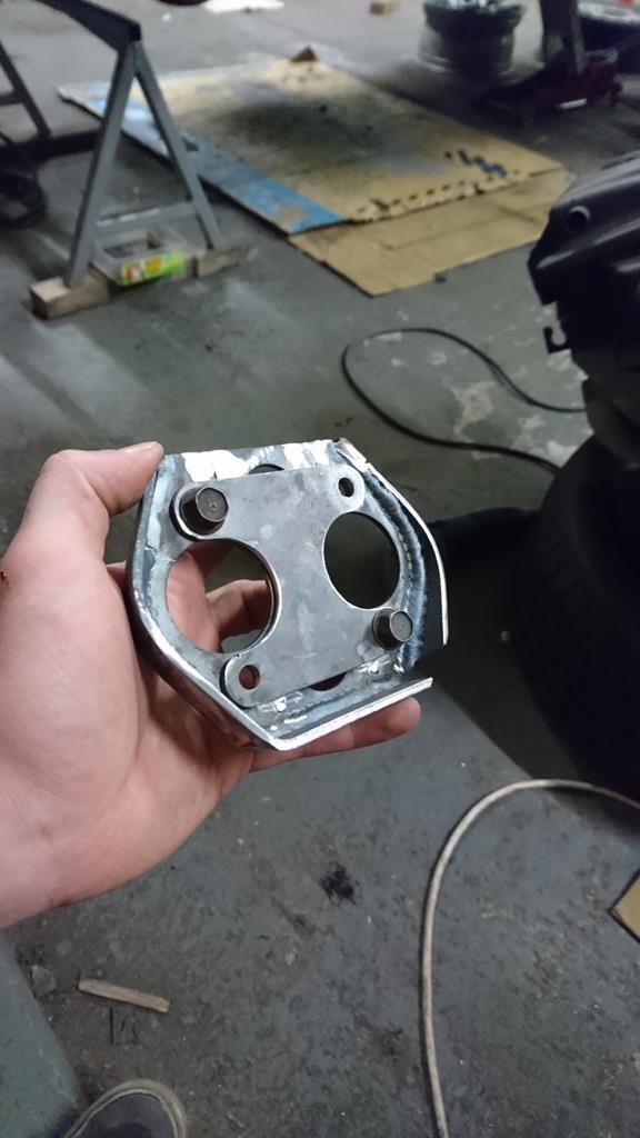 The outer piece will be welded into the bulkhead in front of the pedal box like so: 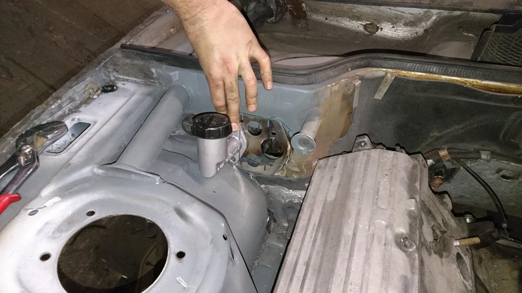 Then the inner piece will be welded to the pedal box its self with studs in it. This will keep the pedal box removable but also keep the master cylinder bolted directly to it, to keep the force-path clean and minimise flex. |
| |
|
|
RobinJI
Posted a lot
"Driven by the irony that only being shackled to the road could ever I be free"
Posts: 2,995
|
|
May 24, 2018 18:27:47 GMT
|
|
Not sure what bolts you're using on the turbo, but the bolts backing out is a common issue with the k04 turbos on 1.8t 20v engines when running aftermarket manifolds. If I remember right, the best solution seems to be A4 stainless bolts with nordlocks. The way I understand it is the thermal expansion matches better which helps them not back out. Having said that, I can't remember if your manifold's stainless!
PS, good to see you at the weekender. The car looked awesome and it was great to see it make it there, let alone see it get one very well deserved prize!
|
| |
Last Edit: May 24, 2018 18:29:12 GMT by RobinJI
|
|
RobinJI
Posted a lot
"Driven by the irony that only being shackled to the road could ever I be free"
Posts: 2,995
|
|
Apr 29, 2018 19:58:42 GMT
|
Thanks for the tip James. I may well give that a go. Work's been crazy so no physical progress, but this did just happen 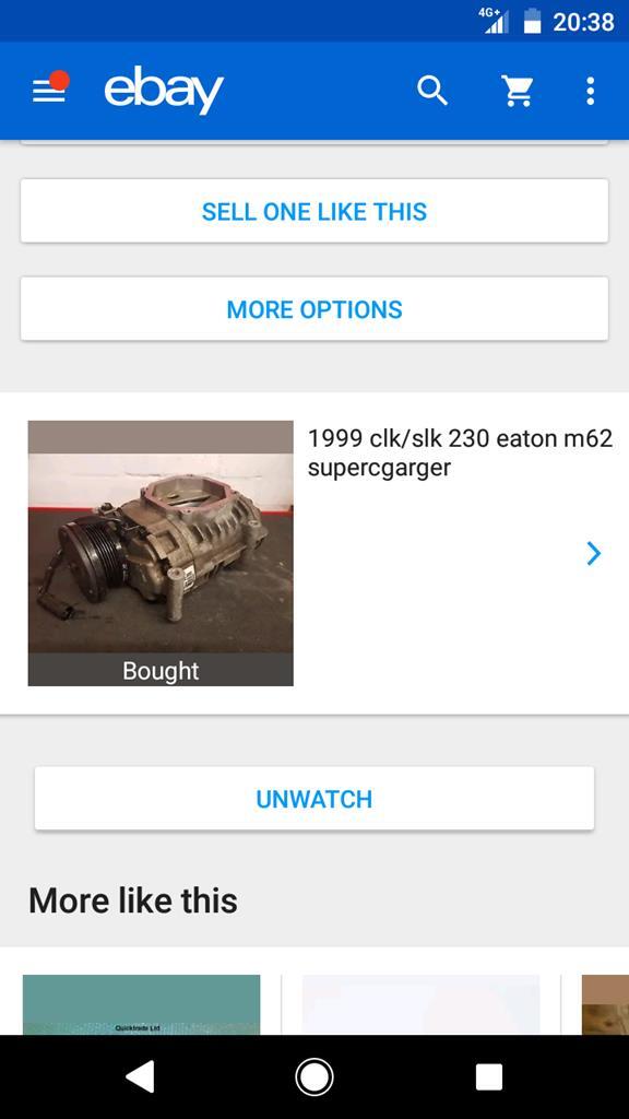 Spotting a well priced M62 on eBay finally got me to do the sums to confirm my suspicion that an M45 was a bit small, so all being well I'll have that M62 soon and can start thinking about the engines layout, bracketry and pipe-work. |
| |
Last Edit: Apr 29, 2018 19:59:12 GMT by RobinJI
|
|
RobinJI
Posted a lot
"Driven by the irony that only being shackled to the road could ever I be free"
Posts: 2,995
|
|
|
|
As above, I've found that shade 9/10 works well for mig-welding thin stuff. Recently one of the welders at work got me to try out a decent non-auto-darkening mask and it was great! So much more clarity and a much better view of what the pool's doing. Any welding I've done at work since has been done with the fixed mask and its really not been too much of an adjustment getting used to the neck-flick. It impressed me enough that I've got one on order at the moment. In some situations it can be a pain and I'll still be keeping my auto-darkening mask for the odd time when I'm upside down trying to get in a foot well or something. If you're on a budget it's definitely worth considering a good fixed mask over a cheep auto darkening one. Oh, the one I've been using at work and now have on order is one of these. rover.ebay.com/rover/0/0/0?mpre=https%3A%2F%2Fwww.ebay.com%2Fulk%2Fitm%2F232607498644I can't find a supplier in the UK so I've gone ahead and ordered from the US. |
| |
|
|
RobinJI
Posted a lot
"Driven by the irony that only being shackled to the road could ever I be free"
Posts: 2,995
|
|
Apr 21, 2018 22:07:17 GMT
|
Thanks for the feedback guys. I'm not really sure what conclusion to make from it though, so I've just gone with 'I like it when things match'. I popped out to the unit the other day to be greeted with an unpleasant surprise: 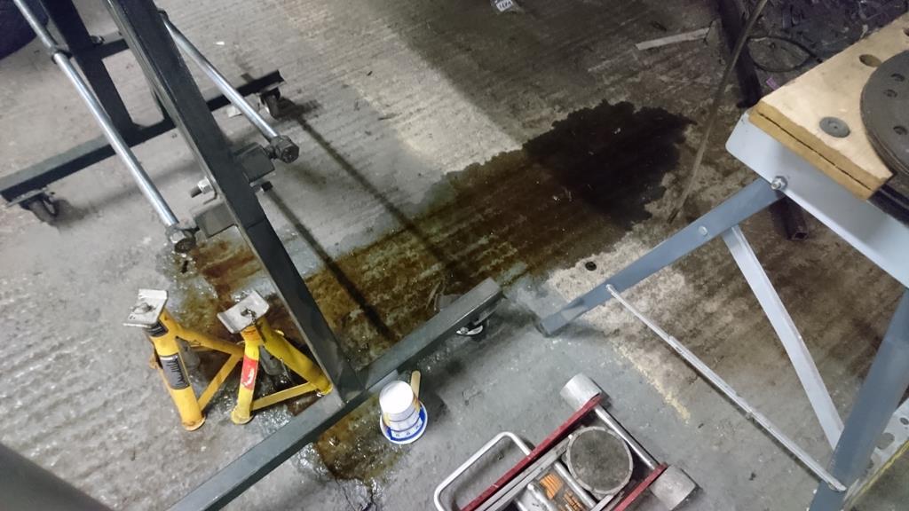 Yep, my bare shell had leaked smelly oil all over the floor.  Ahh.. That's right, I fitted the gearbox, torque tube and an old block & sump to take some measurements for the front subframe design. Ohh, and gearboxes have oil in them, and they have breathers on top of them, and I left the car completely upside down. Well.... Cock. 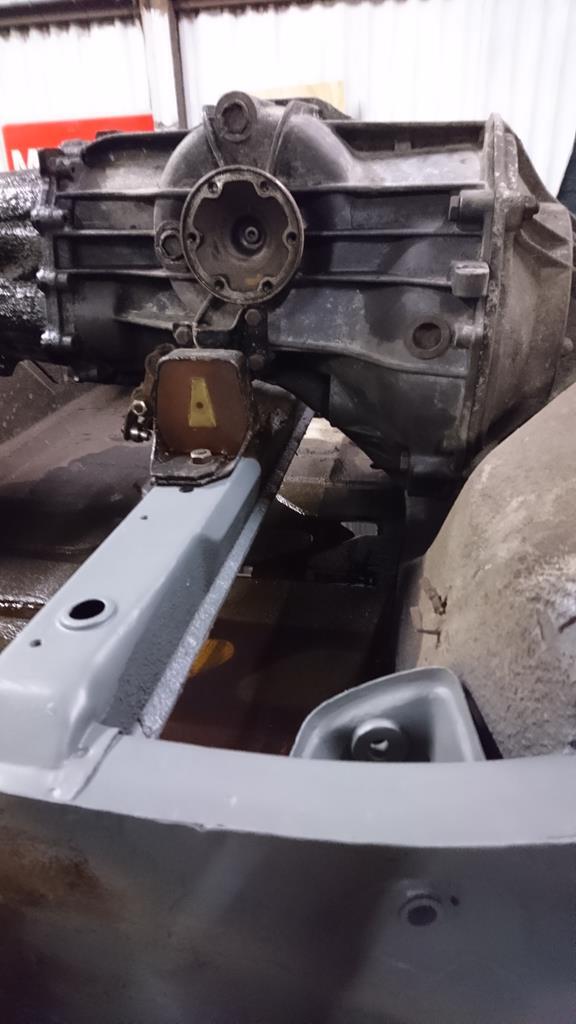 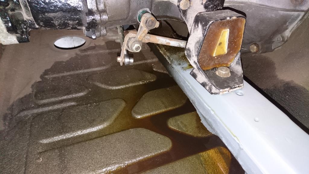 For now I'm going to choose to ignore this and carry on with the pedalbox. Adding some width: 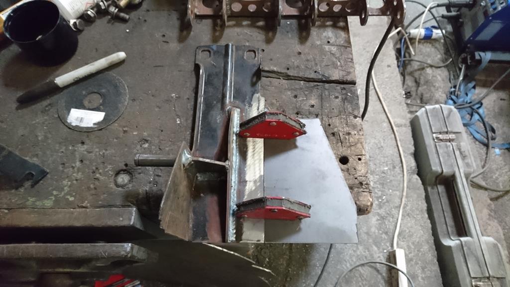 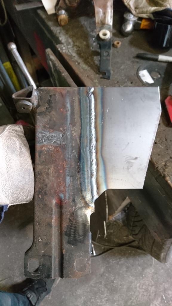 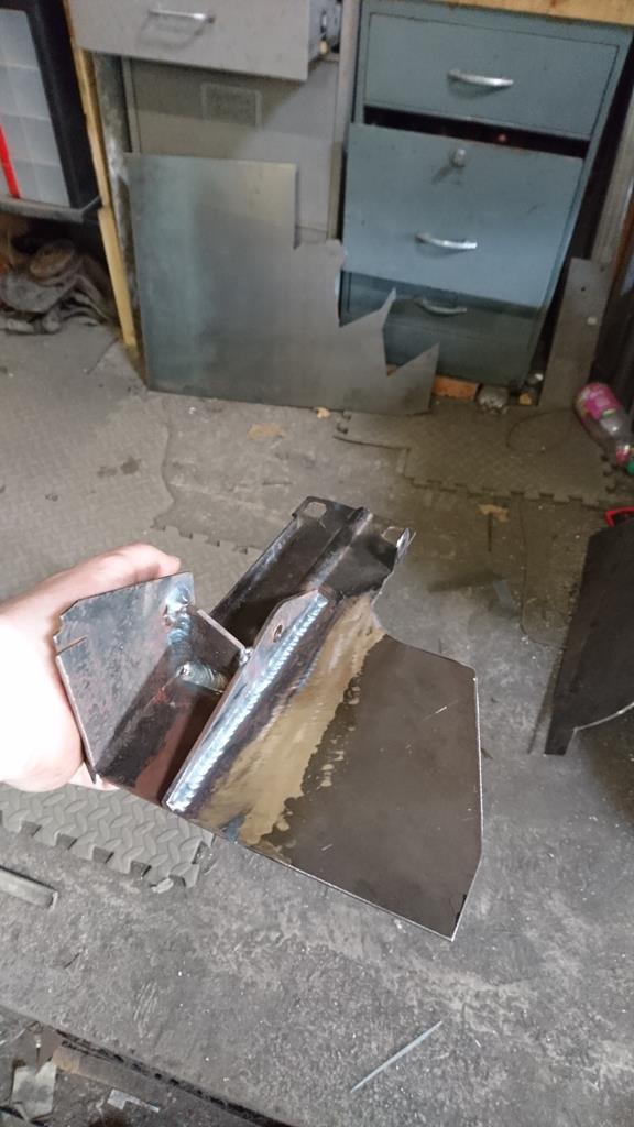 To make sure I got the throttle pedal in line with the others I tacked an old off-cut to all 3 foot-pads (is that a real name? it sounds like one), then cut the pivot end off the old throttle pedal I started out with: 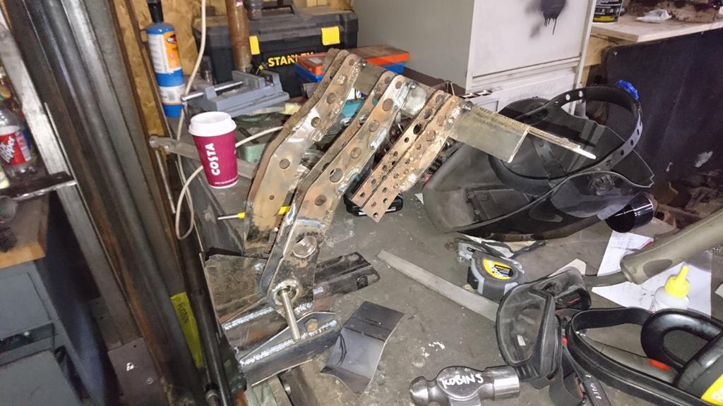 I measured a few cars around the unit to see what their pedal throw and throttle cable movement was then picked a pivot point that should give me enough adjustment to work with pretty much anything I fancy connecting it to: 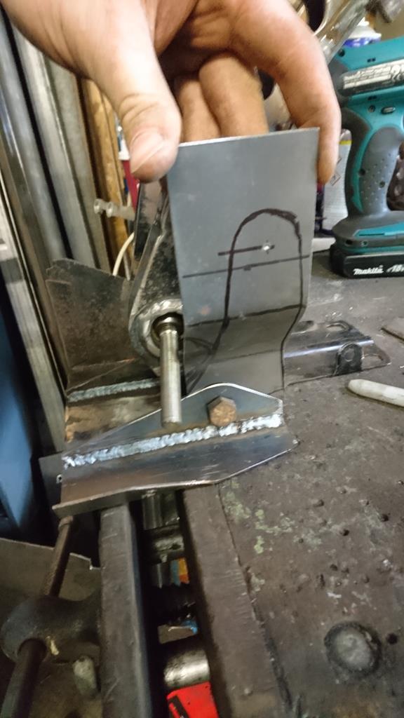 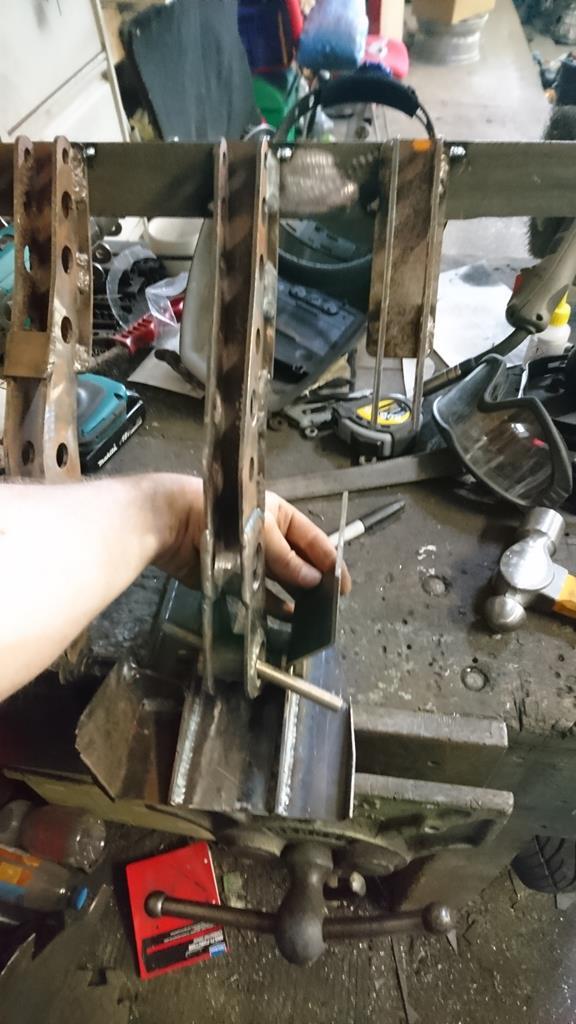 You may notice I'd also added the other half of the brake pedal pivot before this point. At this point I basically forgot I had a camera and just cracked on with the throttle pedal and its mount, so now I have this: 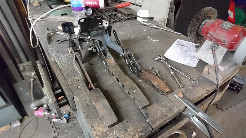 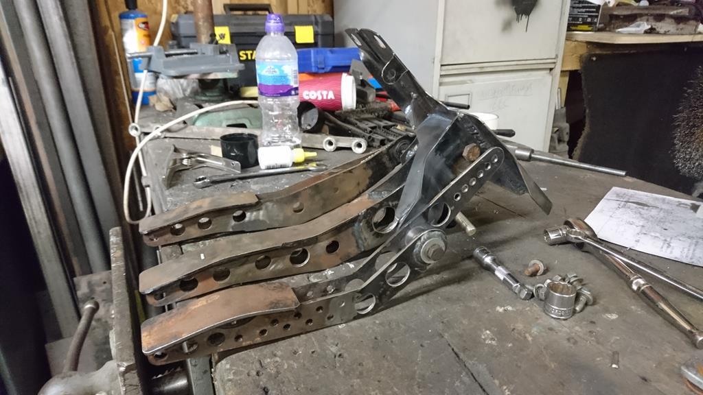 I need to turn up a bush for the throttle pedal and then I'll be onto mounting the master cylinders. Also, in shiny new stuff news 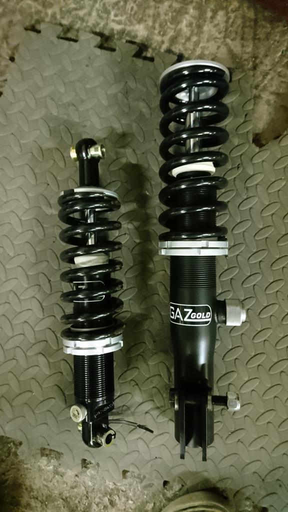 Some very nice new suspension turned up from Gaz (a week and a half sooner than expected!). They look ideal, and are another great step towards the car rolling. Now I've measured them up properly they'll be getting boxed back up and put to one side for a while until I'm at that stage. |
| |
|
|
RobinJI
Posted a lot
"Driven by the irony that only being shackled to the road could ever I be free"
Posts: 2,995
|
|
|
|
Yesterday I popped out and finished off the brake pedal, knocked up a matching clutch pedal and made a start on butchering the pedalbox to suit the new brake set-up. One pair of bushes and one pivot tube ready to be welded up: 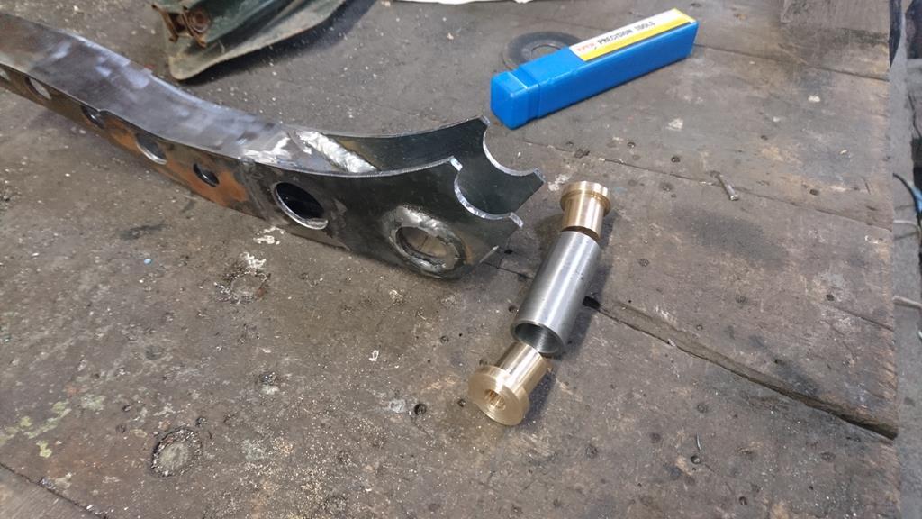 The original clutch pedal would have worked just fine as I'm keeping the factory clutch set-up, but it wouldn't have matched the brake pedal, so clearly it had to go under the knife. In a rare case of sense, I did decide to use what the factory made for the top half as it'll work just fine. 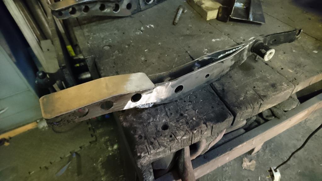 Knowing what needed to be mounted into it, I could then made a start on butchering the pedal box to fit the new brake pedal, while retaining the clutch pedals pivot. I forgot to get any before pictures but it's a simple enough thing. Essentially just a plate bolted to the underside of the scuttle with 3 sides folded down and a couple of pins sticking out of the down turns for the pedals. The brake pivot was in about the right place, but only in single shear. It originally supported just one end of the long tube that transferred your jab at the pedal over to the passenger side where the servo and master cylinder lived. Without that long tube supporting things it's design wasn't nearly man enough, so, as usual, it's time to remake things. A little chopping and welding later and I've got this: 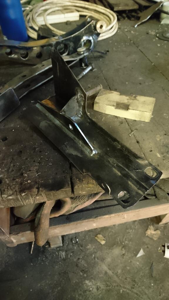 That's the clutch pedal mounted and the first side of the brake pedal mount welded on. I'll need to add another mount for the other side of the brake pedal and make up some form of mountings to the shell, as some of them were in the way of the new cylinders push-rod's path so had to go. That gives me something like this: 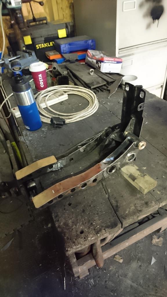 The pedals look like they're not inline but they're not in their at-rest positions, and as the pivots don't match (one's pushing, ones pulling and space is tight) they can only match at one point, like this: 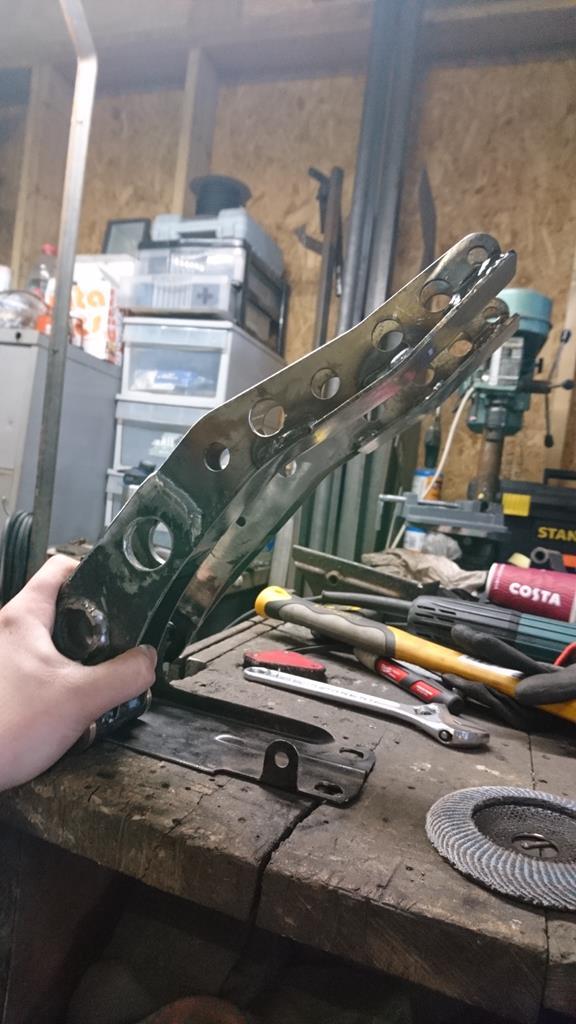 The next decision is the throttle pedal. Obviously it has to match the other two pedals, so the factory one won't do. However I'm not sure whether to keep a factory style bottom pivoting pedal, or hang a top mounted one from the pedal box along side these two. |
| |
Last Edit: Apr 8, 2018 8:49:55 GMT by RobinJI
|
|
|
|


 . Can't wait to see these come together.