|
|
|
Nov 23, 2012 19:06:29 GMT
|
|
That thud was my jaw hitting the floor.
My flabber is well and truely gasted .......
I don't have enough patience to even think about doing that type of thing.
|
| |
|
|
|
|
Seth
South East
MorrisOxford TriumphMirald HillmanMinx BorgwardIsabellaCombi
Posts: 15,543
|
|
Jan 21, 2013 12:28:38 GMT
|
Cheers optimus. Back to mechanical things, here's another recent task I had. The escapement in a clock/watch is the part that regulates the speed which the whole thing 'goes' at. The oldest form of escapement is the verge dating from the very beginning of mechanical timekeeping. Developments in the 18th century superceded it but it was still in use into the third quarter of the 19th. In a watch the verge staff is quite fragile and easily broken by mishandling. I've only had to make a few so I'm no expert and this one was quite a challenge as it is very small for a verge. There are several methods but this is the one I was originally shown. Steel of the appropriate diameter in a collet in the lathe and a pivot turned on the end to suit the bottom pivot hole. 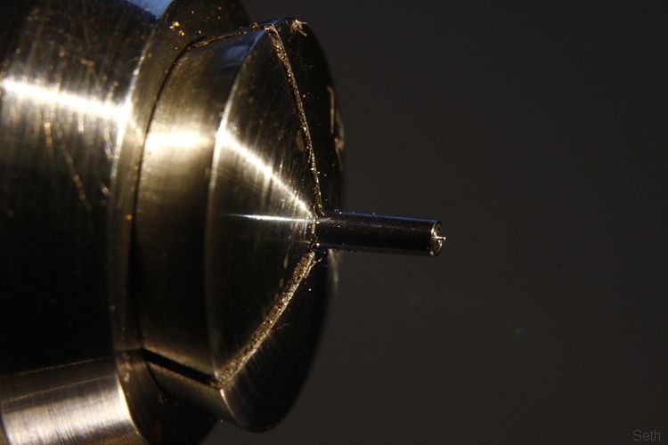 Flats are then filed. 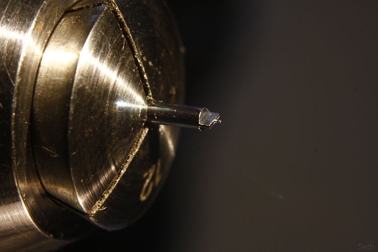 Half of that section is then filed and rounded off to leave a 'flag'. The next area above this is turned down, I leave a wafer thin wall so that the cutting tool doesn't snag on the flag. The 12 on the collet obviously refers to the size, the raw material in this case being 1.2mm diameter. 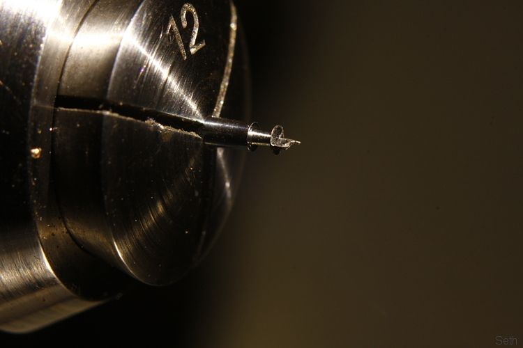 I remove the wafer section by filing and the shaft is turned down to diameter about as thick as the flag. 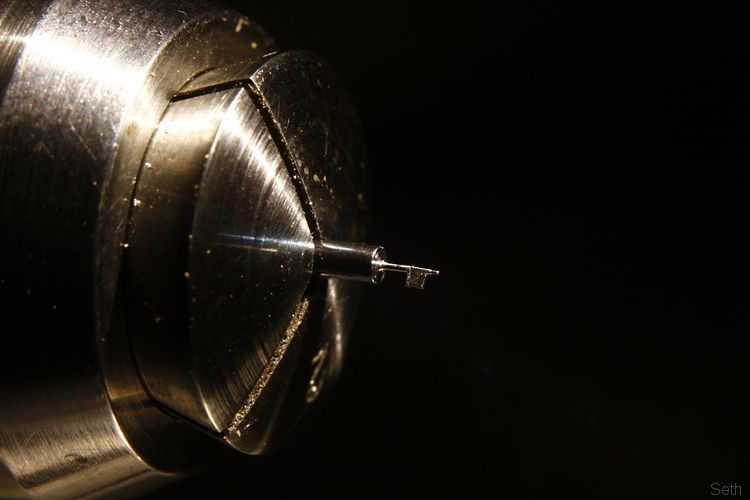 The working surface of the flag actually needs to be roughly on the centre line of the shaft. A wooden support is used while the top surface of the flag is reduced. Previously I have always used files for this but as this one was so small after some experimentation I found it easier to scrape the material away with a graver. 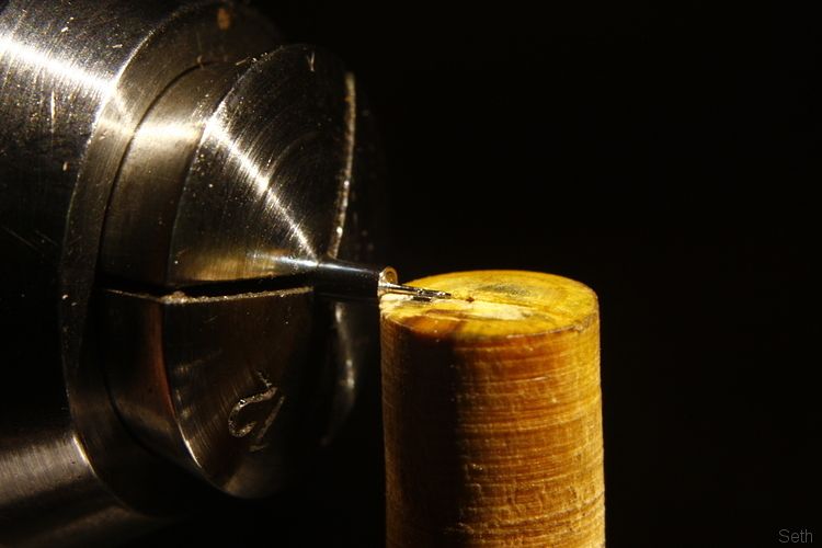 Here is that flag basically finished. As you can see I've nicked the shaft slightly - I did say I was no expert. These would have originally been made by people who did nothing else but make verge staffs and so would have turned them out perfectly and quickly. 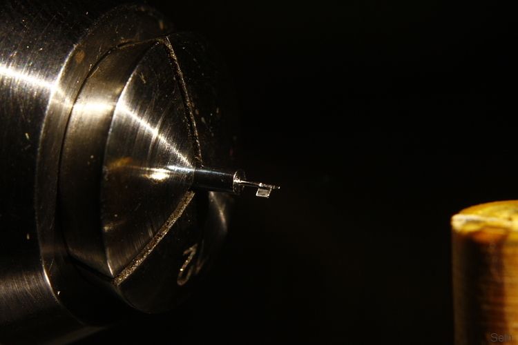 The its time to do it all over again with the top flag. This is formed at ideally a little more than 90 degrees from the other one. No more than 100 O though. An indexing ring on the lathe headstock helps will filing this at the right angle. Its trickier to file too as the other flag gets in the way and catching it with the file means a bent staff and likelyhood of starting all over again. The flags are also chamfered on the back edge and mirror polished on their faces. Much use is made of the wooden support for this. 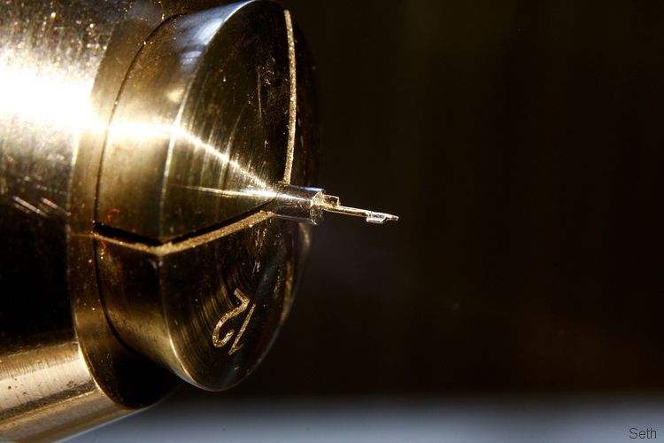 With the flags done the next section is turned to the right size to suit the hair spring collet. Enough material is allowed for above this and the staff parted off. 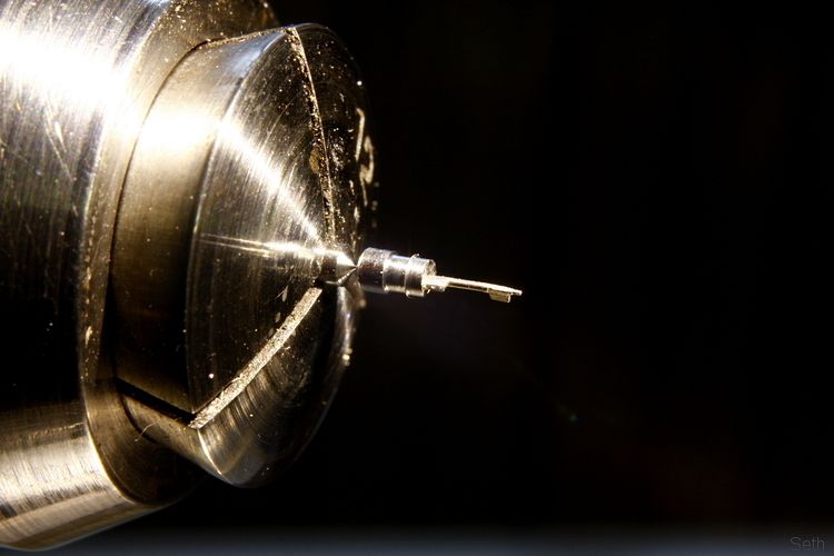 With the staff round the other way in the lathe the seat for the balance wheel and the top pivot is made. 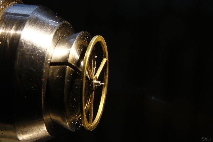 There is lots and lots of trial fitting to get things just so. Here you can just see the top pivot of the verge in its hole. It needs to sit just below the surface of that recess into which a piece of steel is retained as a thrust surface, allowing for a tiny amount of endfloat. 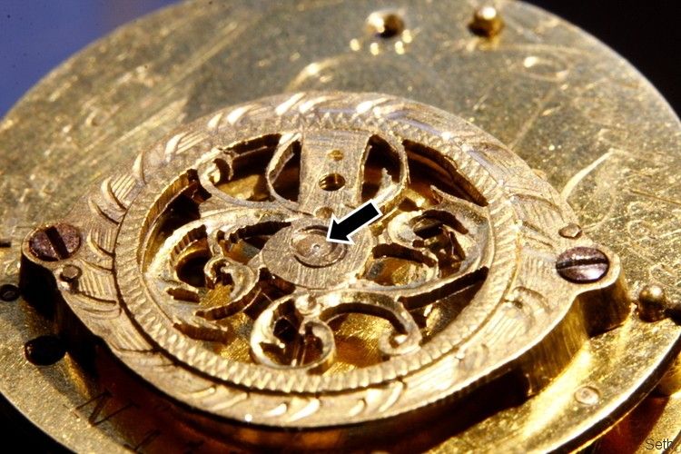 Here's the view from the other side. The arrow is pointing at the upper (second) flag, the staff passing behind the brass section which is jutting out into a hole at the top in this image, the blue steel piece being the thrust surface at this end. 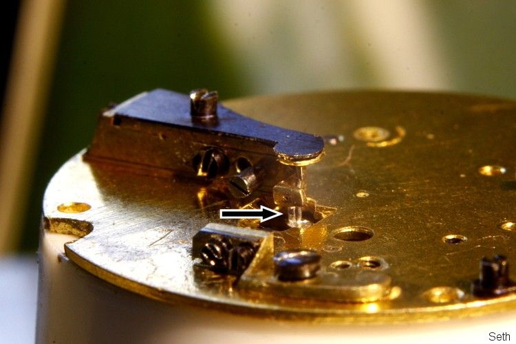 The balance fully assembled with with the staff and hairspring looks like this. You can see why they are fragile. In this case the distance measured with a micrometer from the tip of a flag to the back of the shaft is just under 0.5mm. 'Scuse the bit of hairy dust. 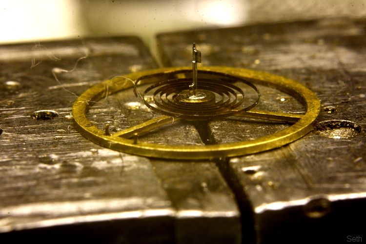 And then with it all assembled and the movement running you can barely see any of it. 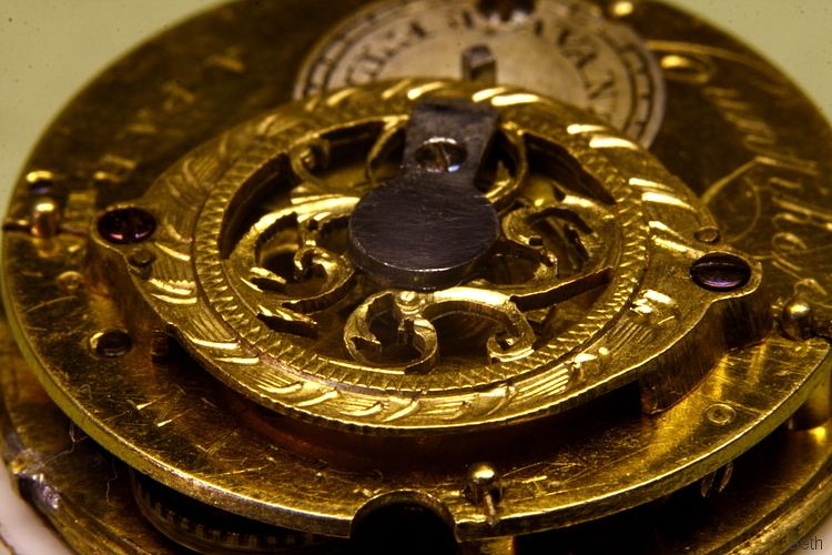 |
| |

Follow your dreams or you might as well be a vegetable. |
|
bmw156
Part of things
 
Posts: 796
|
|
Jan 21, 2013 12:36:15 GMT
|
|
Thats just epic. I cant think of other words for it. So small
|
| |
|
|
|
|
|
Jan 21, 2013 16:11:43 GMT
|
I love this thread, makes the impossible seem possible  I like the fact that I cannot believe how small these are and how you produce something so tiny and yet they were designed and made many years ago when 'technology' was supposed to be less advanced. Great work as usual Seth. John. |
| |
|
|
Seth
South East
MorrisOxford TriumphMirald HillmanMinx BorgwardIsabellaCombi
Posts: 15,543
|
|
Jan 21, 2013 20:21:20 GMT
|
I like the fact that I cannot believe how small these are and how you produce something so tiny and yet they were designed and made many years ago when 'technology' was supposed to be less advanced. There were some pretty talented people back then. 'Lathes' would have been driven using a bow in one hand and the cutting tool held in the other, generally turning between centres. The thing that gets me is that they would have been doing this work in very poor light and I don't know what sort of magnification devices they used, probably just an eye glass. But there was more division of labour in watchmaking than any other industry and so many people who specialised in only one element of making a watch and could make that bit or carry out their specific task very well. |
| |

Follow your dreams or you might as well be a vegetable. |
|
|
|
|
Apr 10, 2013 23:20:36 GMT
|
|
Id been thnking of doing some work experience in this sort of engineering. I'm studying aero engineering at the mo.
This thread has made me want to do it even more. Truly inspirational. Thanks Seth.
|
| |
|
|
Seth
South East
MorrisOxford TriumphMirald HillmanMinx BorgwardIsabellaCombi
Posts: 15,543
|
|
Jun 12, 2013 13:52:05 GMT
|
Hadn't seen your post Bruno. Good luck with it! This week I have mostly been making stuff to help make stuff. One of the reasons why the inside of a watch looks so sparkly is because many parts are polished dead flat. To get something nearly flat is not that hard. To get it absolutely flat, with no drop off at the edges etc is really tricky. I have a specific part to make for a watch which will need polishing and if I can do it well will likely lead to more similar work which is highly specialised and quite well paid. To that end I have finally got around to making what is called a swing tool. Basically its a swivelling device for holding the part being filed such that flatness is easier to maintain. Some time ago I picked up this frame at a horological fair (think autojumble with old clocks and watches) for a couple of quid to use asd the basis of my swing tool. It probably would have been originally used for turning something specific between centres. There's no markings on it, it might even be home made but was well finished having been gilt. At a guess it is probably somewhere around 100 years old. 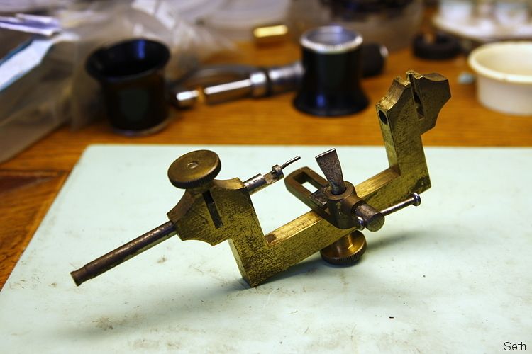 Its incomplete, missing a spindle and clamp. I found an old brass thumb nut and a brass screw that matched the existing clamps. I made up a new clamp using some brass offcut silver soldered to a portion of the screw and swapped the nuts around. Then turned a point on to the end of a couple of lengths of silver steel rod of the right size. 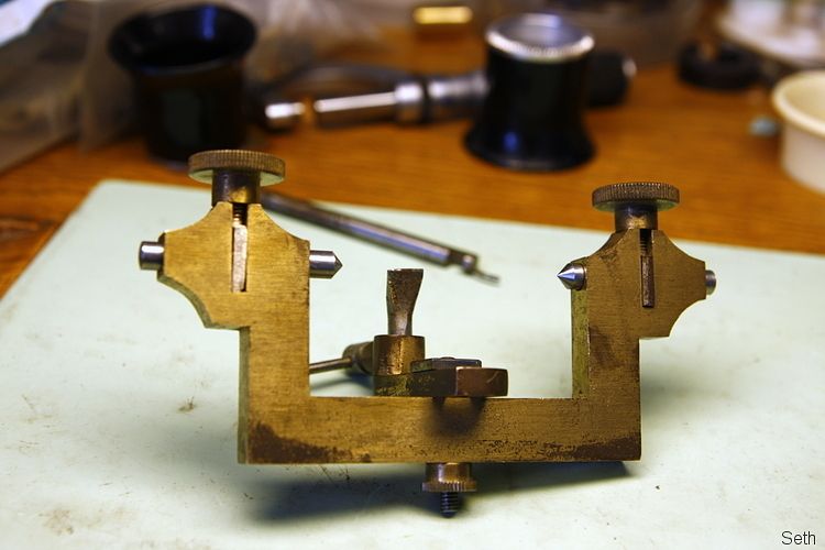 Having sketched out what I wanted to make (I was using a single drawing in a book as a guide) I chopped up, milled and filed some ground-flat-stock. 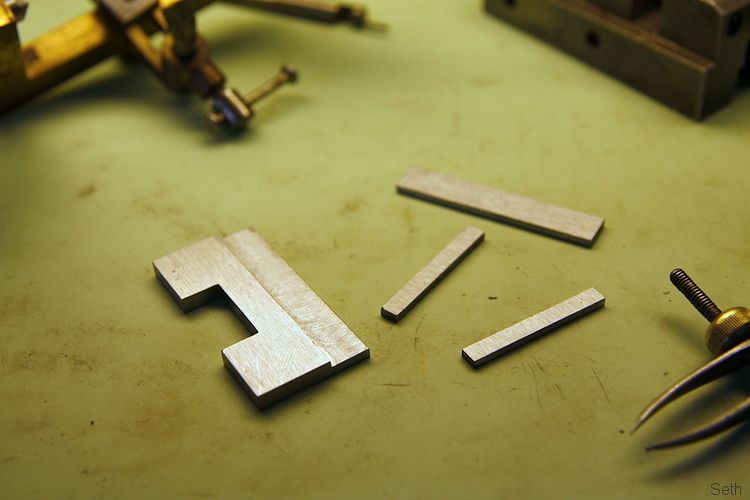 A couple of slots were milled in the skinny side plates for height adjustability using my wobbly big machine. Other holes drilled and tapped as necessary (mostly 10BA) 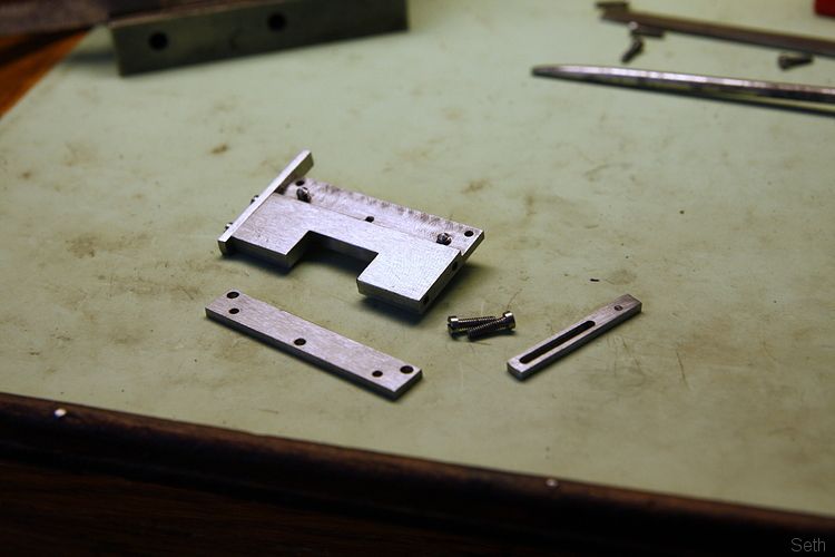 Put it all together and this is what it looks like. The three screws on the front clamp the part between the jaws. There are two on the back to adjust the width of the jaws at the bottom to allow the jaws to close on the part roughly parallel. The clamp assembly can be adjusted up and down using the two screws each side as it is best if the surface being filed is level with the pivots. The adjustable T rest in the centre may or may not be of use but I figured that if I could make the swinging element to clear it then at least I'd have the option of using it. 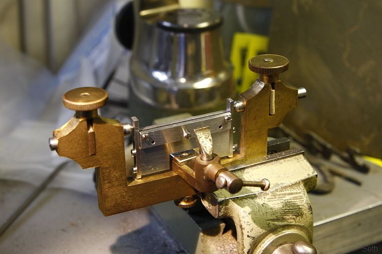 This shows what it actually does, in exageration. As you file the arc of the arm/wrist tends to mean that the file doesn't run exactly flat. By clamping the part in a way that allows it to swing it lets it follow the angle of the file as it changes. 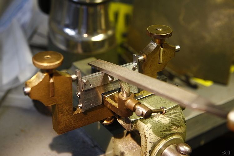 I've also made up an alternative top in place of the front jaw by soldering two pieces of flat brass into a T shape. This can be used as a 'wax chuck' on which odd shaped components can be 'glued' using heated shellac. 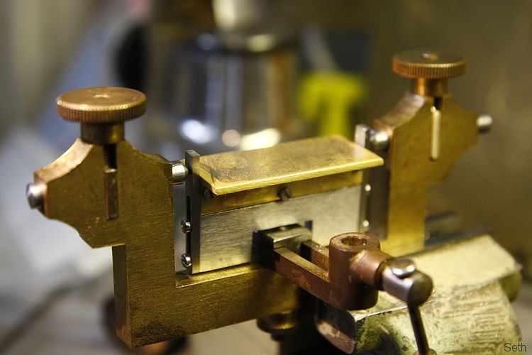 Having used GFS for the steel parts my intention is to harden and temper them but I think I'll wait until I've started using it in case I want to make any alterations. |
| |

Follow your dreams or you might as well be a vegetable. |
|
|
|
|
|
|
Jun 13, 2013 23:51:05 GMT
|
Yup.  |
| |
|
|
|
|
|
|
|
|
Kin ell!
Makes me feel like a cack handed Neanderthal!
Keep it up Seth, it's fascinating.
|
| |
Koos
|
|
|
|
Seth
South East
MorrisOxford TriumphMirald HillmanMinx BorgwardIsabellaCombi
Posts: 15,543
|
|
Jun 14, 2013 16:45:31 GMT
|
Cheers.  Here's some actual watch work I photographed as I did it a couple of months ago. Amongst other things this early 19th century continental watch needed a 'Night/Strike' lever to act as a switch to turn on/off its hourly party trick. First I used one of my current favourite bits of kit to chop off a bit of the raw material. 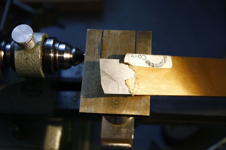 Yes, its a circular saw set up that goes in my little lathe. 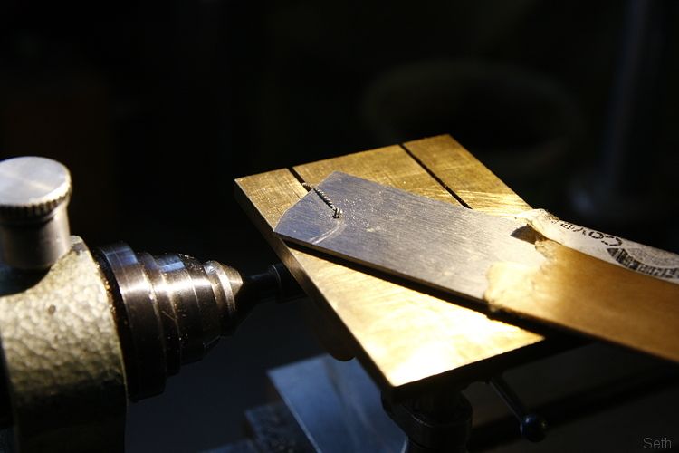 The rough shape required was scribed on to the metal and a pilot hole drilled for the pivot point. 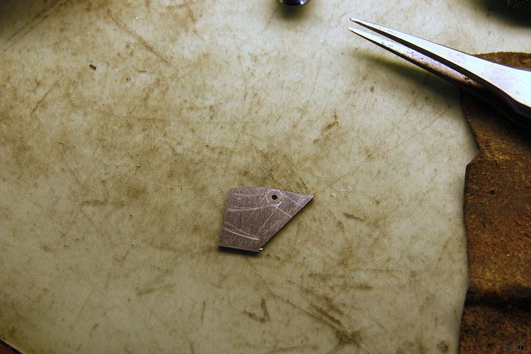 With a bit more chopping I offered it up in position. 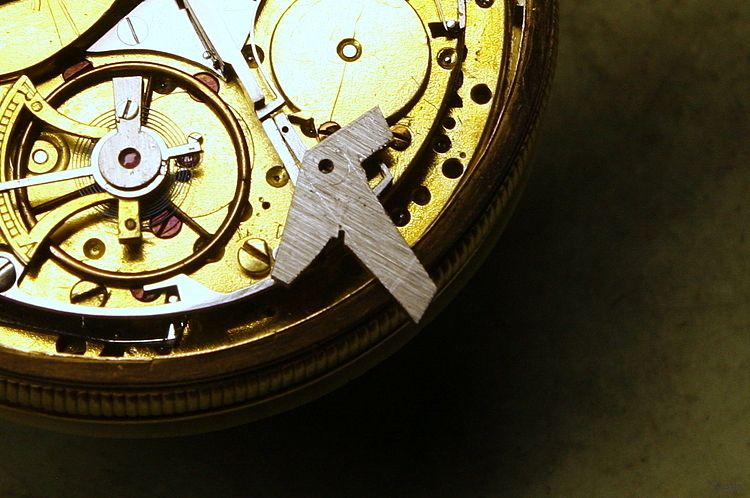 More filing got it fairly close to the final shape. 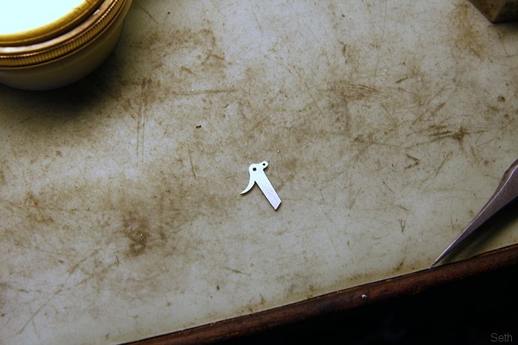 Hole drilled in the short arm to take the detent pin. This acts with the part below which is a spring to keep it the lever in one position or the other. 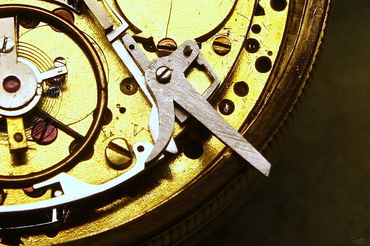 Here's the pin (made from a scew) from below. Step filed on the long arm to suit the notch in the case. 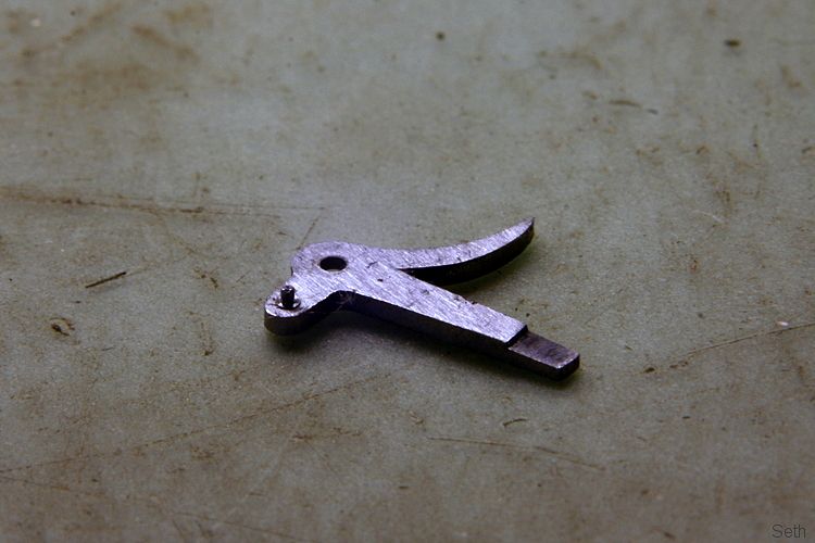 From the top, counterbore made for the pivot screw, using some small cutters I have for this purpose. 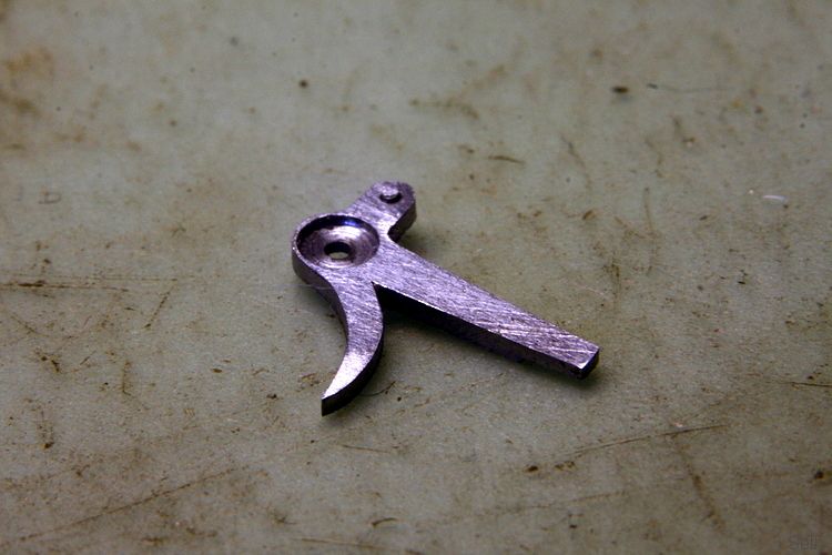 With the lever pretty much to shape I had to make the pivot shoulder screw. 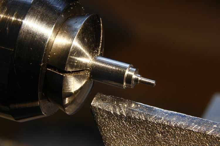 The thread is put on using a screw plate which has a series of different sized threaded holes for cutting screws. I made a couple of trial screw threads out of brass to check what would fit snuggly in the original hole in the watch. 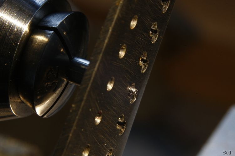 As I hadn;t yet made the swing tool, which may have been useful for this, I quickly made this little table device. Three screws with lock nuts on the back. Adjust the screws so that the part, which is glued down with shellac, is flat against a smooth surface, apply some polishing paste and then rub it on the surface. 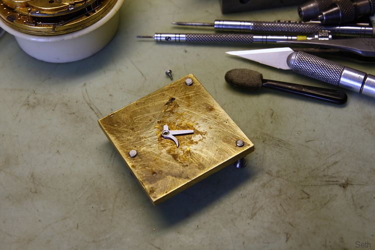 There are several stages, the first being oilstone powder (like fine valve grinding paste) moving on to diamantene.in order to try and get a perfect polished surface. 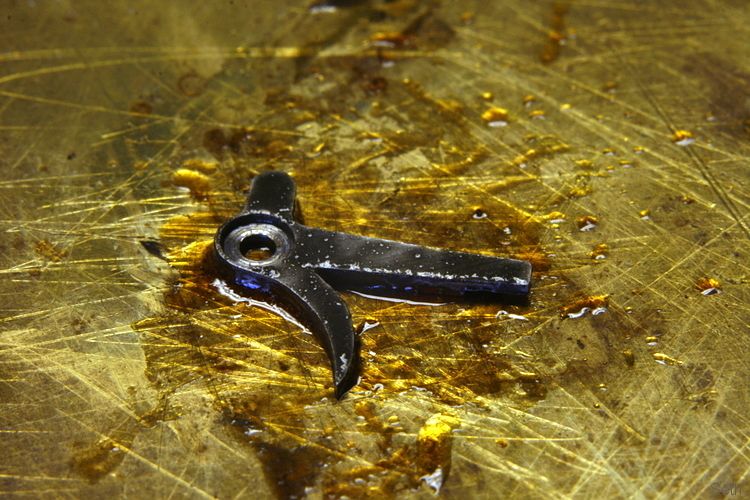 Eventually once that is done it was hardened by heating and keeping it dull red hot for a couple of minutes then quenching in oil. Then to temper I use this little pot of brass swarf, heated form below so that the part is evenly heated to the right colour (indicating a certain temperature range), removed and left to cool. 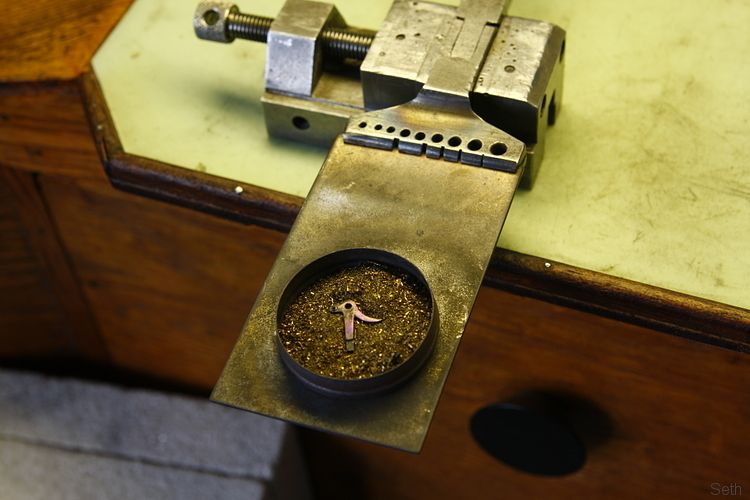 The surface then needs cleaning and re-polishing and its done. 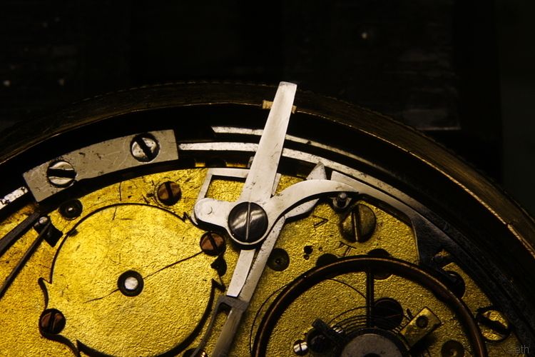 Well, nearly. The long end was shortened a little more to stop it from being knocked accidentally. |
| |

Follow your dreams or you might as well be a vegetable. |
|
MrSpeedy
East Midlands
www.vintagediesels.co.uk
Posts: 4,791 
|
|
Jun 14, 2013 18:14:16 GMT
|
|
Superb stuff as ever.
Working on big lumps of iron everyday, I sometimes find it difficult to comprehend such miniture work
|
| |
|
|
bigrod
Posted a lot
  
Posts: 1,654
|
|
Jun 18, 2013 20:14:20 GMT
|
|
Seth, there has got to be something superhuman about you! The stuff you do is absolutely jaw dropping!
Keep up the good work and keep keeping us amazed!
|
| |
If I have to explain, you won't understand.
Maximum signature image height = 80 pixels
|
|
Seth
South East
MorrisOxford TriumphMirald HillmanMinx BorgwardIsabellaCombi
Posts: 15,543
|
|
|
|
Nothing Superhuman really bigrod. Well, not like Sylar anyway.... Here's something I've been doing on and off for a while. Mostly off than on to be honest but I've decided to get it finished sooner rather than later so have picked it up again recently. I repair watch cases as part of my normal work but making one from scratch is something that I wanted to learn. I was fortunate to have a couple of conversations with a man called Martin Matthews who sadly passed away a year or so ago and was a fourth generation watch case maker using tools and techniques passed down through his family. An excellent film was made of him making a case around the year 2000, a copy of which I have, and it shows most of the processes involved. I don't collect watches as such but obviously acquire bits and pieces from time to time, one of which was a nice, good quality movement by a well known London firm which is not totally standard but incorporates a couple of nice features. Financially it would not be worth paying to case (it's only worth a few tens of pounds), but for me it would make a nice watch if I could give it a home. It would also originally have been in a half hunter case, one with a sprung hinged cover over the dial, with a small hole in the centre. You can tell this because of the double headed hour hand. So making a half hunter case would add to the complexity and challenge of the project and if successful, be a better 'show piece' for potential future business. After taking some dimensions and making some drawings I started with some metal, learning and adapting techniques as I went Making a case is mostly about making rings First up the central case band to which the movement is fitted. When trying to bend this rectangular section around the nose of my 'die' it was trying to twist out of shape so I cut a groove of the appropriate size to try and keep it more square. 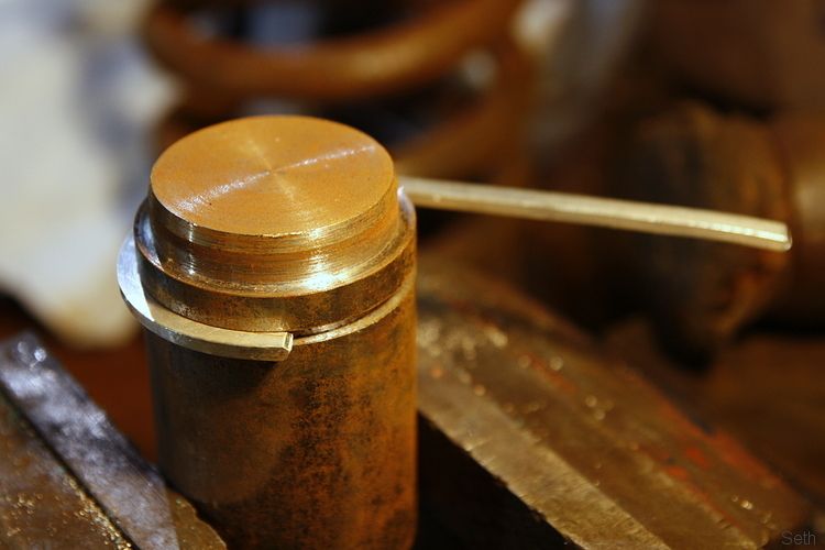 Obviously I could wrap it right around in the groove but once it was most of the way there I could finish back up at the top. 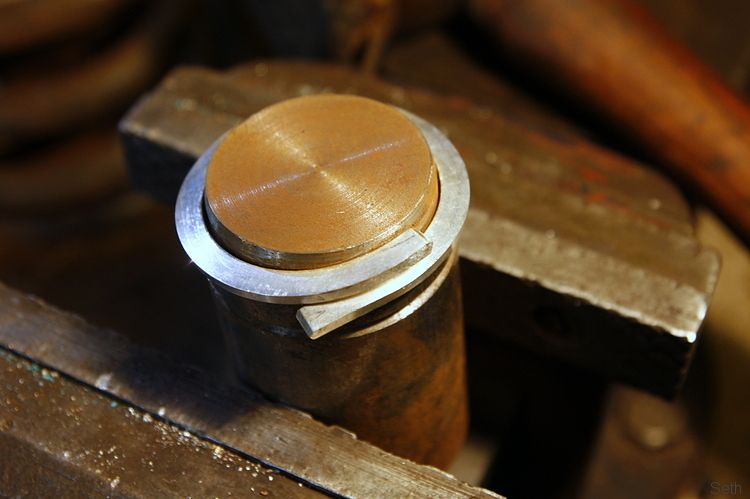 Ends were cut and make to sit together. for soldering. 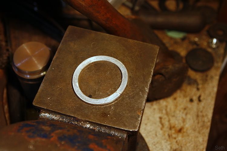 Difficult to see but its now a sold ring with the joint soldered. 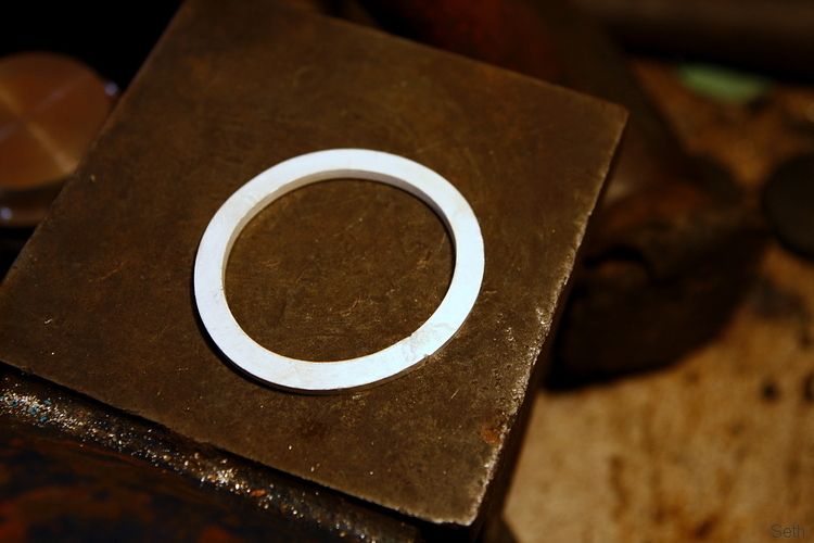 Then, having intentionally made it a little small, it can be pushed/knocked/hammered over the die to make it round and flat. 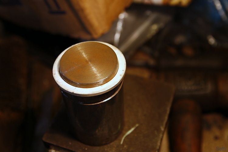 The do it again with another bit of wire. 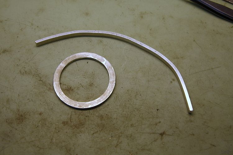 And then again with another bit, this time some 'D' shape wire, around a larger die such that the fat rings just fit inside it. 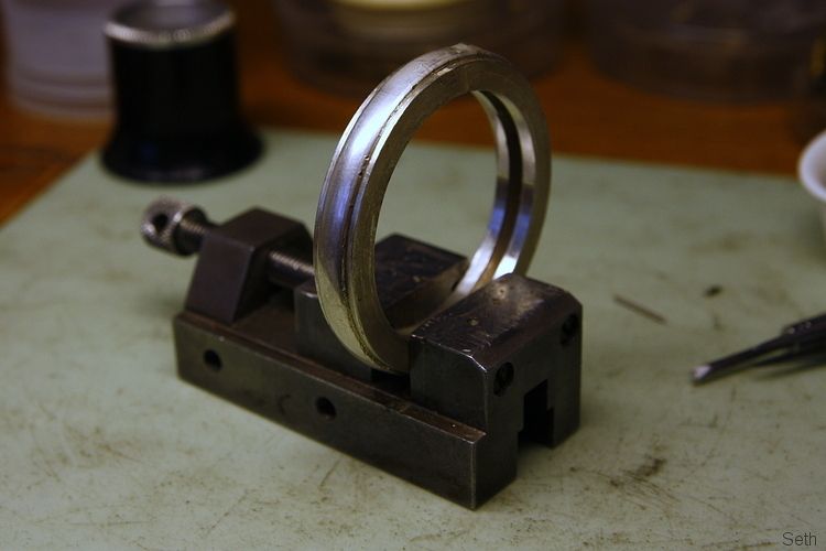 That assembly was then all soldered together to make the complete band ready for turning. The inside needs to fit the front and the back of the movement plates snuggly and then the outside has steps on to which the covers will fit. 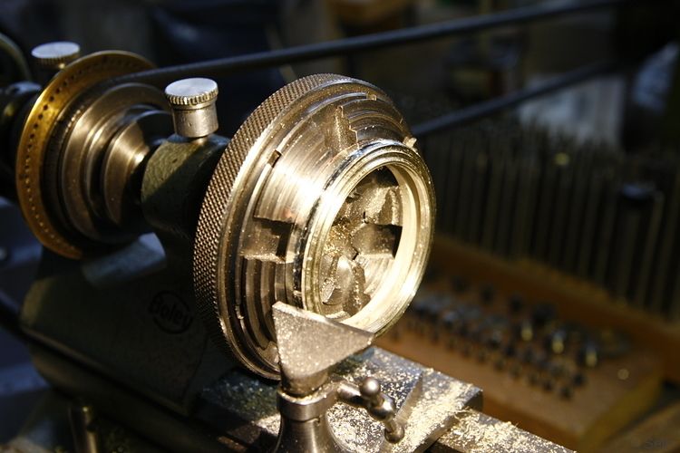 With the inside and the front turned, the movement fits in, being located by the two pins, holes for which were drilled. 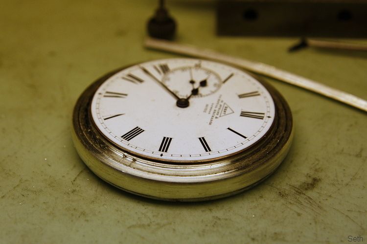 The back was still in the raw, but you can see towards the bottom where the movement retaining screw should go. 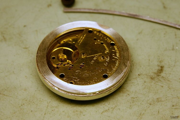 With the rear steps turned, I cut the semi counterbore in the case to suit the screw recess in the movement. 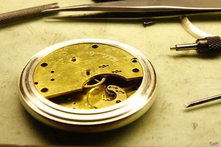 The movement can now be fixed in with the screw. 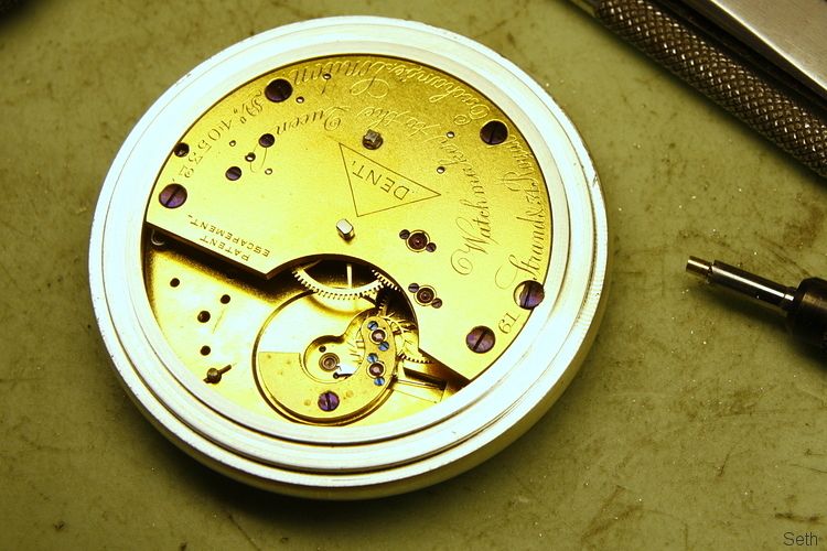 Two more rings made, (ie wrapped around steel die, soldered, made round and flat,etc) the thinner one to eventually be for the inner back cover, the fatter one the front bezel that holds the glass. 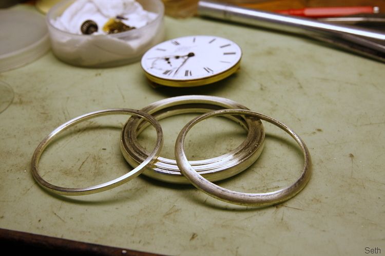 Here's the front now equipped with the bezel. 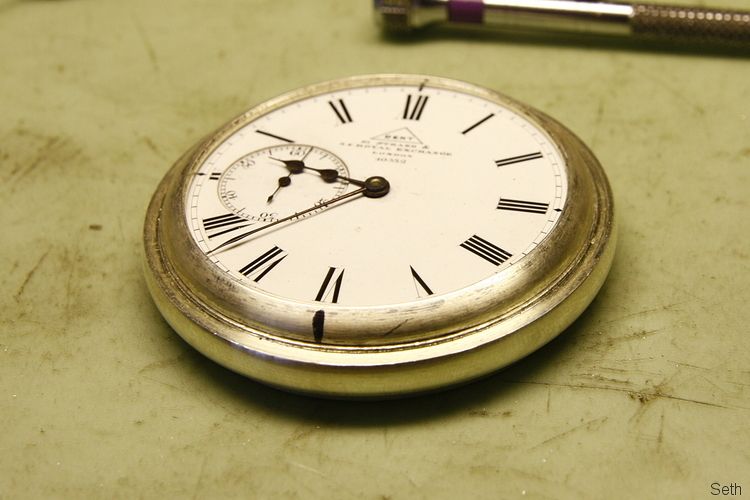 I have got a bit further with it but need to sort out some more photos before I can continue with this.really. So more anon. |
| |

Follow your dreams or you might as well be a vegetable. |
|
TS
Part of things
 
Posts: 558
|
|
|
|
|
This is great. Can we have some pics of your workbench/workshop setup? You've got fantastic looking tools and machines, especially the home made ones.
|
| |
|
|
markbognor
South East
 
Posts: 9,970
Club RR Member Number: 56
|
Assorted diddy engineering.markbognor
@markbognor
Club Retro Rides Member 56
|
|
|
|
I love seeing how you fabricate the complex shapes from simple sections of bar and sheet Seth. Fabulous stuff.
|
| |
|
|
|
|
Seth
South East
MorrisOxford TriumphMirald HillmanMinx BorgwardIsabellaCombi
Posts: 15,543
|
|
Oct 10, 2013 16:30:23 GMT
|
Thanks chaps. Tallsam, I've tended to just mention tools here as and when I've thought of something worth showing. Most of the work tends to be with basic hand tools, I suppose with the odd thing to help out with workholding etc. The small lathe is just that. Markb, Not sure if you'rre referring to the case there but to be honest I haven't managed to work out how they were mass produced. It may be that the case bands were made using some stamped sections before turning but I can't really see any joins on them. So I had to come up with my own method, using those three rings soldered together, as making from solid wouldn't really be a sensible solution or at all economic should I be asked to make one in gold at some point in the future. Here's part two of the case making, bringing it up to where I am now. I made some case backs a few years ago and perhaps stupidly wimped out from pressing the dished sections instead hammering each one from flat sheet. They came out OK but I knew I would get a better finish by stamping them by some means. So I bought a cheap bench mount arbor press and set to making a punch and a die to form the inner back. 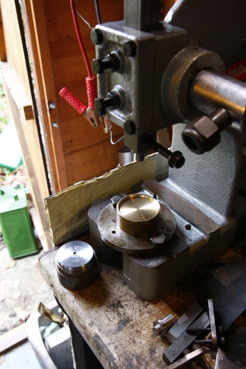 That worked OK. 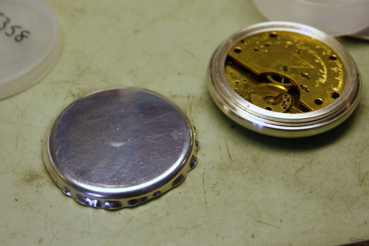 Then the smaller of the two rings mentioned in the post above was shaped to fit inside, soldered and then the excess material cut/filed off. 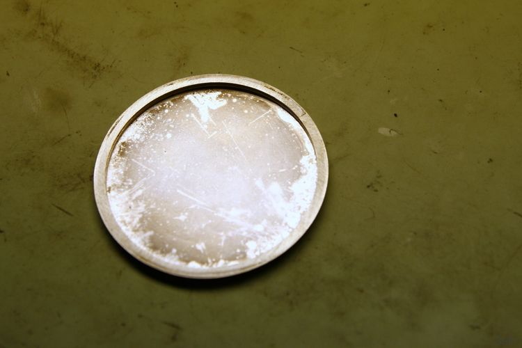 This was a bit of a hit and miss method in terms of getting the ring flat to the dish so I wanted to do the outer back and the front covers a better way. First up to make another punch and a die to suit. 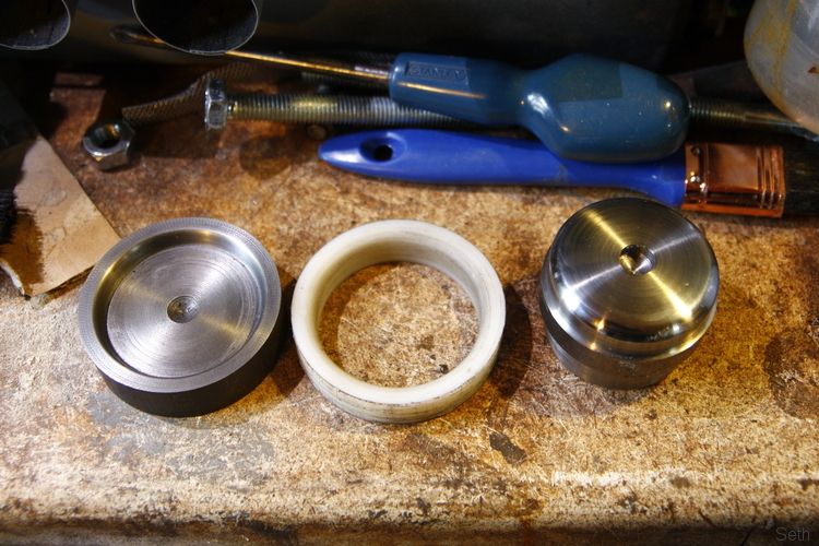 I used the metal die on the left at first to press the outer back but it wrinkled a bit much and wasn't great, requiring a bit of hand finishing over the punch. My last 'proper' job was desigining press tools so I have got a vague idea of what does what and how but its a while since I did that. I was pretty sure that a larger lead in radius on the die would help and so made the nylon one, with a bore right through so I wouldn't be restricted by depth. The punch was also slightly reduced in diameter to allow for the extra metal thickness of the front cover. 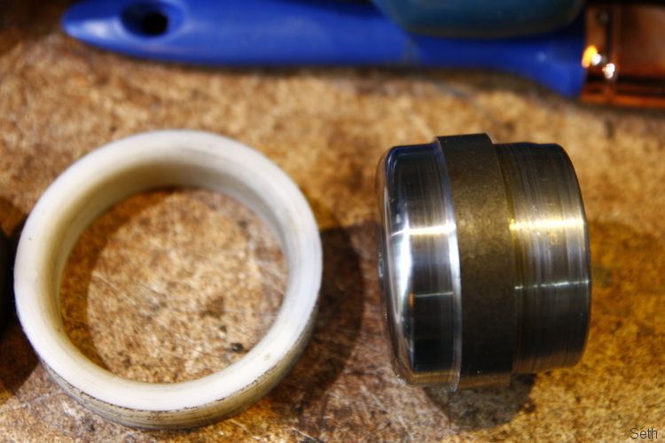 Things lined up on the press. 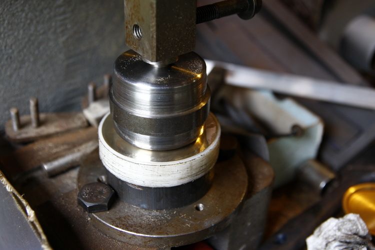 Much happier with that result. 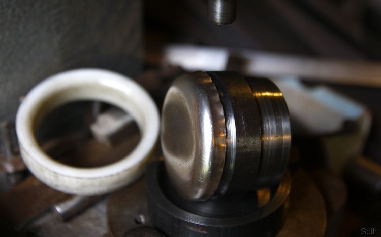 With these I reckoned a method I had seen used by Martin Matthews would enable me to remove the excess material much more reliably. I've got some bits of oak from when a tree in our garden was trimmed so I stuck a branch of appropriate diameter in the lathe and turned it round. 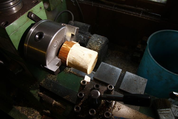 Then using a hand graver, formed an end similar to that on the punch. (the bore tool was just used as a rest) 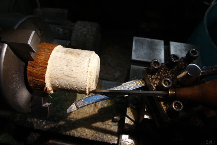 Et, voila. The metal dish pushes on nice and tight and flat. 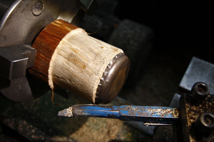 A bit of work with a parting off tool and... 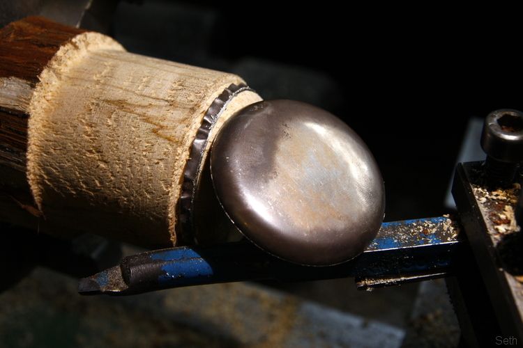 So that's where I'm at now, two dishes and two more rings. 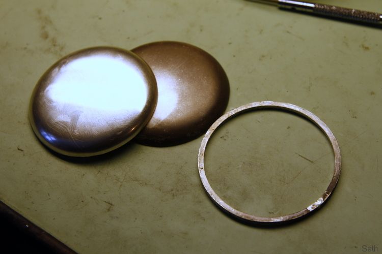 There's only one ring there though because the other is chucked in this lathe. 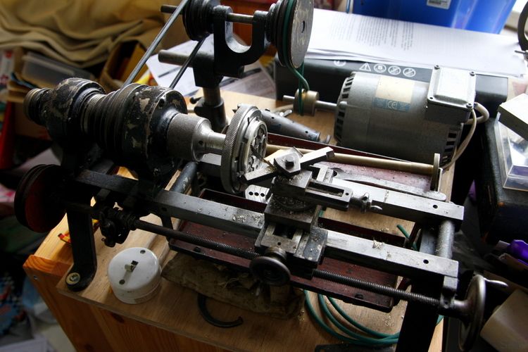 Since turning the various steps on the central band I became aware that I was using my watch lathe probably beyond its capapbilities for power. So I have cleaned this larger, almost home made, one up which I was given by a family friend a few years ago. It's not as precise as the watch lathe but a perfect size for the case work and had the bonus of coming with adapters to take the same chucks as the watch lathe. Now I've got to turn both these rings to suit the two covers and solder them on. To be continued... |
| |

Follow your dreams or you might as well be a vegetable. |
|
dw1603
Part of things
 
Posts: 591
|
|
Nov 20, 2013 22:45:57 GMT
|
Bookmarked! Love that funky drive reversal trick on your lathe, high tech doesn't come into it. The case making project is fascinating, all the more so because I had no idea how to go about it, anxiously awaiting the next update. The Night/Strike lever you did, was that a modification or a replacement? Either way, it was a nice piece of work. Regards, Dave |
| |
|
|
Seth
South East
MorrisOxford TriumphMirald HillmanMinx BorgwardIsabellaCombi
Posts: 15,543
|
|
|
|
|
Thanks Dave.
The case has progressed a bit more though I'd really like to have got it finished by now but other work has taken priority. The night/strike lever was just one bit that that movement was missing so it's a matter of taking some artistic licence and making a replacement that functions and looks appropriate.
|
| |

Follow your dreams or you might as well be a vegetable. |
|
|
|


