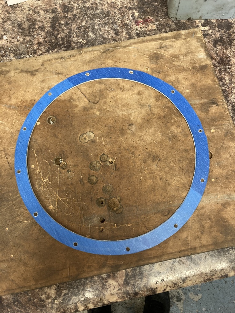
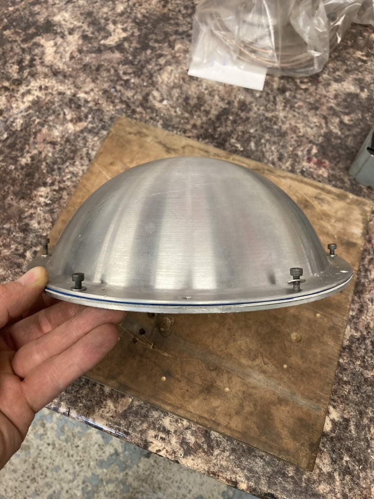
Returning back to the belt.
After making many improvements to the setup I still wasn’t 100% with it.
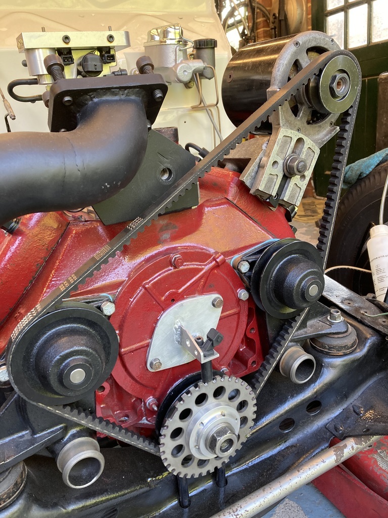
It was suggested by
jimi and
TessierAshpool that an idler may improve the situation which is of course correct and the idea had crossed my mind in the past but had gone no further.
Two reasons inspired me to expand on the idea.
First the turbo mount I fabricated gave me a large flat area to work off that was also pretty much in the middle of that long belt run and the second was that I realised that the turbo outlet actually clashed with the belt.
The outlet might not end up here but it would mean one less area it can’t be positioned in.
To find an idler.
I remembered that the Pinto had a simple idler mounted to a backing plate.
Looking these up for reference brought up another option which was even better.
A Duretec idler.
So…
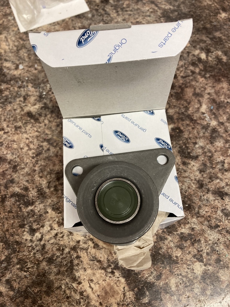
The weren’t much money but cheapest I found was direct from Ford via EBay.
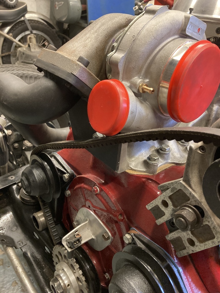
A quick mock up showed it was perfect in every way, even the spacing!
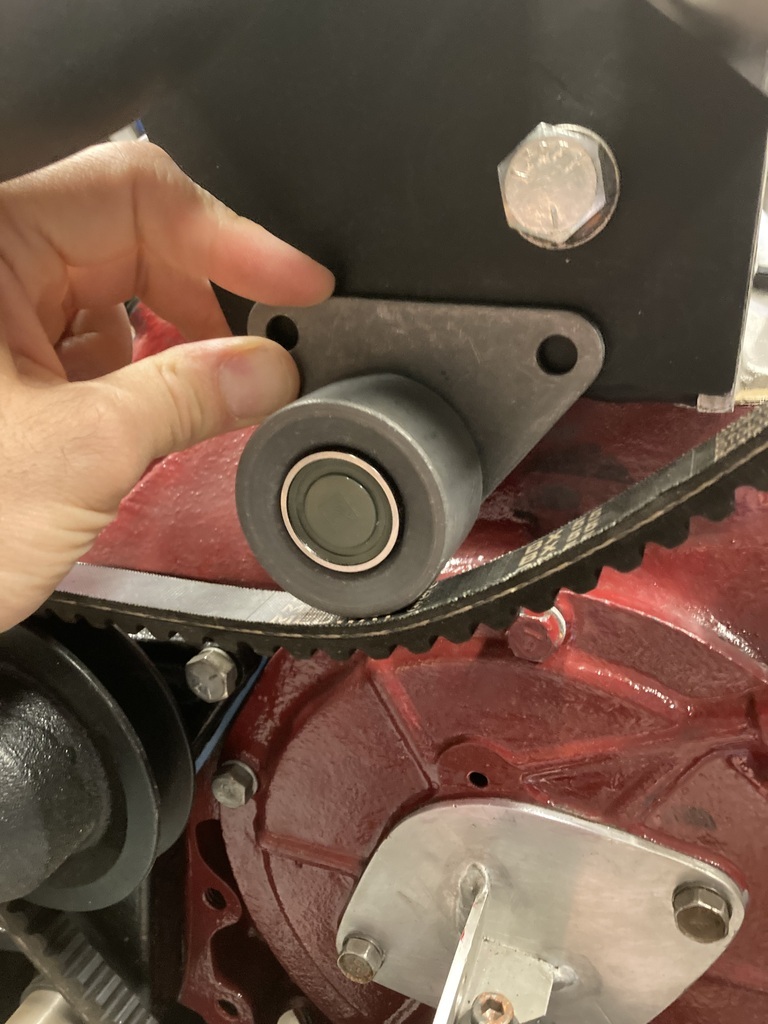
The mounting holes were drilled and tapped straight into the turbo bracket.
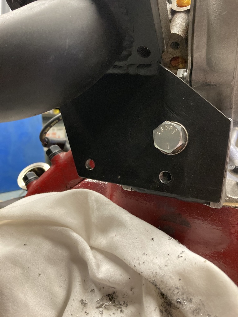
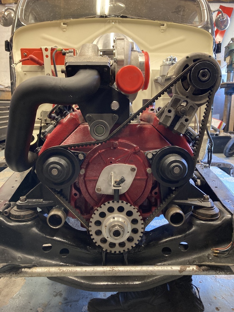
All mounted up.
The long run has been reduced, the turbo clears and the belt is gripping the alternator pulley tighter now as well.
I didn’t even need a longer belt!
Trying to keep the progress going between the bigger jobs a nice filler was fitting the water paraphernalia.
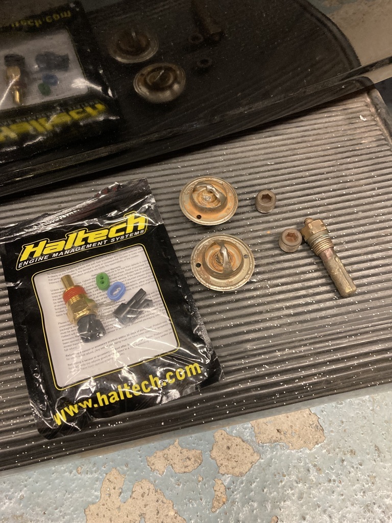
What I had was the water temp gauge sender, blanking plugs for the redundant holes and the thermostats all, again, robbed from the previous engine. A Haltech water temp sender for the engine management was also added to the set.
I discovered a long time ago that Pinto/CVH thermostats were a good replacement for the expensive and very poor quality reproduction Flathead ones.
The only downside is there is no way to hold them.
99% of the time just the top hose clamping around them is enough to hold them in place but they can come loose and spin in the top hose.
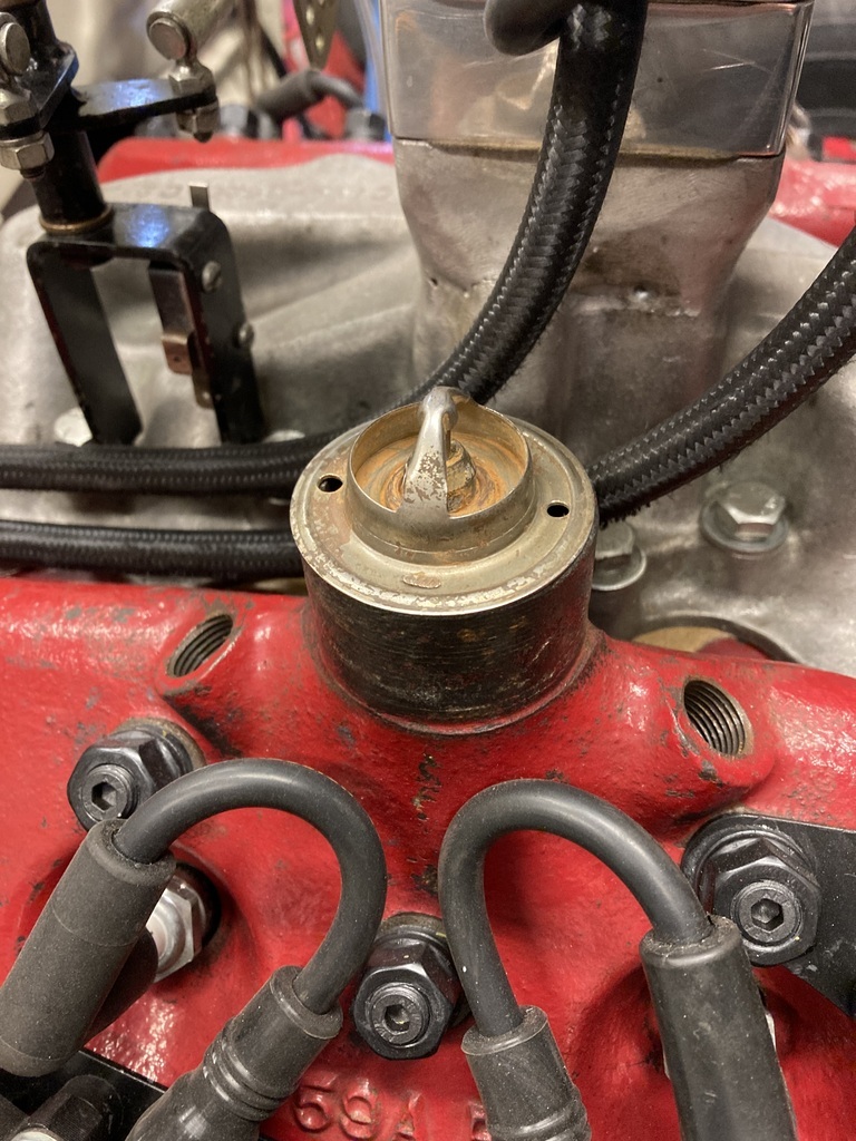
As a belt and braces I wire then in place.
The thermostats are already pre-drilled from being previously wired but the water necks on the heads need drilling for the lock wire.
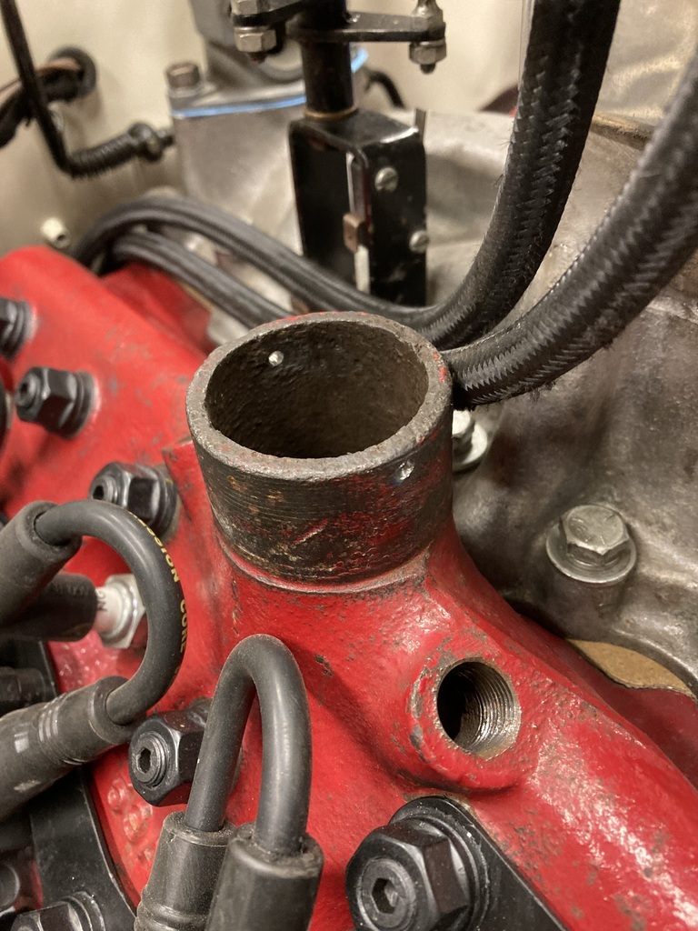
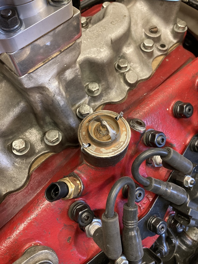
The wired thermostat and the gauge sender and blanking plug in place on the passenger side.
This position is pretty much set as that’s where the wiring is run to.
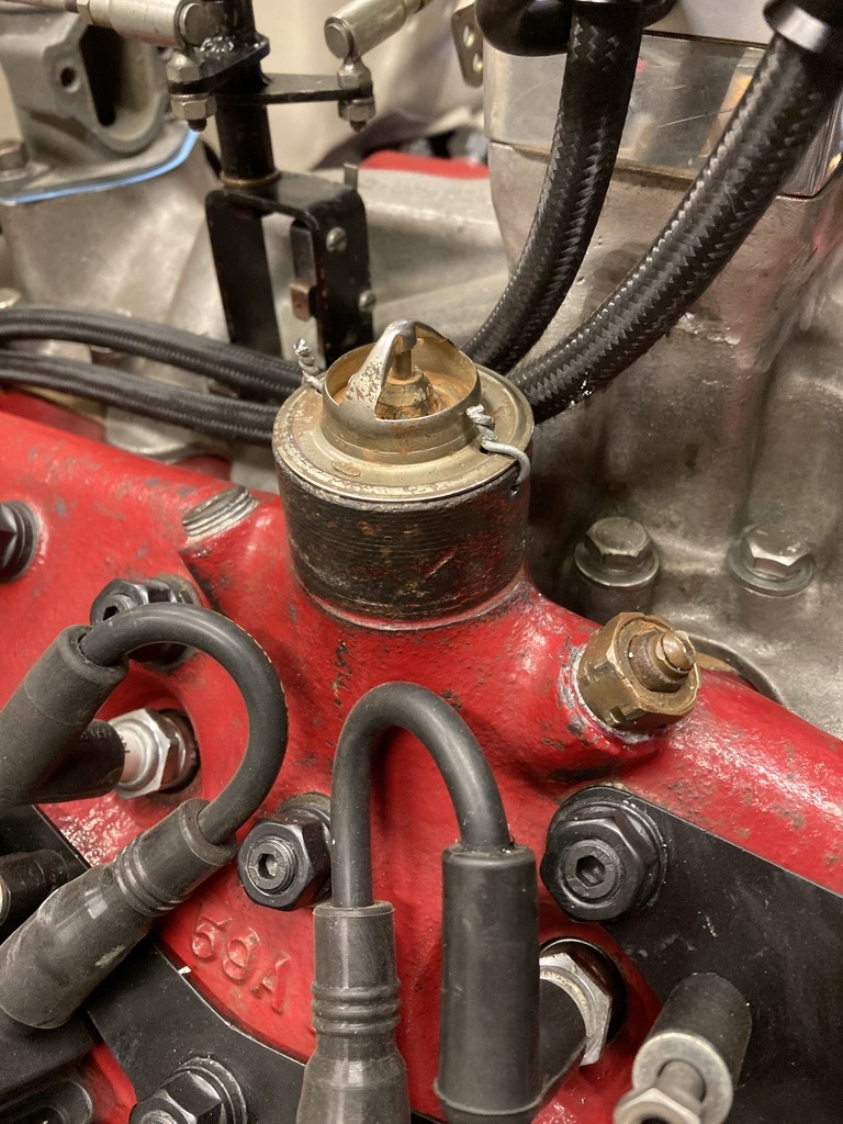
The driver side has the same with the added Haltech sender. This worked out well as most of the senders will end up in the area helping with loom runs.
The turbo needed its clocking finalised so I could start thinking about plumbing pressure lines and drain backs.
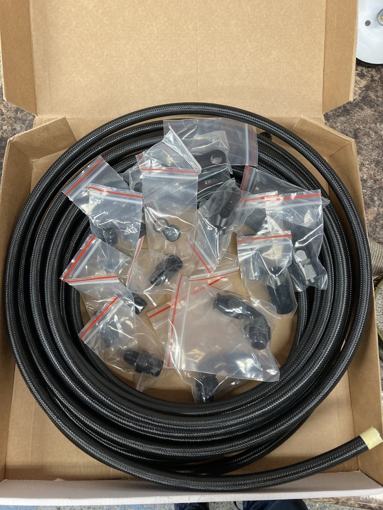
I dug out the “fitting kit” which had come with this £145 Chinese turbo.
Up until now I hadn’t paid much attention.
Here’s what I had from the top…😆
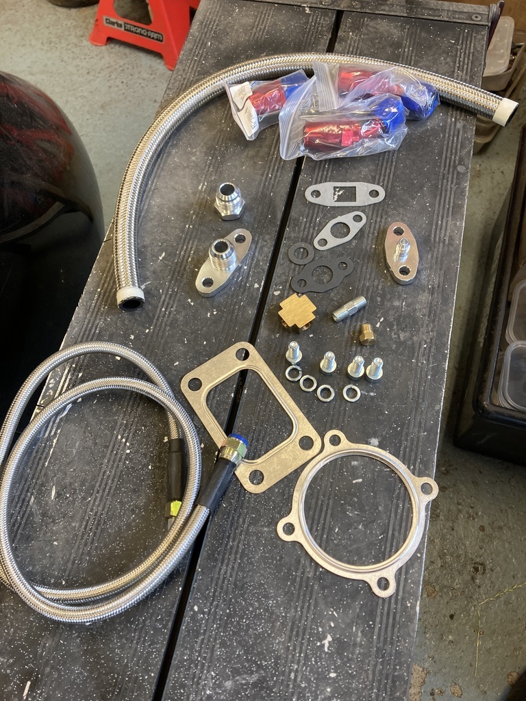
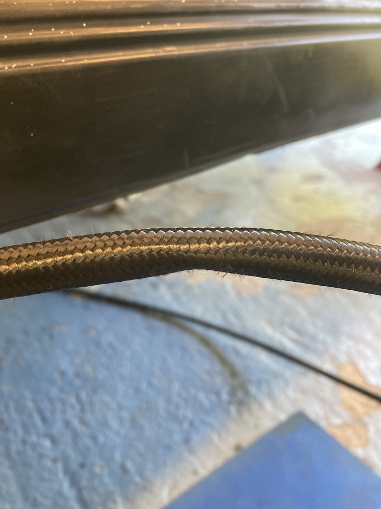
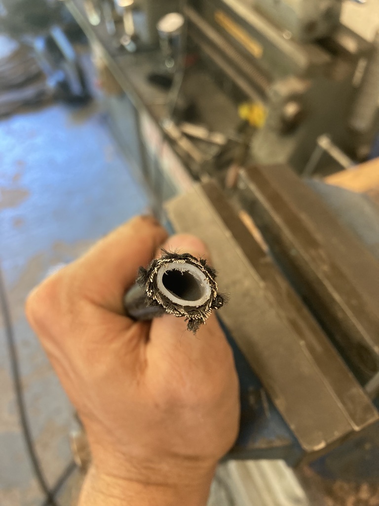
1/2 meter of -10 braided hose - it’s short length making it completely useless.
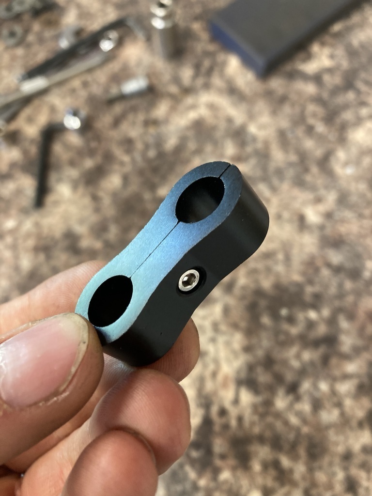
A selection of -10 fittings - I maybe missing something with these but I see no means of them actually clamping a hose.
A random selection of gaskets.
A -10 weld on bung
A drain back adapter and a restricted feed adapter
A 4-way adapter with one male/male adapter and a blanking plug - these items do not mate up with any other items in the kit.
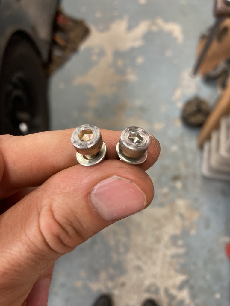
Some fixing bolts
Two steel shim gaskets
And my favourite,
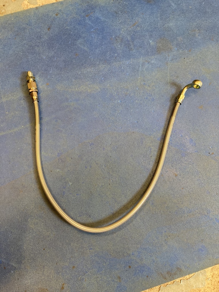
A -4 braided pressure line that, again, doesn’t fit anything in the kit!
So, most of that will be going in the bin!
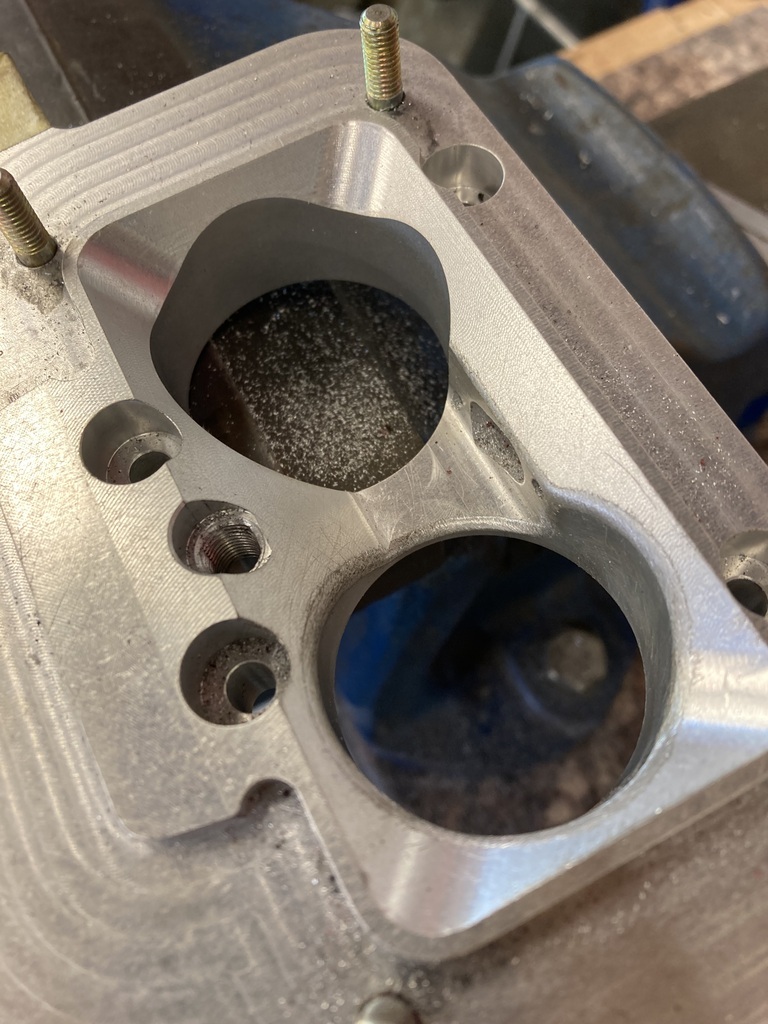
This was identified as the drain back port.
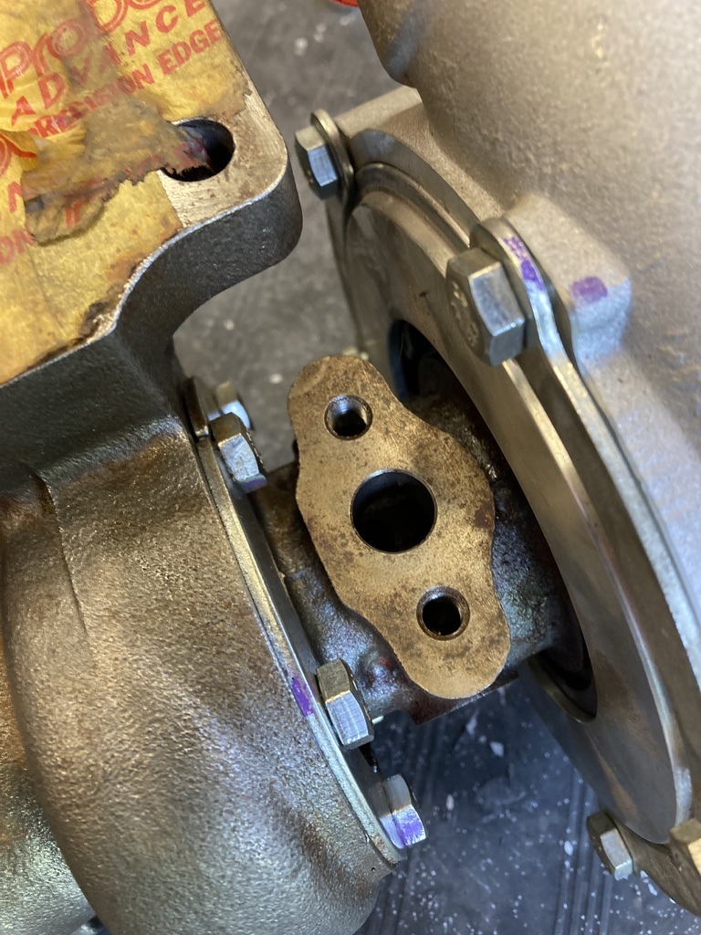
Which the drain back adapter didn’t fit.
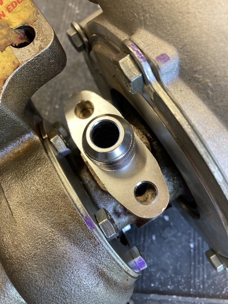
The restricted one fitted perfect it. 🤦♂️
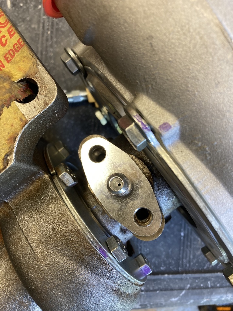
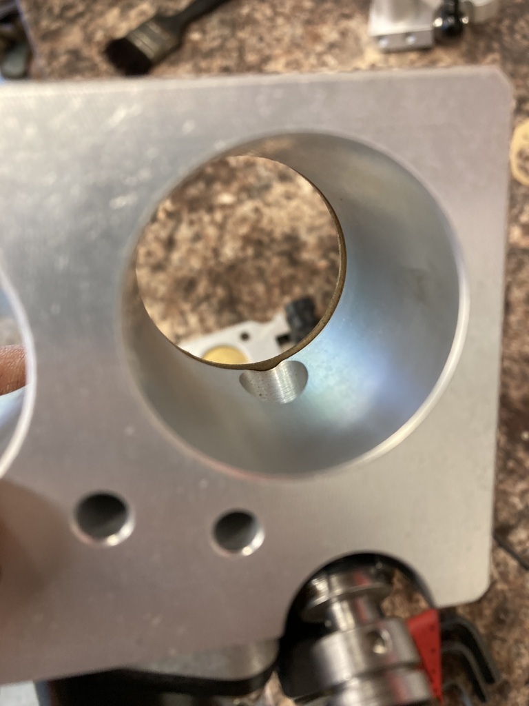
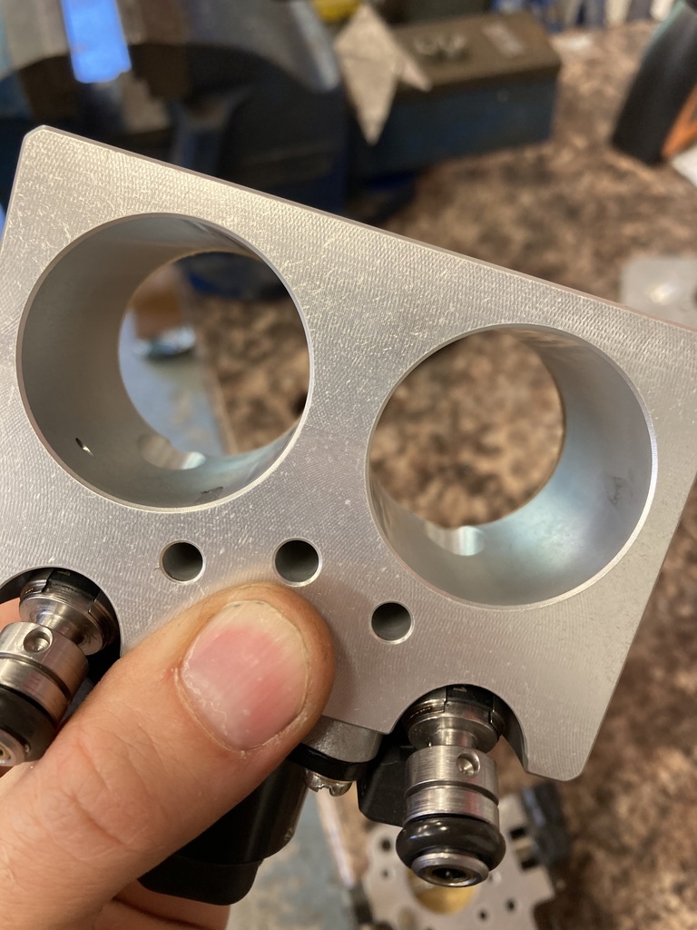
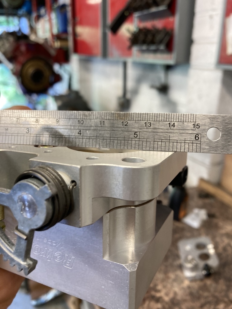
Apart from the mounting holes not lining up the rest of it was fine (kind of) so I slotted the mounting holes to make it fit.
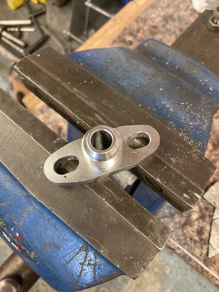
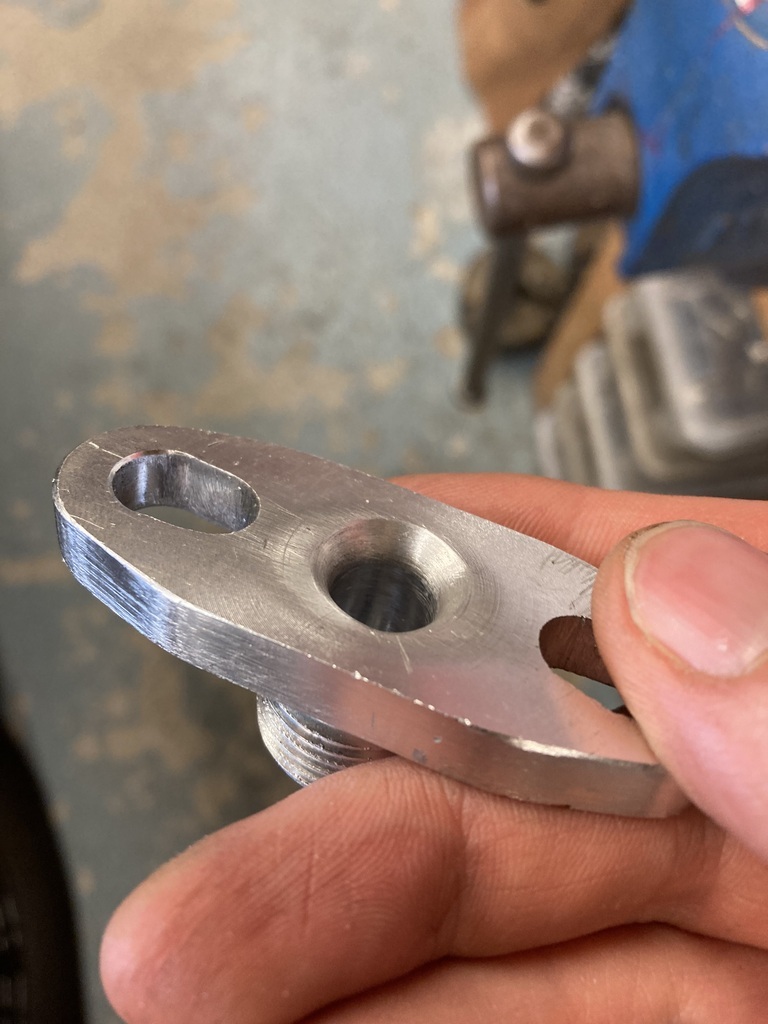
The centre hole was smaller compared to the turbos one so this got a heavy chamfer and then blended to remove any restrictions in the flow of oil.
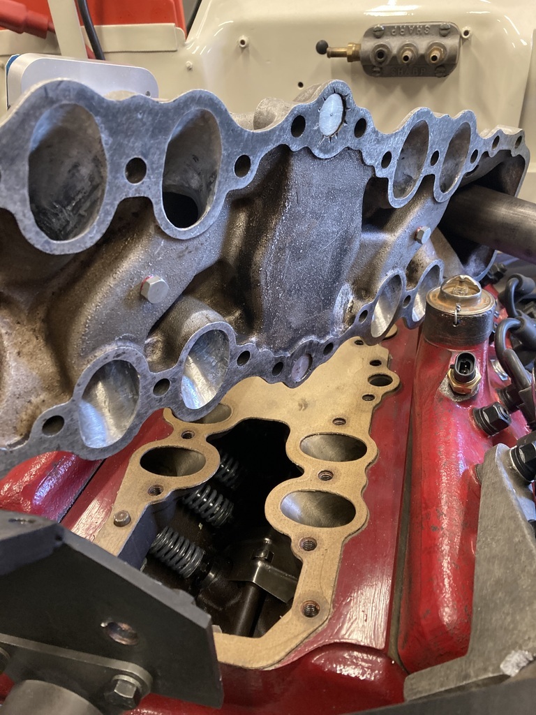
The inlet manifold had been torqued down for while when one night I woke up in a cold sweat.
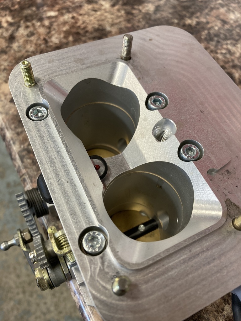
The reason being I didn’t remember blocking up the now disused PCV holes on the underside of the inlet.
The next day I still couldn’t remember so had no choice but to take it back up again.
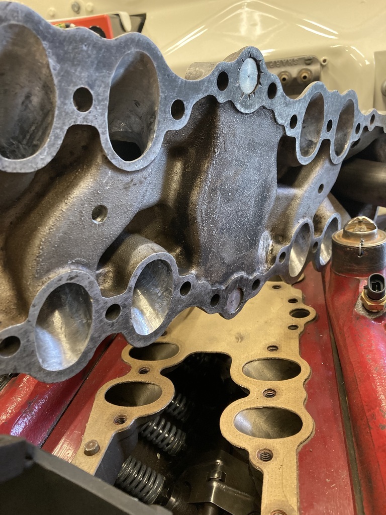
Luckily I did because, yep, they had been left open.
That could have got messy.
