|
|
|
Aug 23, 2023 10:21:57 GMT
|
Slightly frustratingly, I've realised I've made a complete error on the circuit here and my variable capacitor won't work. Here's why: 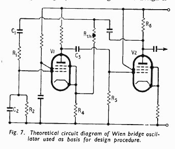 Capacitors C1 and C2 are equal and have to track together for a variable frequency. Note where R1 is, between them. Now look at the layout on my variable capacitor: 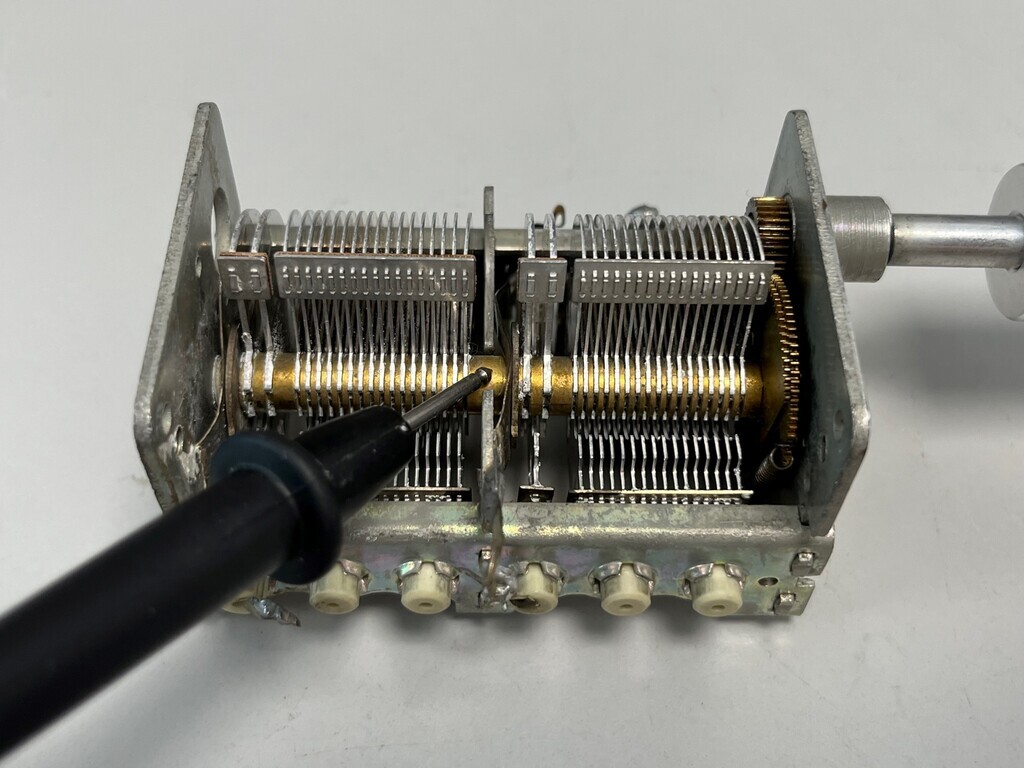 All four segments share a common ground on the shaft, which is connected to the capacitor chassis, which is grounded to earth/0V through the case. I've thought about how I could isolate and/or split it up, but it's all pressed and soldered together so it's not going to be possible. Argh! But I'm sort of glad I spotted it at this point and not further along... So plan B is variable resistors. I've seen it mentioned that normal dual gang carbon pots don't track closely enough for the circuit to work and that precision wirewound ones need to be used. Another issue, which I need to confirm, is that you normally turn a pot clockwise to increade the resistance and that means the frequency will go down. Intuitively, that's backwards on the dial. I've spotted a dual 30k wirewound on eBay which looks like it might come apart and therefore I might be able to reverse the resistors: 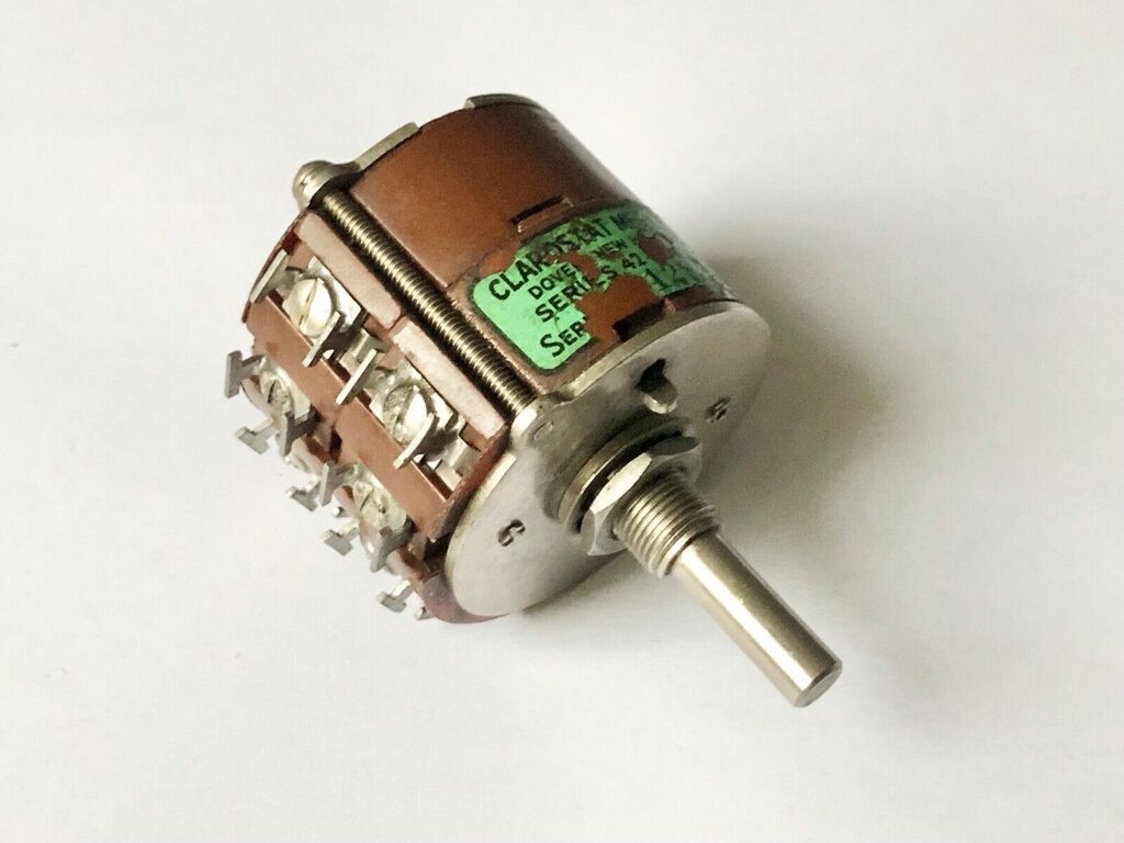 Edit: that should be fine because it looks like it has 3 connections so nothing needs reversing. The only other issue with that is it's linear and I think I need a logarithmic range so that all the variation isn't concentrated at one end. I may need to put a 30k resistor across it in parallel to make it nearly logarithmic. The question is going to be whether the resulting 15k is going to be sufficient resistance to give me a decent low frequency range with realistic capacitor values. I need to do some maths. You can see why solid state made all of this WAY easier. |
| |
Last Edit: Aug 23, 2023 17:38:20 GMT by Jonny69
|
|
|
|
|
|
|
Aug 26, 2023 23:58:18 GMT
|
I did some calcs in a spreadsheet and both 30k and 15k will be fine, so I ordered it up and here it is: 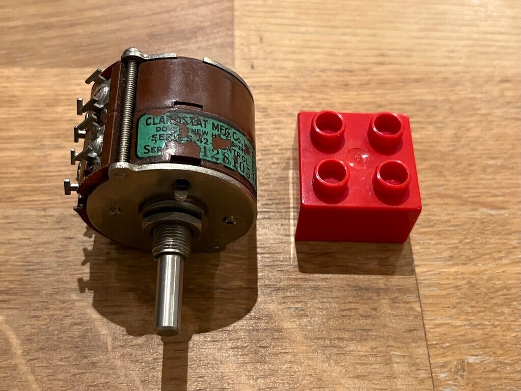 Duplo block for size reference, which is 32mm square I think. This thing isn't small! Both sides seem to track pretty closely, within a couple of percent, which should be good enough for what I need. Curiously, it's got four connections per track. It's got the usual three connections plus what appears to be a centre tap. This had me confused for a while. Pics here mostly for my reference. Shaft turned fully to the left and these two read zero (or near enough): 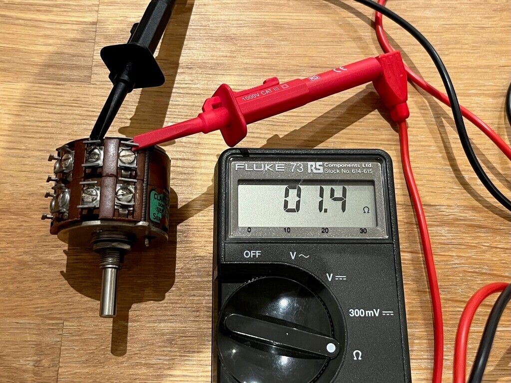 Shaft turned fully to the right and these two read zero: 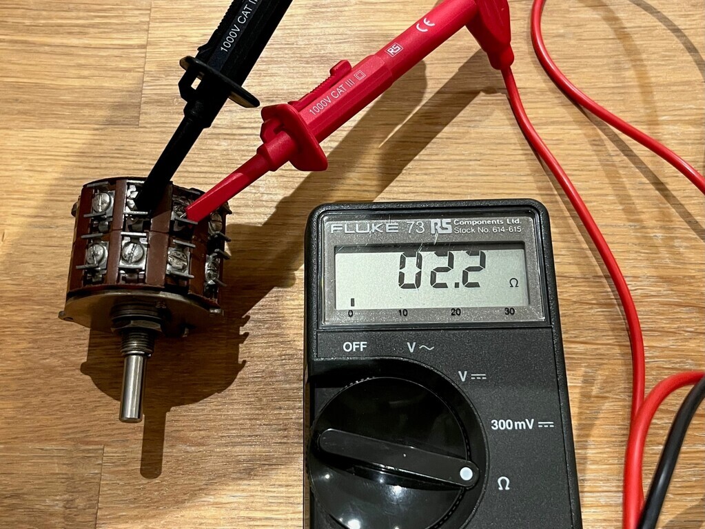 So the tag I've got the red probe attached to above is the wiper. Then the far left hand tag reads 15k at the ends and zero in the middle, which suggests it's a centre tap. Not seen that before: 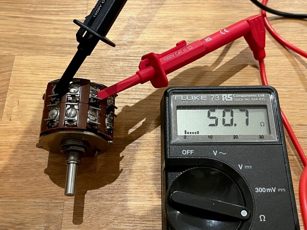 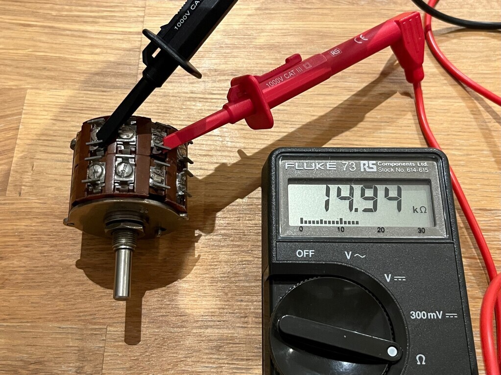 Now to answer the question about whether it's going to act linearly or logarithmically, I did a plot in Excel to see. Divided the resistance range by 10 and plotted it against frequency. Turns out it's going to be logarithmic:  I can't remember where I read if you put a fixed resistor in parallel with a linear potentiometer it acts slightly logarithmically, but when I plotted it on a graph it didn't appear to. Not enough to straighten out the frequency response, anyway. Probably because it's doing a log to base 2 instead of base 10 or something, but either way it's something I should probably remember from GCSE maths log tables. So I probably won't bother and I'll just put up with a logarithmic slope on my dial. |
| |
|
|
jimi
Club Retro Rides Member
Posts: 2,220 
|
|
Aug 27, 2023 10:43:53 GMT
|
Interesting pot, connections on this must be similar?  |
| |
Black is not a colour ! .... Its the absence of colour
|
|
|
|
|
Aug 27, 2023 15:04:33 GMT
|
|
I saw those ones on eBay from that seller with the green monsters! It’s the same model pot, so the connections are the same by the looks of it. Mine doesn’t have that sticker on it.
|
| |
Last Edit: Aug 27, 2023 15:05:16 GMT by Jonny69
|
|
jimi
Club Retro Rides Member
Posts: 2,220 
|
|
Aug 27, 2023 15:16:30 GMT
|
|
I believe Clarostat got bought out by Honeywell who have since stopped production of pots 😞
Funnily enough when I started working it was for an American company called Beckman Instruments, as part of my training I got to work in every department and on every production line, ones of the lines was the Pot line, making precision multi-turn wire wound potentiometers 😀 they made multi-gang ones as well, but I don't recall any with a centre tap like that 🤔
|
| |
Black is not a colour ! .... Its the absence of colour
|
|
|
|
|
Aug 27, 2023 16:05:40 GMT
|
I believe Clarostat got bought out by Honeywell who have since stopped production of pots 😞 That’s pretty much what I gleaned from the internet after a quick look. I’m guessing my one might be 1960s going on the general construction and the waterslide decal. It’s definitely mega high quality, one of those things that feels carefully put together by hand in a way that doesn’t exist any more. The terminal screws are soldered to the terminals after tightening and the long screws that hold the stack together are lacquered to prevent them coming undone. I know from the things that we buy at work, if you want a modern equivalent you have to pay £££££ for quality like this in electronics. £8.50 delivered for a 60 year old NOS component really is a bit of a bargain in comparison and will outlive anything we use at work (and probably/hopefully me). |
| |
Last Edit: Aug 28, 2023 6:25:20 GMT by Jonny69
|
|
jimi
Club Retro Rides Member
Posts: 2,220 
|
|
Aug 27, 2023 17:03:10 GMT
|
|
Yes, it's got the look of the Beckman pots and when I worked on the line (late 60's) they were assembled by hand from quality parts. 😎
|
| |
Black is not a colour ! .... Its the absence of colour
|
|
|
|
|
Oct 30, 2023 22:08:59 GMT
|
Not had much time to spend on this lately. Finally got a few minutes to recap and check my maths. I’m going to breadboard the Wireless World worked example to start with so I can play with it, plus there’s a few things I don’t completely understand and I’ll be able to tinker, then modify it from there by swapping the components in the timing circuit from the fixed 50hz to my variable frequency. There’s something else I want to try too. The original worked example used an EF86 pentode (usually used as an audio amplifier) and an EF91 sharp cutoff pentode (used in old TVs). They gave ways to select the components to suit any pentode, but they didn’t say why they used an EF91 and not just two EF86s. There’s nothing wrong with the EF91, I’m just trying to get my head around the differences between the different pentodes. I’ve got some pentodes below which should be a direct swap: Russian EF86 on the left, EF91, the EF80 superseded the EF91, and then the EF184 superseded the EF80. I think they basically worked the same, but were improved so they could be driven harder as televisions evolved.  |
| |
|
|
|
|
|
|
|
This is what I'm going to use to breadboard/prototype the Wien bridge circuit and experiment with the different pentodes:  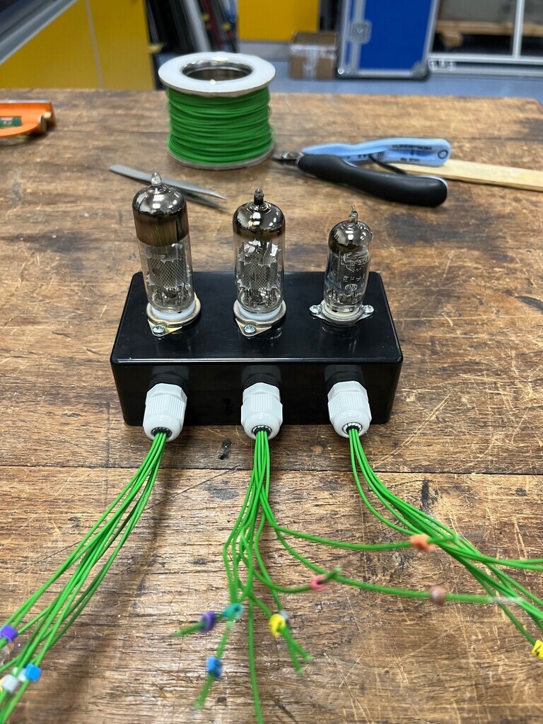 Knocked this up at lunchtime. It's got two 9-pin B9A bases and one 7-pin B7G base. Got all the wires numbered up. It'll allow me to easily swap wires around to suit the different pin-outs of the pentodes. |
| |
|
|
jimi
Club Retro Rides Member
Posts: 2,220 
|
|
|
|
They look like RS wire markers, used them a lot offshore, colours make them easy to identify if the numbers have gone, used to know the number/colour off by heart  |
| |
Last Edit: Nov 2, 2023 15:12:43 GMT by jimi
Black is not a colour ! .... Its the absence of colour
|
|
|
|
|
|
|
|
|
They look like RS wire markers, used them a lot offshore, colours make them easy to identify if the numbers have gone, used to know the number/colour off by heart  Good spot, almost certainly old RS stock! |
| |
|
|
|
|
|
|
|
Much of this has been ticking away in the background. I've been thinking how I might mount up the V2 of the amplifier and I'd quite like to have it on a PCB this time. I haven't come across a PCB for the Mullard or BBC designs with the EF86 pentode input stages (like I built), but there are a number of boards available with an ECC83 dual triode as the input stage. So a 3-valve design for the stereo pair. I actually have a Tubelab SSE board which is a 3-valve design with the bigger EL34 output pentode for about a 10W output, but when I looked at the transformers I decided it was prohibitively expensive. I'd be looking at minimum £450+ for transformers and I can't justify that. I looked at modifying the components on the Tubelab SSE board to suit the smaller EL84 output pentode. It would work, but one of the disadvantages is the layout on the board. Because it's designed for the bigger valves, it's a bit spread out. And I'd have to mount the valves off the board to convert from an the EL34's octal base to a B9A base for the EL84. The advantage though is it's probably got a good layout for noise, cooling etc and it's gold plated. I then had a look at the Chinese eBay offerings and decided to have a closer look at one since it was about £10 delivered. So, as expected, it's not the same as the one described. The board is actually nicer looking in purple instead of yellow. The circuit is very slightly different and when I traced it back over the circuit diagram I found a couple of improvements that I would have made. So that's a good thing and all I have to do is check and tweak a couple of component values to suit how I want it. 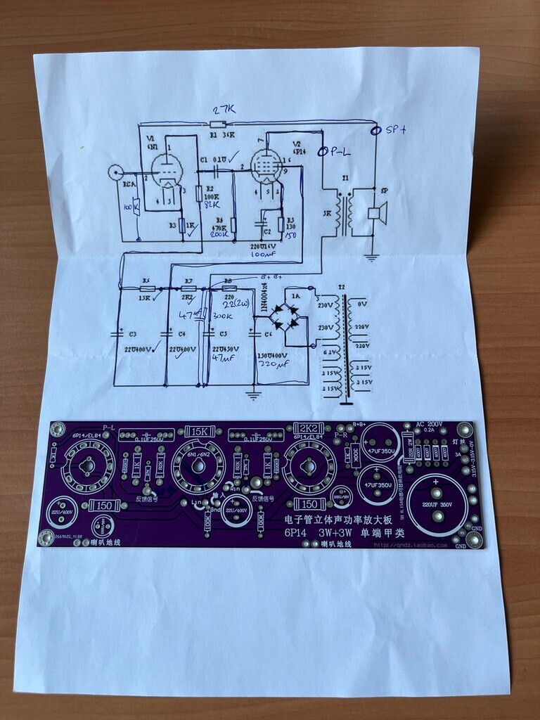 Board in the eBay description for comparison: 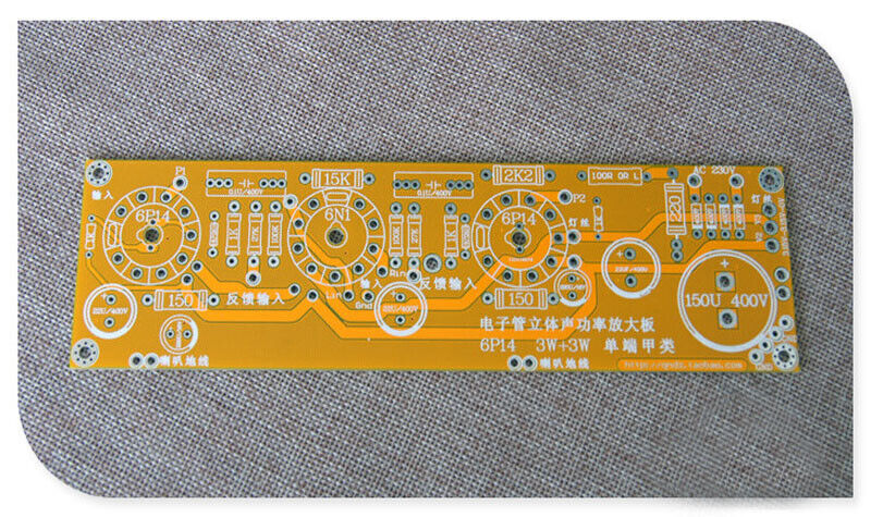 Nixie clock is on hold for the moment. I've got a backlog of projects and a couple of things ought to come first. They were the right tubes at the right price and take a bit of scouring and watching on eBay, so I snapped them up at the time ready for use later on. |
| |
|
|
|
|
|
Nov 23, 2023 20:01:10 GMT
|
I’ve begun. Got some time in lieu to use up so I’ve taken the opportunity to put some time into this. I wanted to have a play with the pentodes first and I was going to just bodge some wires onto the power supply to get it running. However, since I’ve got a bit of time I decided to plumb the PSU into the oscillator case properly, through the IEC socket, switched and earthed. Advantage being when it’s in an earthed case it makes it a lot harder for me to accidentally touch something and make me go bang. I added a 300k discharge resistor from the HT to earth, which brings the voltage down to a safe level after just a few minutes when switched off. Then I bodged on the wires I needed like this and stuck it in the case, which is all much safererer:  So after lots of voltmeter poking to make sure I wouldn’t accidentally die, I was confident to stick some components on the breadboard. I started with an EF80 (RF pentode) and used the EF80 part of this circuit, which is basically identical to what you’d use with an EF86 audio pentode: joefreeman.weebly.com/uploads/1/3/7/7/13770951/ef80-el84_amp_iv.pdf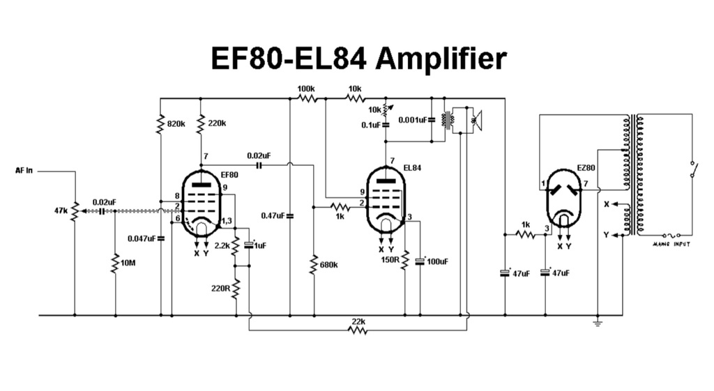 I got the binfind function generator out and set it to 1khz and 100mv rms and then flicked the power on. Nothing went bang and this is what I got: 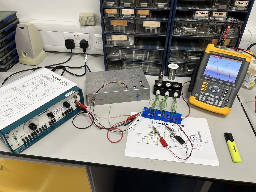 So with an output of 21V, give or take some component tolerances, that’s a gain of around 200. Seems to look fairly undistorted up to around 45V output and it looks like it starts to clip at around 50V. Couple of things I want to try tomorrow before I switch it to the EF86: 1) try it at different frequencies and see how flat the response is. 2) add a negative feedback loop and look at the ratios. See if there’s a relationship like there is with modern op amps. 3) swap the cathode resistor for a pot and play with the bias point. I know a lot of this is in old literature but it’s not explained well. Sometimes the best way to learn is to just roll your sleeves up and get your hands dirty. |
| |
|
|
|
|
|
Nov 24, 2023 21:50:21 GMT
|
Added a simple negative feedback loop from the output directly to the input with a resistor inline:  I didn’t have any resistors in convenient decade values, so I had to go for what I had closest in multiples of 10. So that was 8.2M, 820k, 82k and 8.2k. They all worked as expected and attenuated the output voltage. I’ve got a nice list of numbers to play with now. Now I know the voltage gain in a generic circuit is roughly this for the following valves: EF184 RF pentode 285, EF80 RF pentode 211, EF91 sharp cut-off pentode 218, EF86 AF pentode 149. The gain on the AF pentodes are probably lower to make them less microphonic. Audio triodes have a gain of about 70 I think, and they're said to be better in guitar amps because they're less microphonic than pentodes. Then I did some frequency sweeps to look at the frequency response. Did it on all three valves and plotted them in Excel with the output voltages normalised: 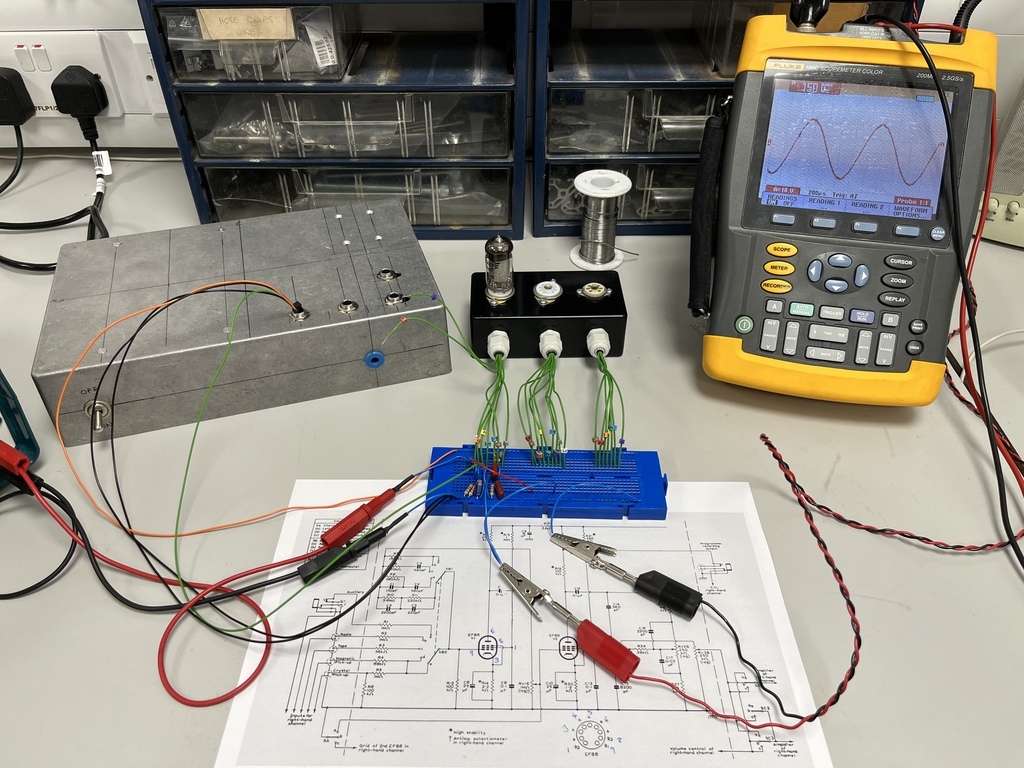 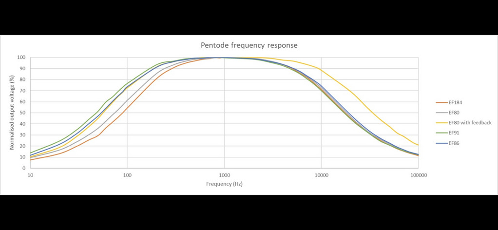 This was where I got a surprise. I was expecting them to have a pretty much flat response, but it’s not so. The bit I don’t fully understand yet is how the response gets flattened in an audio amplifier. I put my negative feedback loop from the output to the input. You can also run the feedback partway into the cathode, which I guess changes the bias with respect to the frequency response. I think it might be this. More experimenting needed… The other interesting thing was almost no difference in response between the RF, sharp cut-off and AF pentodes. I was expecting them to be different. Final interesting thing was what happens to the lower response when you change the cathode capacitor: 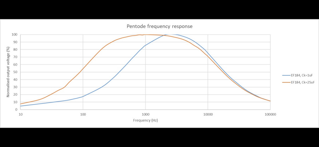 Loads to take in there. I’ve learned a lot. |
| |
|
|
|
|
|
Nov 27, 2023 18:04:33 GMT
|
More lunchtime experimenting. I swapped the feedback to cathode feedback:  On the graph are normalised outputs for EF80 with no feedback, EF80 with direct feedback loop and EF80 with two levels of cathode feedback. That extends the frequency response at the top end, but obviously at the expense of a significantly reduced output voltage. Audio amplifiers tend to have a feedback loop which is a resistor and capacitor in parallel like this: 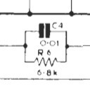 I'm guessing the capacitor lets more through at higher frequencies and thus flattens out the response at the bottom end. Then the rest is filled in with the inductance from the output transformer. I'm sort of guessing here again. Anyway, that's all been really interesting. I've been breadboarding* the Wien bridge oscillator as per the worked example and got it working. I didn't use a thermistor to stabilise the circuit, just a fixed value resistor, so it modulates a bit but it basically works.   I didn't use particularly high tolerance components but it seems to hold a fairly accurate 50hz. The output modulates between about 14V and 19V due to the lack of thermistor. I need to stick a scope on the circuit in a couple of places to check it over and I think once I've done that it'll be ready to play with. *not very neat breadboarding  |
| |
|
|
jimi
Club Retro Rides Member
Posts: 2,220 
|
|
|
|
Neat and breadboard aren't normally seen together in the same sentence  |
| |
Black is not a colour ! .... Its the absence of colour
|
|
|
|
|
Nov 29, 2023 21:39:14 GMT
|
|
Lol! I wanted to check the 50hz mains hum wasn’t influencing the 50hz timing circuit. It is, and it’s causing the modulating. When I changed the timing resistors to around 110-120hz the modulating went away. Swapping the heater circuit to DC ought to fix that I would have thought. I could see it quite clearly when I was recording the frequency response of the pentodes and I’m using the same PSU, so that’s how I know where it’s coming from.
|
| |
|
|
|
|
|
|
|
I got rich to merge the amps and synth threads into one since there was starting to be a lot of overlap and I was losing track of what was in which thread. Thanks for that  When I get 5 I'll edit the first post to include the synth stuff. ---------------------------------------------------------------- I got the circuit working with a thermistor: 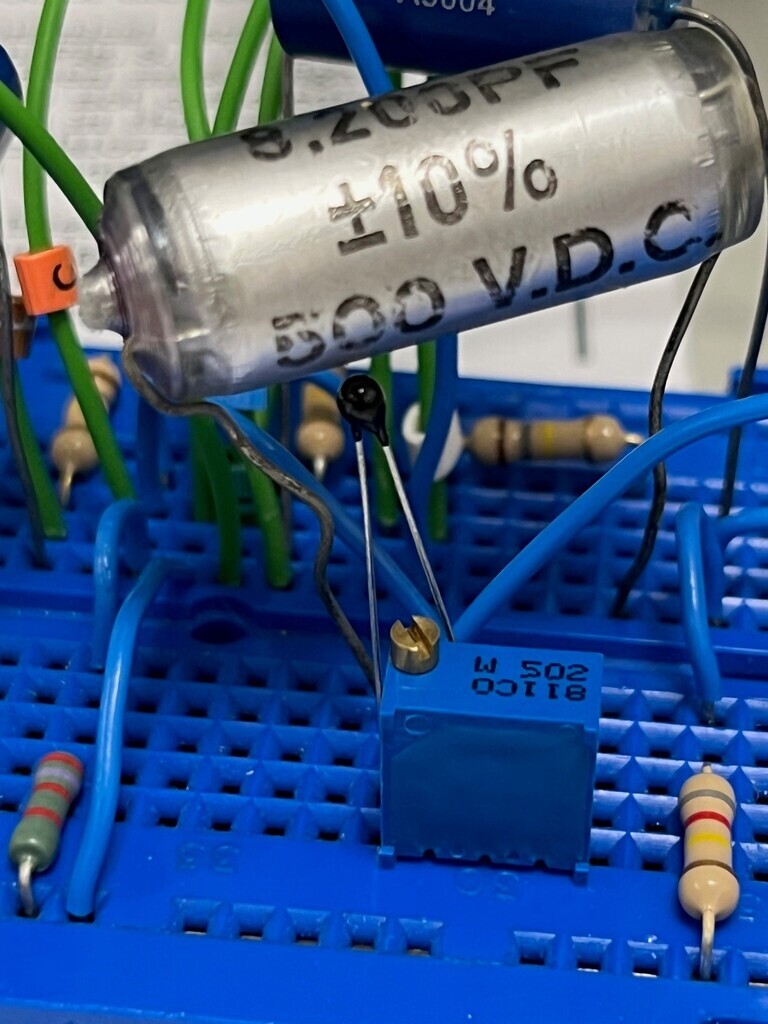 So it's not exactly functioning as per the original design said it would. Obviously I'm not using the original thermistor, as that type is long discontinued. That means the rate of change of resistance is probably not exactly as per the original one would have been. However, my circuit does seem to want a higher value resistance than the original circuit said it would want. That is probably a combination of tube age / variation from OEM spec and maybe the fact that I'm using 30-40 year old capacitors which might have drifted out of spec. Either way, it still works with a bit of tweaking so I'm happy. The way I built it with the potentiometer, it needed around 5.87k to hold 16V output. Increasing the output to clipping (~30V) meant increasing the resistance to 5.92k (so not very much of a change). Reducing the resistance until the oscillations stop meant reducing it to 5.84k (again, not very much of a change). So it was very sensitive to the resistance and very sensitive to changes. With the thermistor inserted, I needed a resistor in series to increase the overall resistance anyway, so I used a 5k pot. Starting at 1k, I increased the resistance until I got the original 22V output. It is nowhere near as sensitive now and much bigger changes to the potentiometer make almost no difference because the thermistor compensates. Now I'm interested to see what happens to the output when the timing circuit is altered. |
| |
Last Edit: Dec 6, 2023 17:33:15 GMT by Jonny69
|
|
|
|
|
|
|
This arrived. Nixie clock bit of this thread progresses…  |
| |
|
|
jimi
Club Retro Rides Member
Posts: 2,220 
|
|
|
|
Impressive kit 👍  |
| |
Black is not a colour ! .... Its the absence of colour
|
|
|
|


