|
|
|
Jan 10, 2022 16:14:32 GMT
|
This thread is now both my amplifiers and synthesizer threads all in one thread. There was a lot of crossover between the two and it was getting difficult to keep track of what was in which thread. Here it all is in one place and hopefully the links below work ok. Contents: 1) Maplin 150W MOSFET amp rebuild starts in post 22) Maplin Millennium valve amp rebuild starts here3) Mullard two-valve pre-amplifier build starts here (added a Soviet luminophore power light on page 8) 4) 1000V variable power supply starts here5) Mullard 3-3 BBC Am8/2 3W stereo class A valve amp starts here (working properly on page 7, probably working better on page 8) 6) Playing with Soviet luminophore lamps starts here and used one for the pre-amp indicator here7) Magic Eye VU meter starts here (working on page 11) 8) Playing with Soviet VFD number tubes here and the thyratrons here9) Synth project officially starts here: Original opening post. VCO hooked up to something and working here10) Wireless world valve oscillator articles: forum.retro-rides.org/post/2764425/thread11) Salvaged test kit on page 12 here
12) Look Mum No Computer modular synth modules start here13) Testing better quality transformers for the 3W valve amp page 13 here (rebuild coming later) 14) Valve oscillator design and build starts here: forum.retro-rides.org/post/2785323/thread15) Bought a haul of valves to play with: forum.retro-rides.org/post/2785323/thread16) 9) Some kind of Nixie clock display thing one day Found some nixies in good condition at a sensible price here and here
17) A test box for breadboarding valves: forum.retro-rides.org/post/2801762/thread18) Audio and RF pentode testing and comparison starts here19) Prototyping the valve oscillator at the bottom of this post and working with variable frequency on the bench here20) Universal Nixie Tube Clock Kit build starts here |
| |
Last Edit: Dec 11, 2023 17:33:12 GMT by Jonny69
|
|
|
|
|
|
|
Jan 10, 2022 16:19:03 GMT
|
Maplin 150W MOSFET amp: Back in the 90s when I was a teenager, I used to do house parties and a bit of DJing. It kind of led to my stereo growing into a pretty big soundsystem and I used to do house and hardcore events in pubs and halls. It was all home made kit except for my 12" flight case speakers. Something I built a number of, were these 150W MOSFET amplifiers from Maplin. They were pretty bombproof and would survive no matter who was at the mixer. The one here is the sole survivor, which I built when I was about 15. I can't remember exactly how many of these I built, but it must have been 6-7. I know I blew up the first one I built, because I remember connecting the power supply backwards during testing and all the caps exploded. There's the stereo pair I'm going to talk about here. There was a pair that I bridged to make a 400W sub amp, using an audio-grade op-amp to invert the signal. Those ones eventually blew. Then, there's a very crusty 47K dual potentiometer in my electronics box which is evidence of another stereo pair which had a volume control. I don't remember that one or what happened to it. I built it in two cases to keep the noise down - one for the amplifiers and one for the power supply: 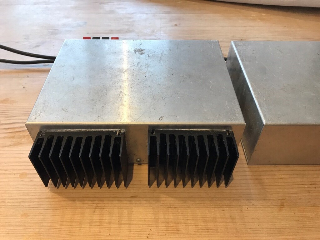 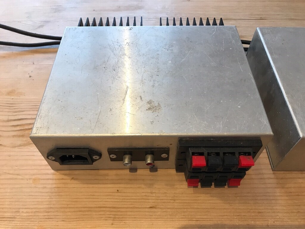 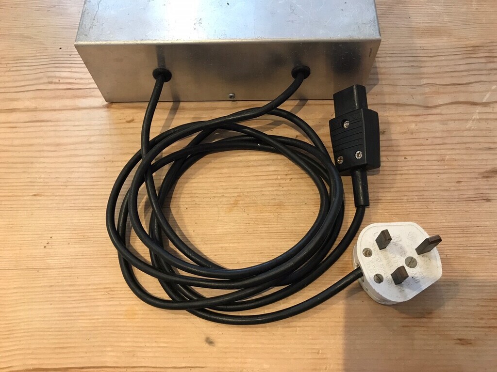 There was no volume control because they were fed directly from my mixer which controlled the individual levels. There were two speaker outputs because these could drive 4 Ohms and I could hook up two sets of 8 Ohm speakers in parallel. +55V/OV/-55V DC was taken from the PSU to the amps by the kettle plug; not ideal, but I couldn't think of a better way to do it at the time and still be able to separate the boxes for easy transport. Everything was sourced from the Forest Hill Maplin in SE London, which was on the bus route on the way home from school. It was an EXTREMELY rare thing to be near a physical, actual Maplin shop back then and this one was complete with all their books on the shelves, wooden hatch at the back where you asked for components and all the staff were electronics experts (well, to me, anyway). No silly cheap plastic radio controlled cars, no rubbish plastic 100000W PEAK MAX PMPO speakers, just the nerdy electronics stuff. So bear in mind that I made these around 1993 and as far as I can remember I haven't opened them since I built them. This is what I found inside: 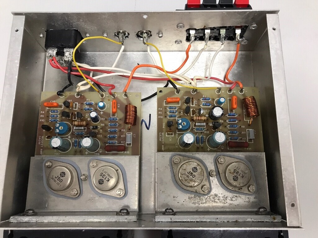 A little bit messier on the wiring than I expected, but I was only 15. Looks like cutting holes wasn't my strong point: 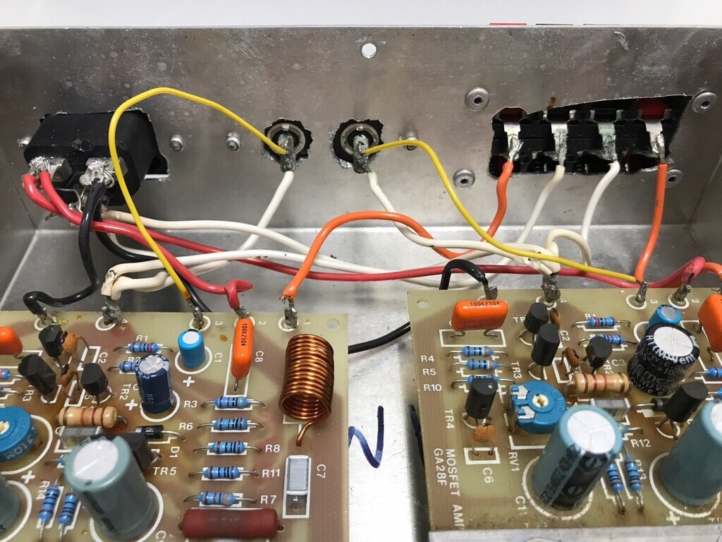 I say that, but I didn't have a small battery drill or sharp drills like I do now. I'd have done this with dad's Black and Decker power drill, chain-drilling with whatever drills he had knocking around and a hacksaw. I don't remember having a file. That was my own pop rivet gun. The amps I noticed are not the same length or the same height. I assumed this was more of my poor drilling, but both the amps are slightly different. This might have been because I blew the first one up and had to get a replacement, so they might be from different batches. Have a look at the size of the heatsink plates under the MOSFETS and they're slightly different too: 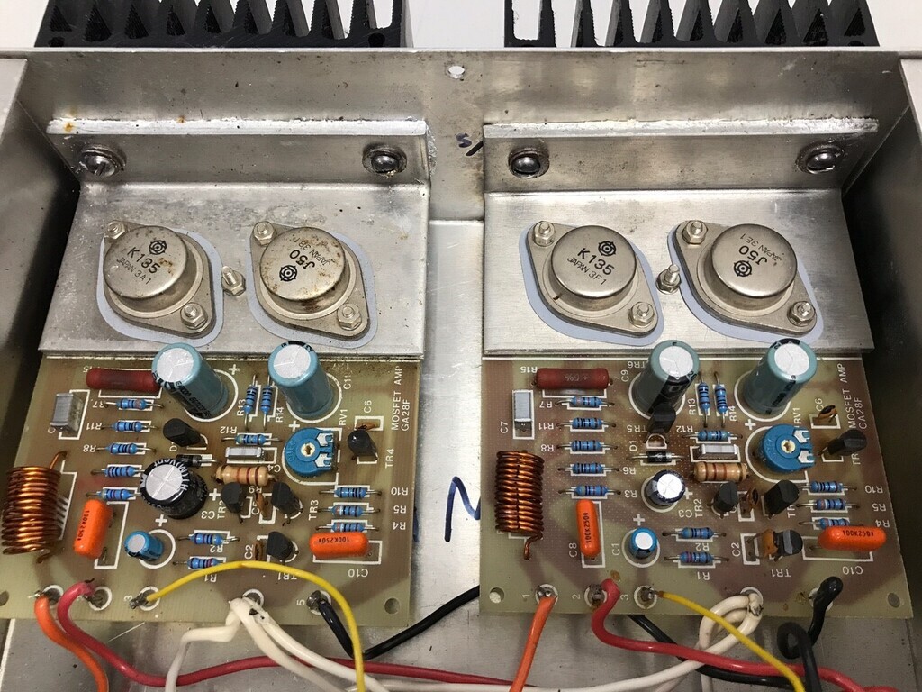 I know I etched a number of circuit boards for the PSUs using photoreactive PCB sheets in a new UV light box my school had bought. I guess I would have printed the circuits onto OHP acetate, slung it into the light box for a couple of minutes, into developer fluid, then in to the etch tank. God knows what chemicals we used with no gloves or safety specs. I was hoping to find one of these in the PSU box, but it's unfortunately just tag-wired together. I am slightly disappointed because I know I made at least two of these and it would have been great to see them again. The plan. Rebuild. Slightly safer, slightly different layout and with a volume control. Re-use the cases but tidy them up a bit first. One amp module is loose (probably from being dropped and bashed about) so I'm going to come up with a slightly better mounting system. I was thinking of swapping the PSU connections to DIN rail power distribution blocks, but I think it might not be worth it. I've got some old-school tag boards which might be more fitting for the build: 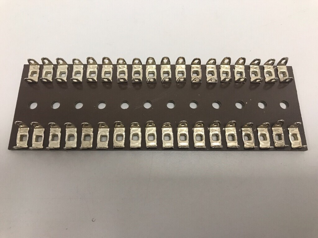 On top of that, they need some new feet which I might 3D print. Some fuses and better earthing might be nice. After that I'll fire them back up and re-set the bias and quiescent current (which I never actually did properly back in the day). Then they're going back into use in the living room with a nice retro knob on the volume control. References. Pretty sure this is the 90s Maplin Magazine article which accompanied the kits: bhiab.se/data/files/03667481__skanna0060.pdfThis is the earlier iteration with the lower output and resistor inside the output inductor: www.muzines.co.uk/articles/mosfet-amplifier/2651 |
| |
Last Edit: Dec 11, 2023 17:17:30 GMT by Jonny69
|
|
autojumbled
Club Retro Rides Member
Posts: 226
Club RR Member Number: 106
|
|
Jan 10, 2022 16:31:54 GMT
|
|
very nostalgic!
During 2020 when we were all at a loss on what to do with ourselves I thought about digging out a box of late 90's Everyday Practical Electronics magazines to have a crack at a project but to my horror realised that they've been chucked....
Most of the stuff in those was probably past my skill level anyway but they also had interesting reads.
Show us the rebuild of the amp when it starts!
|
| |
|
|
squonk
Part of things
 
Posts: 864
|
|
Jan 10, 2022 23:26:11 GMT
|
|
I've got one of those in a box in the loft somewhere, brand new and never used!!
|
| |
2004 Chevrolet Avalanche Z71
2005 Mercedes CLK320 Cabriolet
1996 Mercedes C180 Elegance Auto Saloon
1996 Rover 620Ti (Dead fuel pump)
1992 Toyota HiLux Surf
1987 Range Rover Vogue (Rusty)
1992 Range Rover Vogue SE (More Rusty)
2006 Chrysler Grand Voyager
2008 Corsa 1.4 Design
|
|
|
|
|
Jan 11, 2022 10:24:10 GMT
|
During 2020 when we were all at a loss on what to do with ourselves I thought about digging out a box of late 90's Everyday Practical Electronics magazines to have a crack at a project but to my horror realised that they've been chucked.... Most of the stuff in those was probably past my skill level anyway but they also had interesting reads. Argh, No! I pretty much grew up reading those in the library. I remember a number of articles from the mid 90s that I wanted to build but were way outside my capability. There was the Theremin, TENS machine (ok, ok, I admit it, I just wanted to electrocute people), various audio pre-amps that I tried to modify to become analogue crossovers, and a (Mullard?) valve amp. No way the valve amp was going to ever get built because there was no way of getting suitable transformers, so imagine my glee when Maplin launched the Millennium Valve Amp in 1995/1996 which was almost identical the EPE one. I'm going to do a future thread on that one because that needs a check-over and rebuild as well. |
| |
|
|
squonk
Part of things
 
Posts: 864
|
|
Jan 11, 2022 10:34:50 GMT
|
and a (Mullard?) valve amp. No way the valve amp was going to ever get built because there was no way of getting suitable transformers, so imagine my glee when Maplin launched the Millennium Valve Amp in 1995/1996 which was almost identical the EPE one. I'm going to do a future thread on that one because that needs a check-over and rebuild as well. I've got a Leak TL12 monoblock valve amp that has bulging caps that needs rebuilding. Could do with a second one to make a stereo pair but they are getting a bit epensive now. |
| |
2004 Chevrolet Avalanche Z71
2005 Mercedes CLK320 Cabriolet
1996 Mercedes C180 Elegance Auto Saloon
1996 Rover 620Ti (Dead fuel pump)
1992 Toyota HiLux Surf
1987 Range Rover Vogue (Rusty)
1992 Range Rover Vogue SE (More Rusty)
2006 Chrysler Grand Voyager
2008 Corsa 1.4 Design
|
|
|
|
|
Jan 11, 2022 11:44:14 GMT
|
I've got a Leak TL12 monoblock valve amp that has bulging caps that needs rebuilding. Could do with a second one to make a stereo pair but they are getting a bit epensive now. Nice! That looks like it'll be an expensive rebuild. If it's the oil-impregnated paper-dielectric caps that need replacing, it looks like it's those that contribute to its sound quality and modern electrolytic caps won't sound the same. Plus KT66 valves are difficult to get hold of these days. Mine at least uses modern components and EL34 valves, so it's relatively easy to get parts for. Only issue on mine, looking back on some old emails, is that the power transformer (which I replaced) was buzzing and started blowing the fuse. I was talking to a guy over email about it about 10 years ago and realised I was actually talking to Mike Holmes, the original designer. He said it was common for this to happen if built to Maplin's specs and to uprate the fuse, insulate the transformer and consider bleeding some resin into the transformer core to halt the vibrating. His site is still up but no idea if he's still around or even still alive. He must be getting on a bit if he is. I might drop him a line. Edit: he posts as Mike H on audio-talk.co.uk forums, still around as of Jan 2022. |
| |
Last Edit: Jan 25, 2022 16:54:30 GMT by Jonny69
|
|
|
|
|
Jan 11, 2022 12:49:02 GMT
|
Argh, No! I pretty much grew up reading those in the library. I remember a number of articles from the mid 90s that I wanted to build but were way outside my capability. There was the Theremin, TENS machine (ok, ok, I admit it, I just wanted to electrocute people)... I built an EPE TENs unit, after my then GF was complaining about some ache or other. It worked quite well, though of course, she was afraid of using it, so I did most of the initial testing!  Nowadays, you can buy them on E-bay for a tenner or so. |
| |
|
|
MiataMark
Club Retro Rides Member
Posts: 2,971
Club RR Member Number: 29
|
|
Jan 11, 2022 14:34:48 GMT
|
|
I've got a John Lindsay Hood derived 75W stereo power amp in the loft, no idea if it still works. Not built by me and uses a standard transformer that isn't really up to the job, but have a toroidal from a kit. Used to use it with a NAD3020 as a pre-amp. Still have the NAD but a channel has blown, need to rebuild it really.
I miss Maplins, and the catalogue.
|
| |
1990 Mazda MX-52012 BMW 118i (170bhp) - white appliance 2011 Land Rover Freelander 2 TD4 2003 Land Rover Discovery II TD52007 Alfa Romeo 159 Sportwagon JTDm
|
|
|
|
|
Jan 11, 2022 19:24:55 GMT
|
|
I’m still using a JLH designed 15W class A amp that I built in the mid 90s based on a Williams Hart kit. I made the frame, case and heat sinks. Heat sinks made of stacked copper sheets and bus bars soldered together. That was a mission. I was particularly pleased with the blue led power light….. in my defence they were new and exotic at the time!
Fed from an ebay-bargain Audiolab 8000 preamp, which is mostly fed by an iPad these days, though I still have turntable (Rega Planar 3) cassette and CD sources available.
Nick
|
| |
1967 Triumph Vitesse convertible (old friend)
1996 Audi A6 2.5 TDI Avant (still durability testing)
1972 GT6 Mk3 (Restored after loong rest & getting the hang of being a car again)
|
|
|
|
jimi
Club Retro Rides Member
Posts: 2,219 
|
|
|
|
very nostalgic! During 2020 when we were all at a loss on what to do with ourselves I thought about digging out a box of late 90's Everyday Practical Electronics magazines to have a crack at a project but to my horror realised that they've been chucked.... I have about 10 years worth of EPE mags that are looking for a new home, if anyone is interested I'll check which years I have. |
| |
Black is not a colour ! .... Its the absence of colour
|
|
|
|
|
Jan 14, 2022 17:09:09 GMT
|
Got a bit of time to strip this down. First thing I did was de-solder the wires from their pins and cut them free from the other ends: 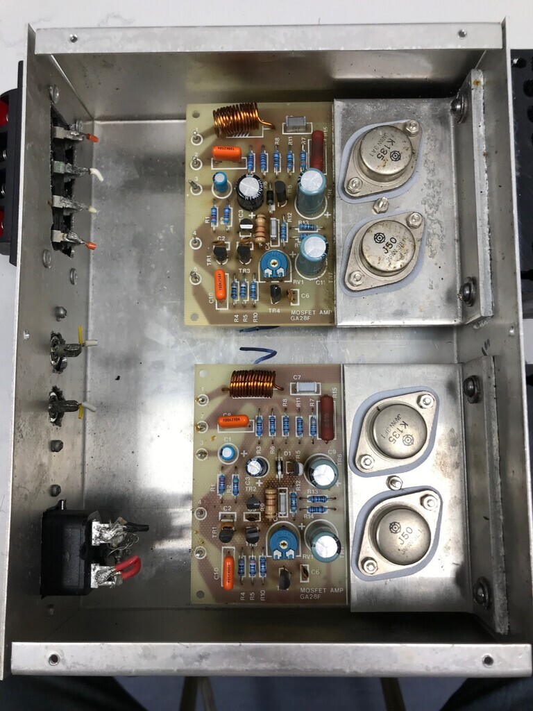 There was an unmistakable smell of old solder flux. It doesn't smell like that any more. Undid the screws and popped the amp modules out: 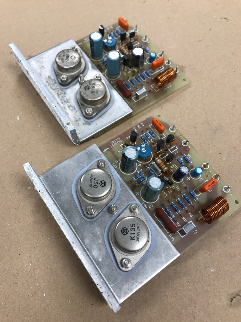 Amazingly, the heat transfer compound was still greasy and sticky. So although one of the amp modules had shaken loose, it was still in there trying to do its job. On the underside, I wasn't exactly sure what I was going to find. It wasn't fantastic, but nothing a bit of TLC couldn't fix: 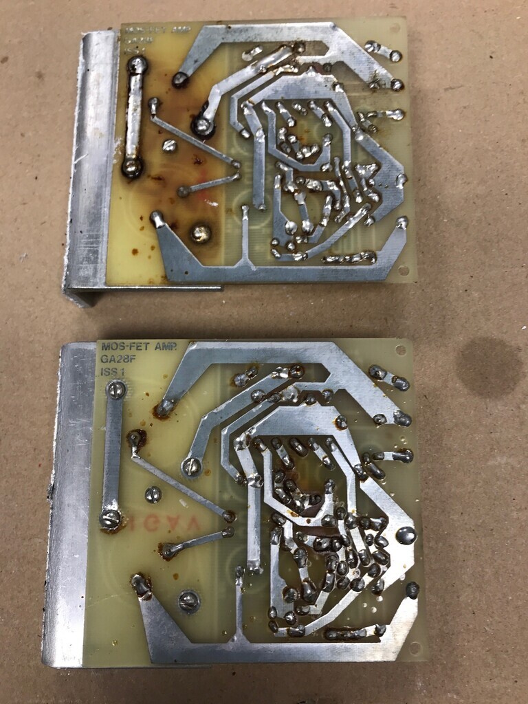 First thing I noticed was that I hadn't cleaned the flux off after soldering. I'd heard that it can be quite corrosive and it's turned the PCB resin brown where it's been sitting on it. I had a skim read through the instructions the other lunchtime and blah blah blah it said something about soldering a thick solder fillet along the track between the bolts that hold the MOSFETS on. One of them has been done but not the other, so maybe I got lucky here. One side has definitely got hot and looks a bit scorched. I'm guessing this was the side which was flapping about on its bolts. So I cleaned both boards with some IMS to try and get the old flux off. It was a bit stubborn but I got most of it. Then I clipped the unclipped MOSFET legs on one of the boards and filleted the tracks to the output: 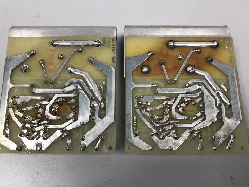 Then I drilled out all the pop rivets and you can see the true state of my hole cutting! 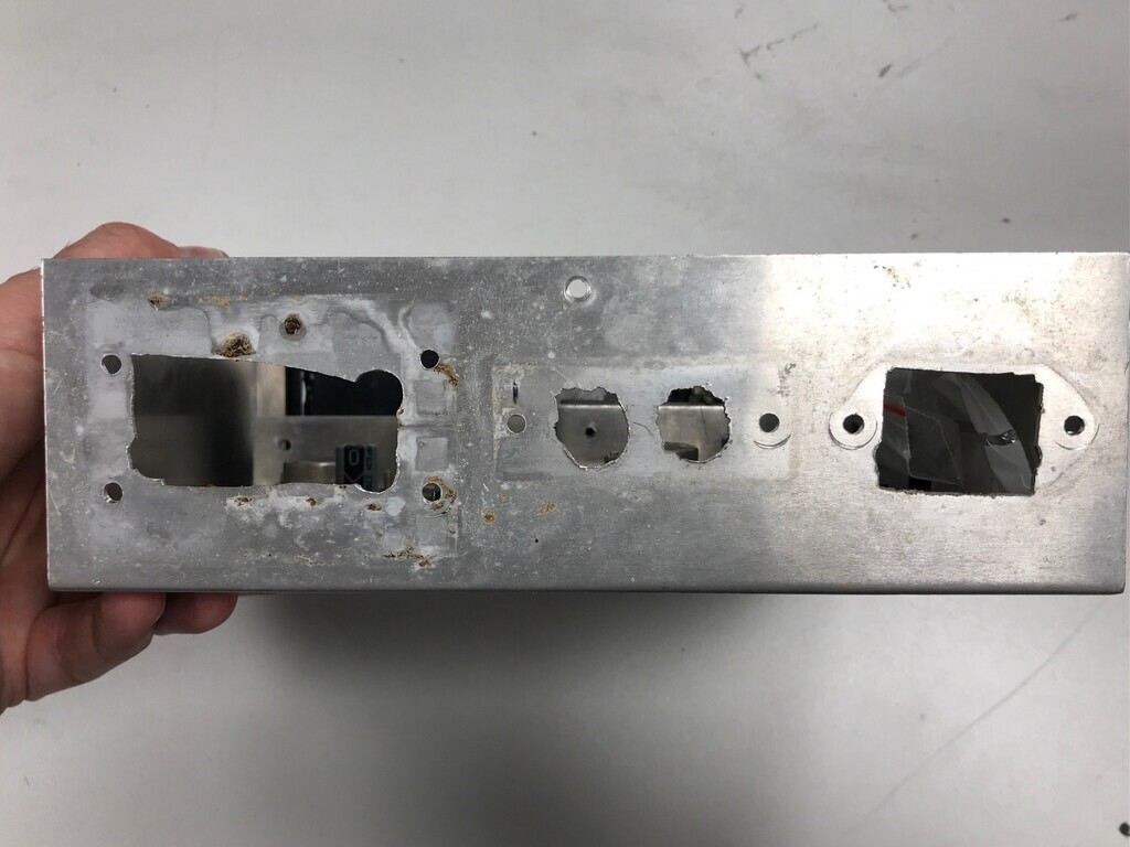 The plan is to cut most of that side of the case out. I'm going to join the two halves to make a single case and retain that side of the PSU half for shielding reasons. In the PSU side I'll add a power switch and kettle cable mains power input. The PSU could also use a fuse and could really do with the bleed-down resistors moving into that box. In the amp side I'll add a volume control and relocate the inputs/outputs. The heatsinks will then be on the far right hand side. If I've got a bit big enough, it might also get a gloss carbon fibre panel on the front. I'll bond that on with what is currently one of the strongest structural adhesives in aerospace and is used to hold modern aircraft structures and F1 cars together. |
| |
|
|
|
|
|
Jan 17, 2022 20:48:45 GMT
|
I cut that rough bit of the panel out at lunchtime and bolted the two halves together, then cut some fresh holes for the power switch, plug, volume control pot, input and speaker connections: 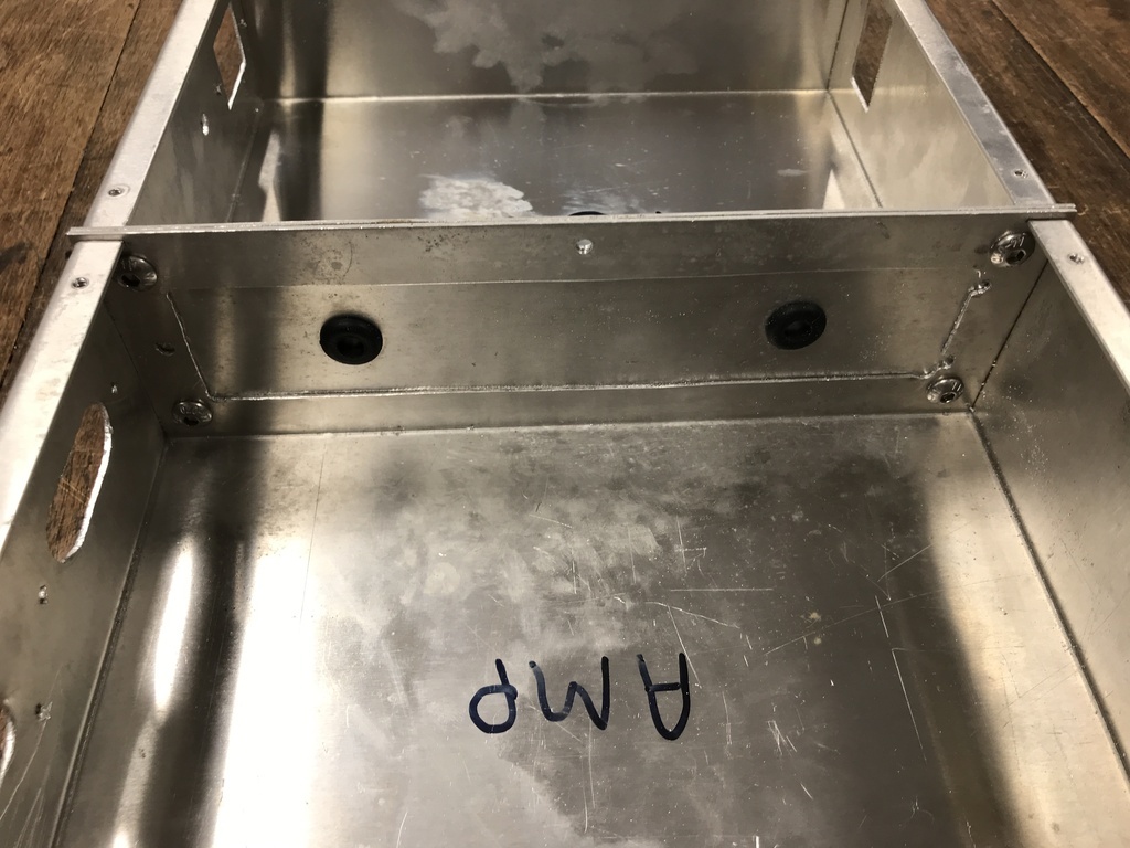 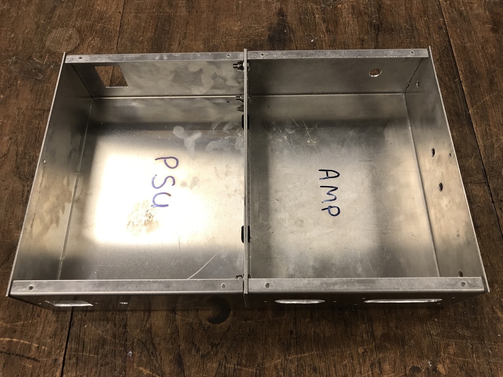 I used the same positions as the switch and pot as on the Maplin valve amp, since the aluminium cases are the same ones. I also printed these feet to go on the case screws: 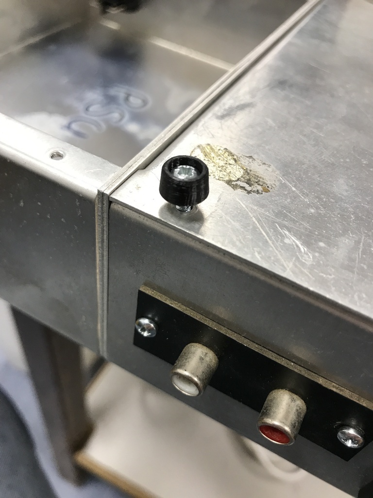 |
| |
|
|
|
|
|
Jan 19, 2022 22:25:37 GMT
|
Progress yesterday and today. Rebuilt the power supply, mounted the amps and wired it up. Here we are testing on the bench: 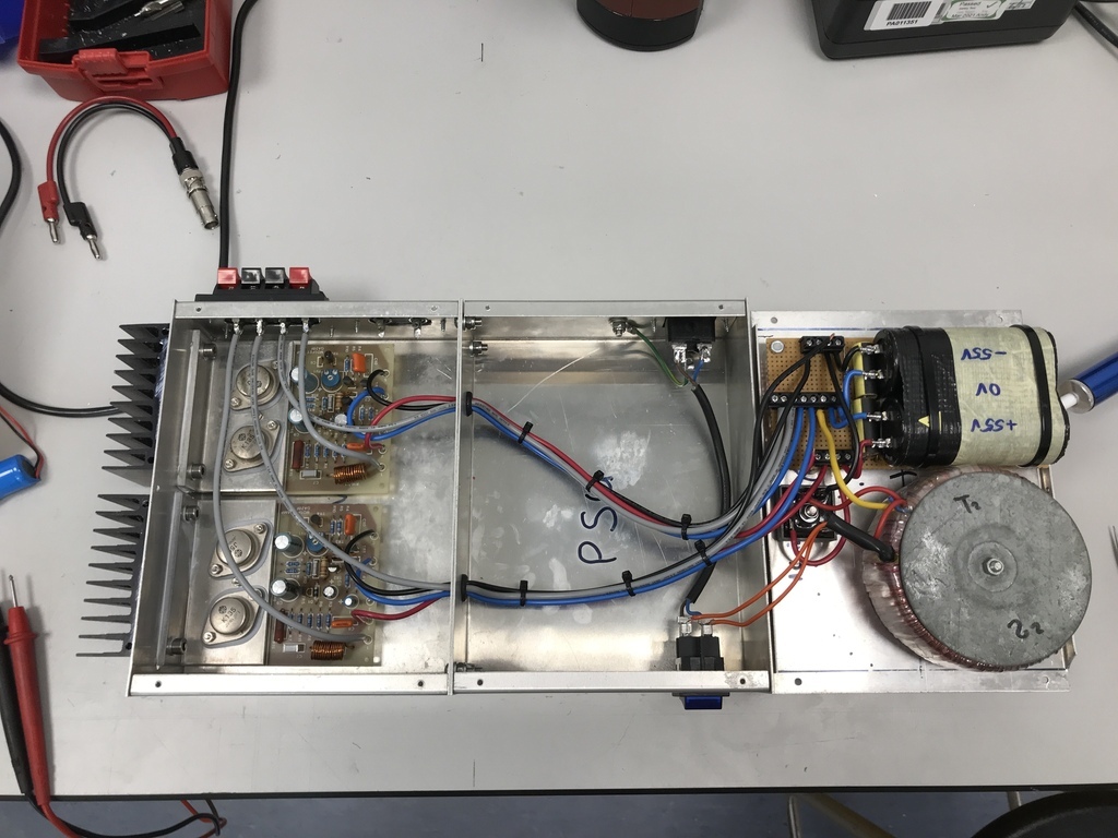 I should have taken a pic of the PSU before I started unsoldering it. It was basically hard wired, with the caps wrapped in gaffer tape and stuck down on double-sided adhesive pads: 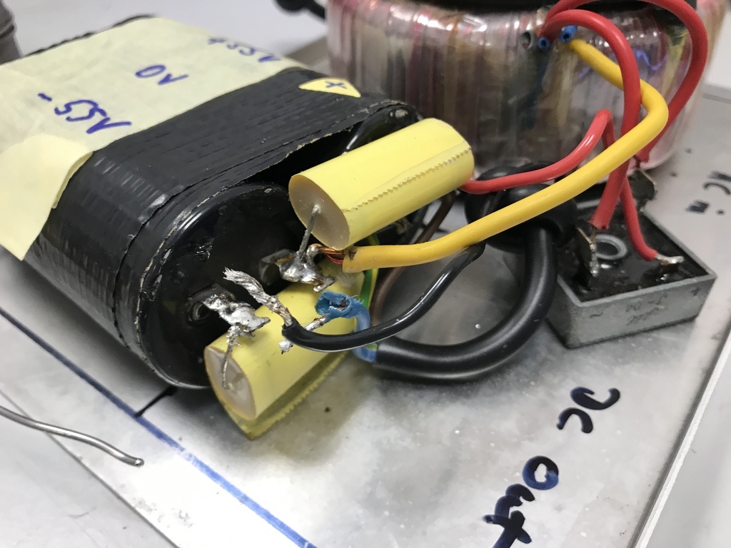 I rebuilt that on a strip board with the caps held on with ties and mounted properly on nylon PCB stand-offs: 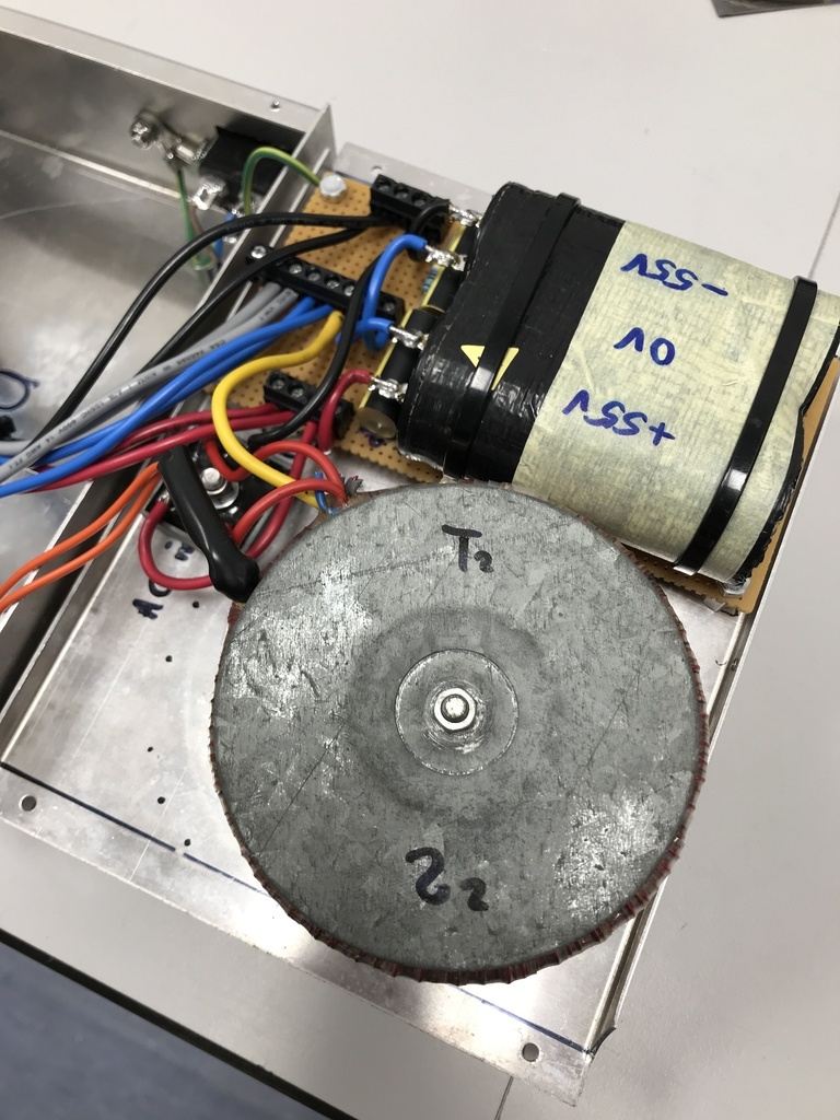 Cables all go into screw-down terminals for easier connections and testing. Fired it up and nothing exploded which was good. |
| |
|
|
|
|
|
Jan 20, 2022 18:05:39 GMT
|
^ I tested it like that to check all the supply voltages were correct and set the quiescent current. Then wired in the inputs. I used twisted pair shielded cable with the shield connected to the case (the case is earthed) and 0V and signal going down the twisted pair: 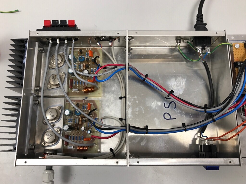 When I tested it with the input wires in, the Zobel network on the output immediately began to get red hot (it's a capacitor that dumps any stray very high frequencies into the big brown resistor near the MOSFETS). Suspecting the temporary old crusty volume potentiometer, I disconnected the inputs and made up some volume positions with fixed resistors: 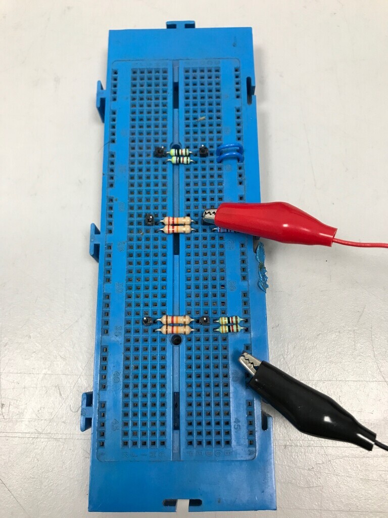 That seemed to do the trick so I double checked the resistance readings on the pot and it seemed to be fine. Only difference was the shielded wire on the inputs and the unshielded twisted wire I made up by croc clips with. So that narrowed it down to the input cable shielding, probably the earthing on it (?). So I disconnected it: 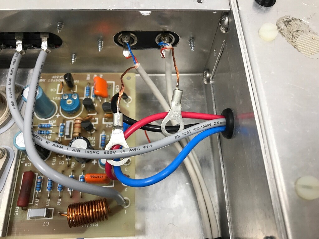 With that off, the Zobel network didn't get hot, but with a speaker attached it was humming a lot in the middle portion of the volume potentiometer. Quiet at zero volume and quiet at max volume, but a lot of hum in the middle. It was just as bad if I held the potentiometer out of the case and held the wires away from the components. Next to try was to temporarily disconnect the earth from the case. Some of the hum was still there, but the Zobel network cooked itself almost immediately. Next to try was leave the earth disconnected and connect 0V to the case. Result: silence, no hum, no hot Zobel. So that means it's earth noise. That leaves me in an annoying place. The old amp never had a volume control because it was always driven directly from my crossover or mixer. It also wasn't earthed which isn't the safest thing to do. I don't particularly want to leave this unearthed, so I'm going to have to look into some sort of 0V isolation. I think it will solve the problem but I seem to remember from back in the day that this could be bad. I'm not sure what kind of bad - I think it might be Ghostbusters don't cross the streams it could be bad kind of bad, so for now I'm not going to try that. |
| |
Last Edit: Jan 20, 2022 18:09:30 GMT by Jonny69
|
|
|
|
|
Jan 20, 2022 22:47:38 GMT
|
|
IMHO safety concerns should come before performance, so the case and any other isolated, exposed metalwork must be connected to mains earth. To do anything else is asking for trouble...which could be of the fatal variety!
I would say that 0Vdc and mains earth shouldn't be connected together, especially on an audio project.
The drain (shield) of the signal cables should be connected to 0Vdc at the PCB-end (or a slight improvement might be made connecting to the 0Vdc star-point on the PSU), and insulated at the other.
Depending on what your signal source is, you might need to add isolating transformers on the signal side before the pots.
|
| |
|
|
|
|
|
|
|
IMHO safety concerns should come before performance, so the case and any other isolated, exposed metalwork must be connected to mains earth. To do anything else is asking for trouble...which could be of the fatal variety! Agreed. First thing that came to mind was to switch it to a plastic case, then all these problems go away, but I’d really like to use the original enclosures for nostalgia reasons. I’m trying to think of a clever way of cutting out the panel the heatsinks are mounted to and re-mounting it so it’s insulated from the main case. There’s no mains in that side of the case, so it’ll be safe and hopefully look exactly the same. |
| |
|
|
|
|
|
Jan 21, 2022 10:44:18 GMT
|
I would say that 0Vdc and mains earth shouldn't be connected together, especially on an audio project. Yeah I can't remember what the reason is but I'm pretty sure this is the case. I seem to remember it was from a safety perspective rather than an earth loop / noise thing but I might well be wrong there. The drain (shield) of the signal cables should be connected to 0Vdc at the PCB-end (or a slight improvement might be made connecting to the 0Vdc star-point on the PSU), and insulated at the other. That's the only thing I didn't try. Annoyingly, once I'd worked out it was the earth on the shielding making the Zobel get hot, I cut the tags off and cut the shielding connecting the runs together (to shorten the runs) to see if it was that picking the noise up like an aerial. I'll have to re-wire the inputs to try it. |
| |
|
|
|
|
|
Jan 21, 2022 10:49:46 GMT
|
|
|
| |
|
|
|
|
|
Jan 21, 2022 14:14:37 GMT
|
Bingo. I'd written that stuff off because I thought it was really expensive. RS also do a PET-backed graphite pad which has better thermal conductivity. I think we have a plan. |
| |
|
|
|
|


 Nowadays, you can buy them on E-bay for a tenner or so.


