|
|
|
Feb 17, 2022 12:00:33 GMT
|
This is my modified circuit diagram: 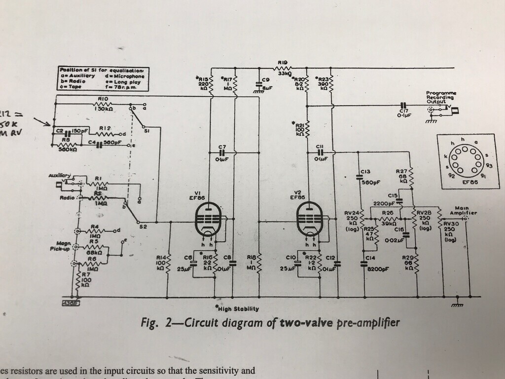 I've basically taken out the crystal pickup input for 78rpm and its associated feedback loop for the RIAA correction, same for the tape head input, and modified the microphone input so that its feedback loop (R12 on S1) is a 150k resistor inline with a preset pot so I can vary the gain. I don't need a lot of gain, so it doesn't have to be the 10M that was there originally. I wanted to use a 5M preset pot, but I only had a 1M in stock so I'll use that for now and if it's not sufficient I'll swap it for the higher value. I can simplify some of the circuit. With no crystal pickup input, R6 and R7 can become a single 1M or 1.2M resistor. I'm not planning to use the Programme Recording Output, so I'm going to omit C17 and I'm tempted to replace R20 and R21 with a single 108K or 110K resistor. All of these changes save space and a bit of wiring length. I'm also not using RV30, I'll replace that with a single 250K resistor. As well as the heaters, the common 0V bar for the inputs is soldered in. I'm hoping this isn't too close to the case to pick up noise: 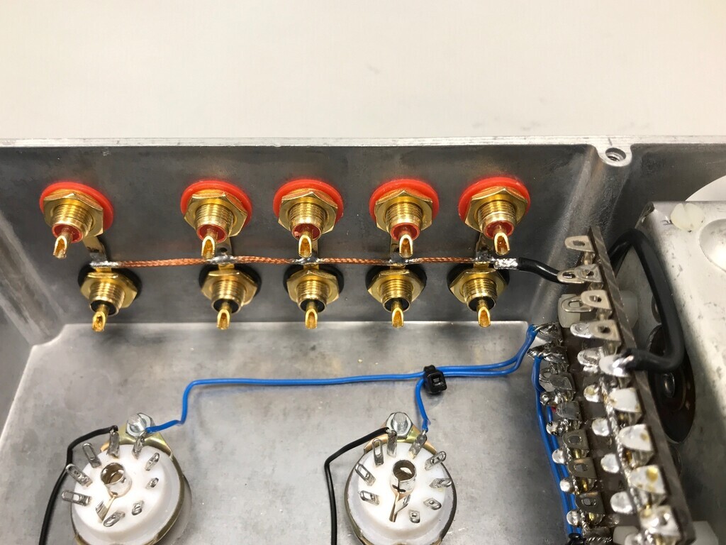 I also spotted that the rotary switch I was planning to use has enough positions but doesn't have enough poles. It's got up to 12 and I need 16: 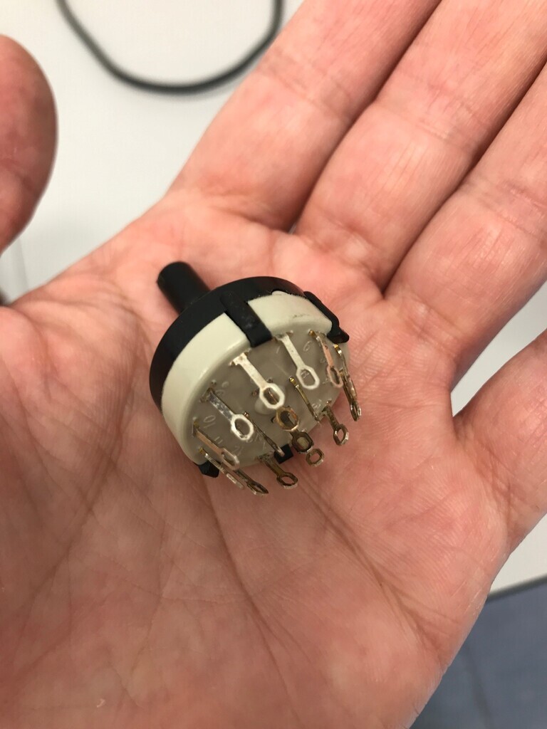 4 positions required for 4 inputs. 2 poles for stereo, plus another set required for the feedback loops. So I need 4 positions, 4 poles. I found an old wafer switch mechanism and some 6 position / 2 pole wafers. Ideal. All I had to do was set the wafer position and limit peg so it only uses the middle 4 positions. The alignment peg on the front even dropped into the same hole in the case that the rotary switch had: 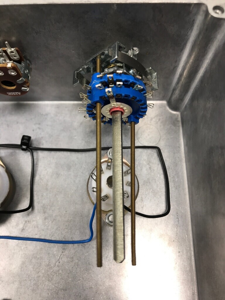 I'm no expert with wafer switches so it took a bit of fiddling and head scratching, but it works. I'm just working out where all the nuts and spacers go before assembly. I don't really want to cut the middle spline if I don't have to, but I think it's going to get in the way if I don't. |
| |
|
|
|
|
squonk
Part of things
 
Posts: 864
|
|
Feb 17, 2022 12:13:38 GMT
|
|
This is all really interesting reading. I have often considered making my own valve amplifier but my electronics education is not old skool enough to have sufficient knowledge to do so. My electronics education was as a hobbyist school boy in the 70's and a college education in electronic engineering in the early 80's. Nowadays when I have time I find great satisfaction in repairing old equipment that has been discarded due to faults. I'm currently refurbishing a couple of Goodmans 120 tuner amps (been doing so since before Covid but life keeps getting in the way). Gear from the days when Goodmans wasn't badge engineered Chineese tat but quality British equipment.
I have numerous other pieces of vintage HiFi equipment that has been 'rescued' and repaired. Trouble is I never seem to get rid of any of it so have racks of kit in the loft!!
|
| |
2004 Chevrolet Avalanche Z71
2005 Mercedes CLK320 Cabriolet
1996 Mercedes C180 Elegance Auto Saloon
1996 Rover 620Ti (Dead fuel pump)
1992 Toyota HiLux Surf
1987 Range Rover Vogue (Rusty)
1992 Range Rover Vogue SE (More Rusty)
2006 Chrysler Grand Voyager
2008 Corsa 1.4 Design
|
|
|
|
|
Feb 17, 2022 22:50:41 GMT
|
It worked out with the wafer switch. I had the correct spacers and nuts, then when I’d clipped the threaded bits it was clear of everything and I can leave the spline uncut. I wired up the tagboard for the inputs and feedback loops. It’s my first time using these and it feels a bit like they’re not really designed for modern style components. It feels like they really need the older style resistors and capacitors which are larger and have much thicker legs. Coupled with the fact that I’m not using thick single core wire, I decided to modify the layout a bit. The original design uses a lot of point-to-point wiring. The old-style components lend themselves to this because they can span a decent distance and the stiffer legs means they’re self-supporting. Not much of mine is self-supporting, so I had a think about how to do it logically. I decided the best line of attack was to have the inputs and feedback running down the side of the case, so they can come out the RCA sockets and straight into the input resistors, then into the wafer switch, split into the valves and back into the feedback loop. No power needs to go over that side. I also decided that the short tagboard I’d hung on the side of the power supply didn’t have enough connections: 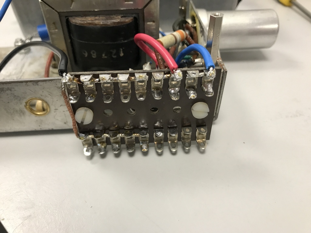 The HT doesn’t go straight to the valve. It has resistors and capacitors and as these ones can’t really dangle in mid air I decided to extend the tagboard to tie them down, so that short 2x9 one came off and it’s now a full 2x18 one. That side can now deal with all the power and biasing, as well as the 0V bus bar. I can also stack another short tagboard on top. The input board currently looks like this: 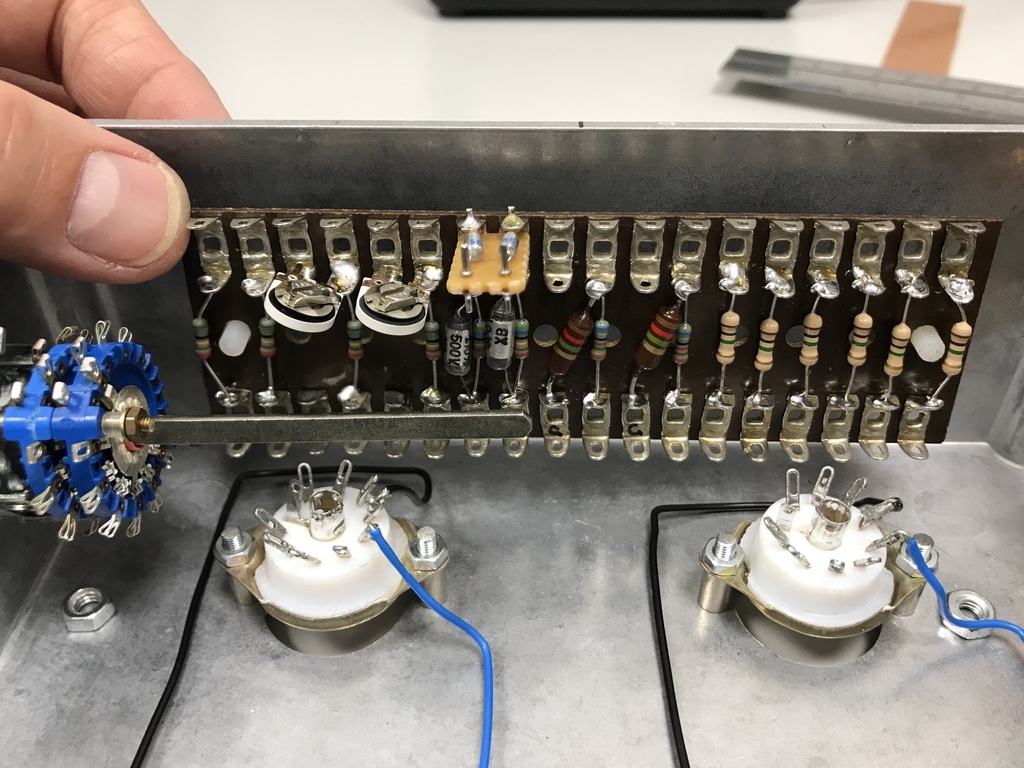 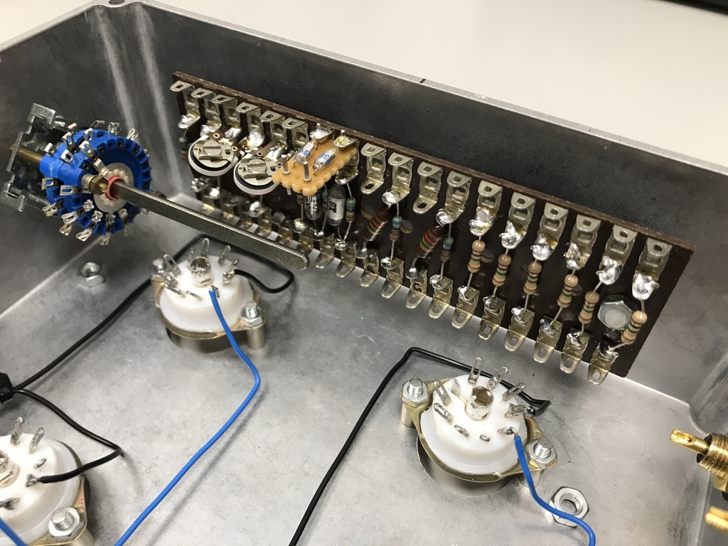 I extended the phono RIAA on a small piece of stripboard with PCB pins to connect it to the tagboard. Note the two preset pots which can trim in an extra 1M ohm to amplify the third input: 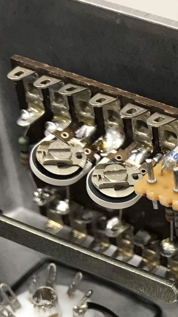 I’m going to wire the tone circuit on stripboard mounted directly on the pots. It keeps it neatly out the way and in its own discreet section. I’ve just got to work out which is which and what direction they operate, because once they’re wired in it’ll be almost impossible to swap it around without starting again from scratch. |
| |
|
|
|
|
|
Feb 18, 2022 22:36:07 GMT
|
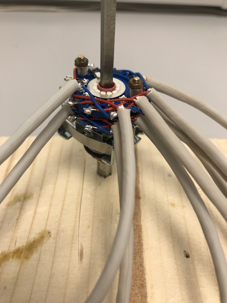 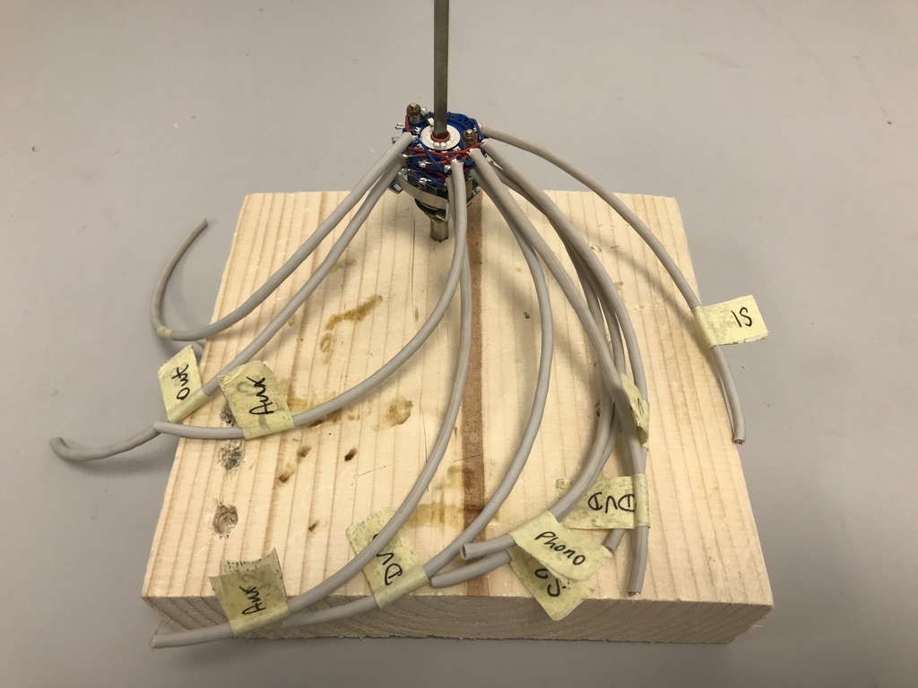 I’ve decided there’s a new fiddliest job in the world ever. It’s called wiring wafer switches. 20 teenie tiny little wires and a balding middle aged bloke with fat fingers and deteriorating eyesight. I now officially love my lab tweezers; this would have been impossible without them. 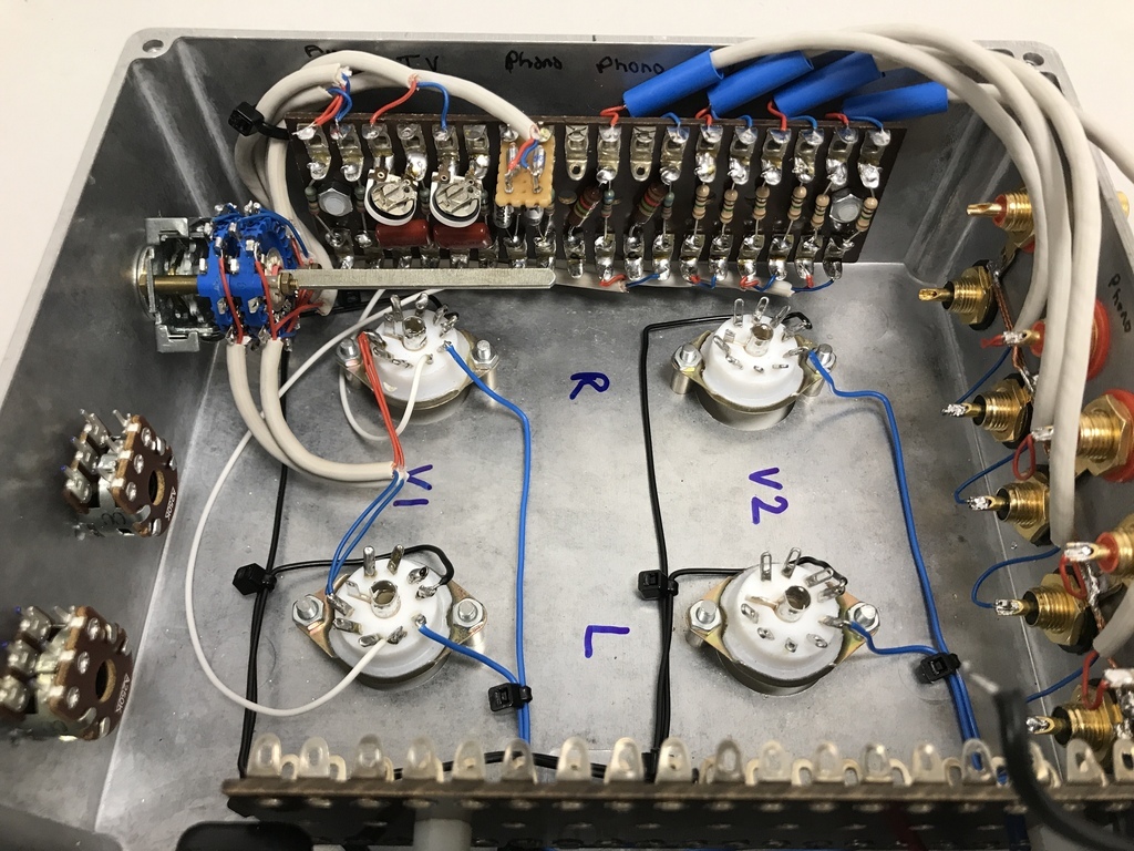 It’s starting to take shape. All the input wires are soldered in and both halves of the wafer switch are wired to the input resistors and feedback loops. I’ve got to say, this was a pretty fiddly job. To make sure I don’t miss any connections on the circuit diagram, I’ve started highlighting the bits I’d done. I recommend doing this. The circuit is quite simple but there are a lot of connections with a stereo pair and it’s easy to forget something. I knew I’d need most of the new, longer tagboard on the PSU side for the network of resistors splitting up the HT. That just left a couple of 0V / GND resistor-capacitor pulldowns (C6 & R16 and C10 & R22 on the cathodes) that it didn’t look like I had space for. That’s where I decided to stack on the break-out tagboard to mount those components: 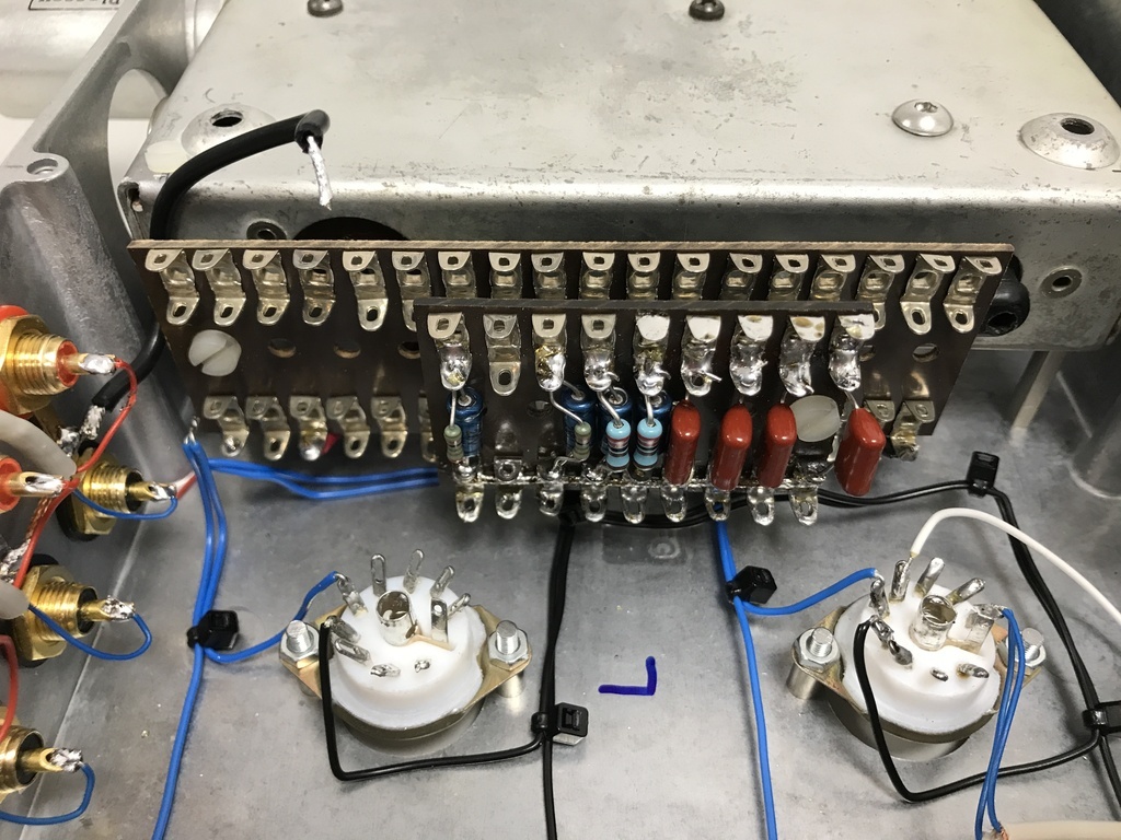 So quite a long lunch break getting those bits on but it’s starting to take shape. |
| |
Last Edit: Feb 18, 2022 22:52:49 GMT by Jonny69
|
|
|
|
|
Feb 19, 2022 11:59:03 GMT
|
This is all really interesting reading. I have often considered making my own valve amplifier but my electronics education is not old skool enough to have sufficient knowledge to do so. My electronics education was as a hobbyist school boy in the 70's and a college education in electronic engineering in the early 80's. Nowadays when I have time I find great satisfaction in repairing old equipment that has been discarded due to faults. I'm currently refurbishing a couple of Goodmans 120 tuner amps (been doing so since before Covid but life keeps getting in the way). Gear from the days when Goodmans wasn't badge engineered Chineese tat but quality British equipment. I’ve got to say, this has really challenged me. Not just getting back up to speed how valve circuits work, but figuring out where everything is going to go with a stereo pair. I thought I’d been generous with the case size and it only just all fits. I think the main thing I underestimated was how much time it would take. It would have been a pretty serious undertaking to build one of these in the 50s, even a mono setup. My electronics education was much like yours but in the early 90s, then a bit on university projects and an occasional bit at work. I don’t know where the fascination with valves came from. We had a couple of old valve radios at home but I never poked around in them. All the amps I built or came across were MOSFETs or big bipolar transistors. |
| |
|
|
|
|
|
Feb 22, 2022 10:35:43 GMT
|
Some candy in the post. 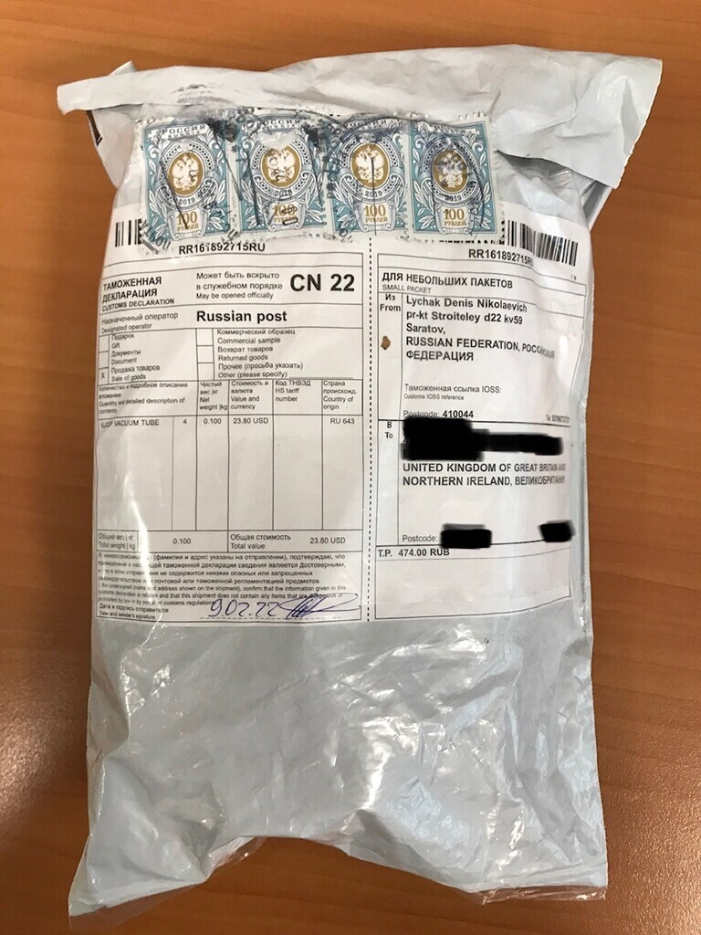 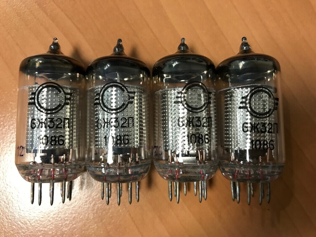 Matching batch NOS Russian 6J32P valves, same as an EF86, direct from Russia. Mad to think that we might officially be at war with these people later today. |
| |
Last Edit: Feb 22, 2022 13:47:54 GMT by Jonny69
|
|
|
|
|
Feb 24, 2022 20:56:34 GMT
|
Chipping away at the wiring. The HT part of the circuit is on the bigger board at the back. This is basically the upper part of the circuit diagram where everything is at high voltage, plus the additional smoothing capacitors for the power supply which are specified in the text but not shown on the circuit diagram. In the case, these are tucked under the power supply so you won’t see them. The smaller board on top of it is essentially the lower half where everything ties down to 0V ground: 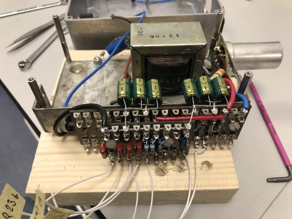 I had to take the power supply in and out a few times before I got that right. With it back in place, I could start wiring the valves in with point-to-point wiring: 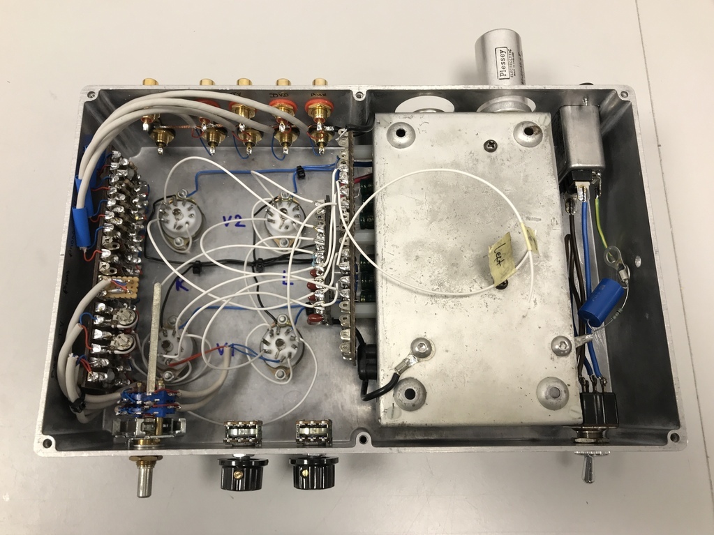 I could have loomed those together in a bunch, but I couldn’t decide if, by doing so, it would make it noisy. In theory, the only bit which would generate noise is the heater wires (the blue ones), but it would be a lot of high voltage carrying wires running alongside sensitive low voltage wires running back to ground. I think I’ll leave them looped for now and I can bunch them later once it’s up and running. Next job: make up the tone control section which is going to mount directly on the pots. |
| |
Last Edit: Feb 24, 2022 20:58:02 GMT by Jonny69
|
|
|
|
|
Feb 25, 2022 19:59:54 GMT
|
Started to tackle the tone control after work. I couldn’t get straight on with it because I didn’t know which pot was bass and which was treble and it didn’t say anywhere in the text. I’d made a guess based on where the capacitors were but I’m bit rusty on that sort of thing. Also wasn’t fully sure which direction up or down was boost or cut, so I stuck it on a breadboard to check and played some music through it: 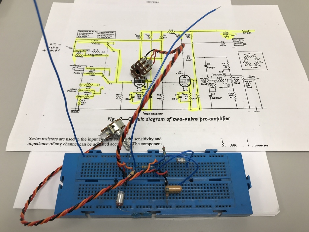 Left hand pot on the diagram is treble. Up is boost. I also swapped all the screws to M3 countersunk hex heads, which looks loads better. |
| |
Last Edit: Feb 25, 2022 20:04:49 GMT by Jonny69
|
|
|
|
|
Feb 26, 2022 12:50:43 GMT
|
|
Cool. I have a very similar breadboard (same colour, at least), also with a pot/switch holder that clips on.
|
| |
|
|
|
|
|
Feb 26, 2022 17:01:54 GMT
|
Cool. I have a very similar breadboard (same colour, at least), also with a pot/switch holder that clips on. The pot/switch holder sounds useful. Got a pic of that? I twisted up some red/black/orange wires with the drill and soldered on some PCB header pins to shove into the breadboard holes. |
| |
Last Edit: Feb 26, 2022 18:28:53 GMT by Jonny69
|
|
|
|
|
|
|
|
|
Here's a shot of it:  P1030485 P1030485 by mtjhunt, on Flickr The smaller holes are for LEDs, etc. |
| |
|
|
|
|
|
Feb 28, 2022 22:36:10 GMT
|
Had a crack at getting the tone control onto the board: 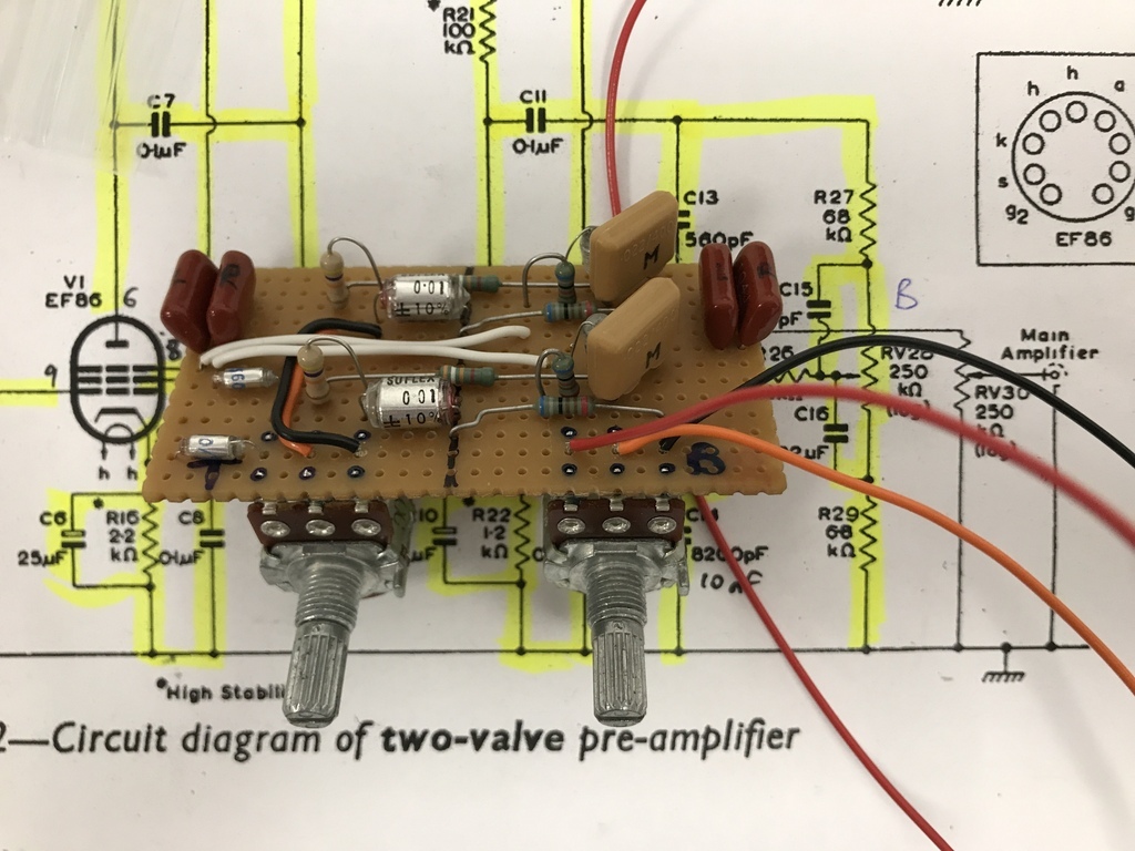 That was quite challenging because the board is only just big enough. Still needs a few tracks breaking on the underside but I think it’s basically complete. |
| |
|
|
|
|
|
|
|
This is the finished tone control module. Tested and working, seems to be noise-free: 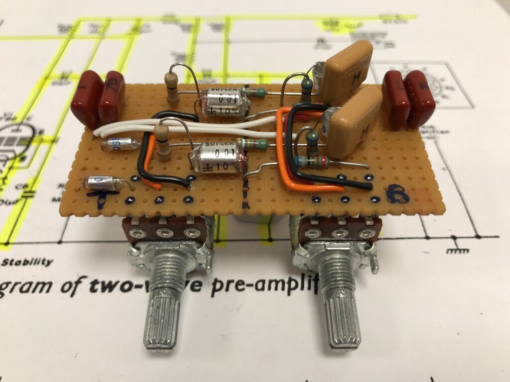 I wanted this to be a sort of drop-in module, so if I wanted to modify the sound I could do something like unslot the board and slot a different one in without actually dismantling anything or unsoldering wires. The space constraints meant this wasn't really realistic, so this is close enough. I could theoretically make another one of these with different components and test it separately, then just swap it over. Below pic is it fitted up. It's not completely obvious but any bigger than that and I can't physically get it in position: 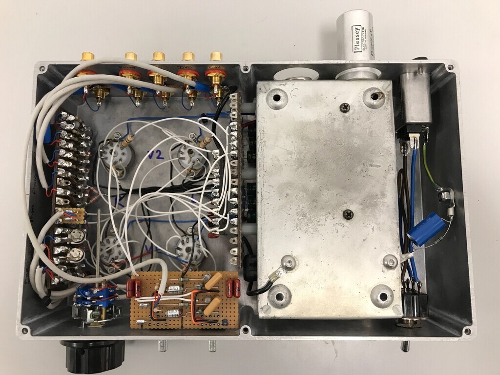 It's basically complete now and ready to test. I can't fit everything and flick the switch, however, as it's too risky with the high voltages involved. First I'll power it up with no valves and do a few basic safety tests like earth continuity etc. Then I'll do the same with the rectifier valve in place. Then there are some voltages to check at various places e.g. heaters, HT voltages at the anodes and a couple of grid points, and at the signal output. Then it'll be ready to fit the valves and try it out. |
| |
|
|
|
|
|
|
|
Tested at lunchtime and holy carp it works! 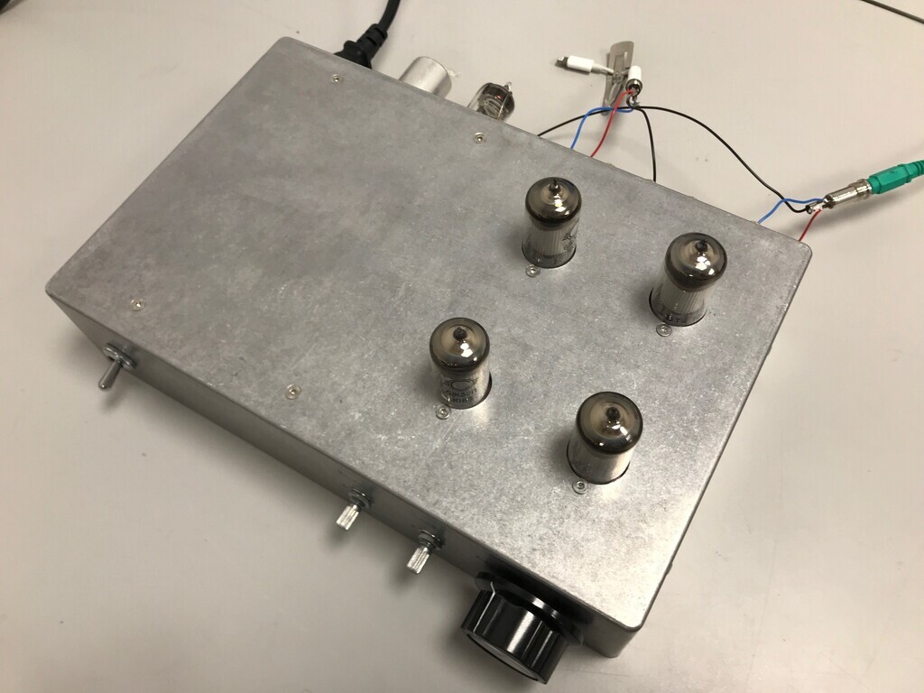 Probably comes as no surprise that I needed to adjust the earthing arrangement. It also makes quite a thump when switching between inputs, so I need to work out a way of snubbing that. Probably just needs the inputs to be tied to 0V, because they're currently floating. Next stop: connect to the MOSFET amp at home to see if they're compatible and check the output levels are sufficient to feed the amp. |
| |
|
|
stealthstylz
Club Retro Rides Member
Posts: 14,960
Club RR Member Number: 174
|
|
|
|
|
No idea what is going on with any of this but it looks like something a sweating man with a shaky hand would be having indecisive moment about which wire to cut so it's super cool.
|
| |
|
|
|
|
|
|
|
Finished pictures. 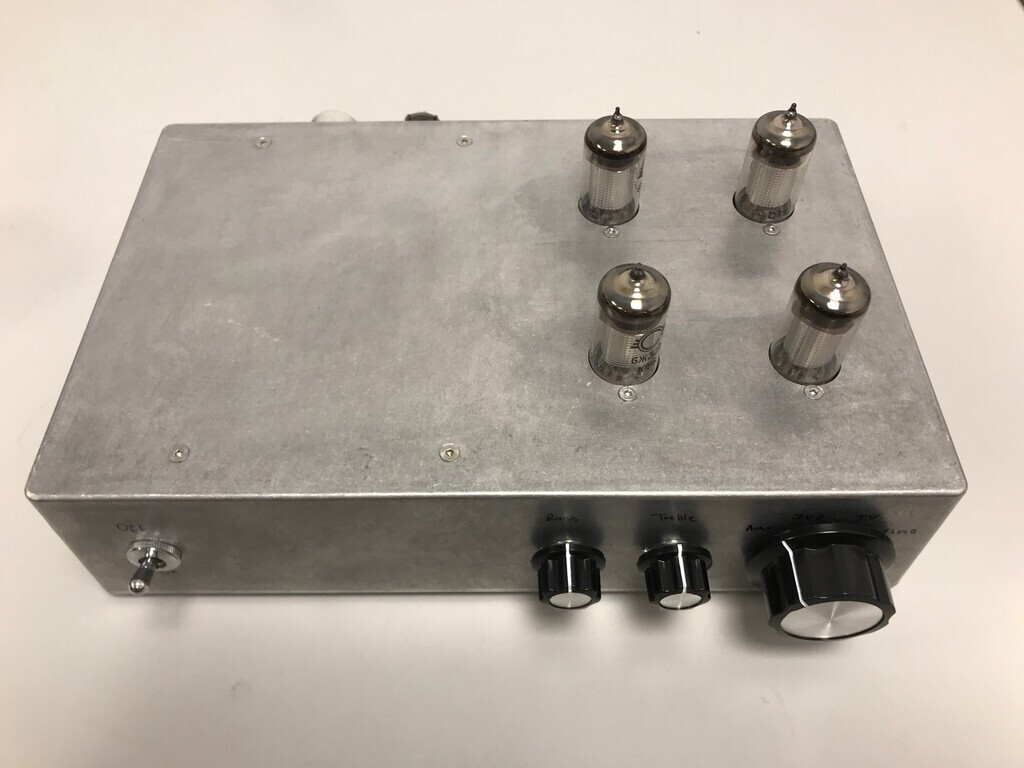 And in situ: 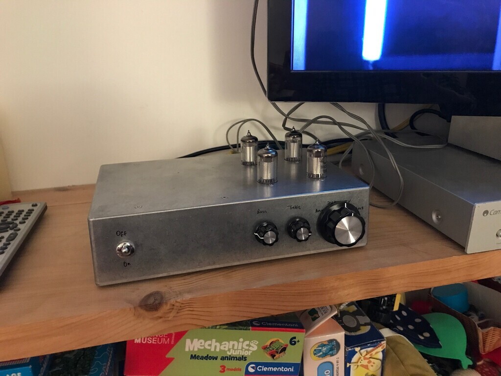 I definitely don't like the switch and it's not obvious that it's switched on, so it's going to get an illuminated rocker switch like the other amps. I'm also thinking about changing the knobs. I got a chance to test it on the amp. The output is slightly low, so I'm going to amp it up a bit internally to give it a bit more attack. Referring back to the circuit diagram: 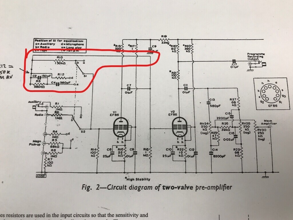 Where you can see R8, R10 and R12 circled in red on the top left hand side of the circuit; increasing the values of these resistors increases the level of amplification. I've already put a variable resistor (1M preset pot) inline with R12 to raise the level of the TV input. I estimate I probably need to set this to about 100-200k to get it to the same level as everything else. Since I need to raise the level of all of the inputs as well, I think the easiest way to do this is to insert a resistor in the line which runs above R10. This is a wire link in the actual preamp. I might be able to make this a variable resistor if I have one and if I can find somewhere clever to mount it. In terms of sound quality, it sounds pretty good. The bass boost is indeed a bit high up and I will look at changing the capacitor to drop it down the frequency range a bit. The treble boost is spot on for my big speakers. There's a tiny bit of mains hum. It's quite soft-sounding and I can cut it by turning the bass pot down to cut the bass, so I suspect it's being picked up by a wire passing something carrying AC. Therefore it's probably one of the heater wires causing this. Two things I can do about that: 1) re-position the wires near the 6V AC heater lines so they aren't too close to other each other and/or 2) rectify the heaters so they run on DC. All in, a good start and only minor tweaks needed. |
| |
Last Edit: Mar 3, 2022 12:18:28 GMT by Jonny69
|
|
|
|
|
|
|
it looks like something a sweating man with a shaky hand would be having indecisive moment about which wire to cut To be fair that's a pretty accurate description of me when I'm poking around inside it with it switched on! |
| |
|
|
|
|
|
|
|
I set about tackling the amplification as mentioned above. I added a couple of 470k preset pots inline with the wires that went to the valves: 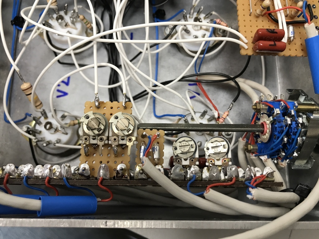 Slightly curiously, they had no effect at all and this led to a lot of head scratching. Especially because the pots on the TV input work a treat and I couldn’t work out why these ones wouldn’t. Eventually I narrowed it down to the fact that I’d put them on the wrong side of the 0.1uF capacitor. I couldn’t splice them in anywhere else, so I had to add some extra boards at the top like so: 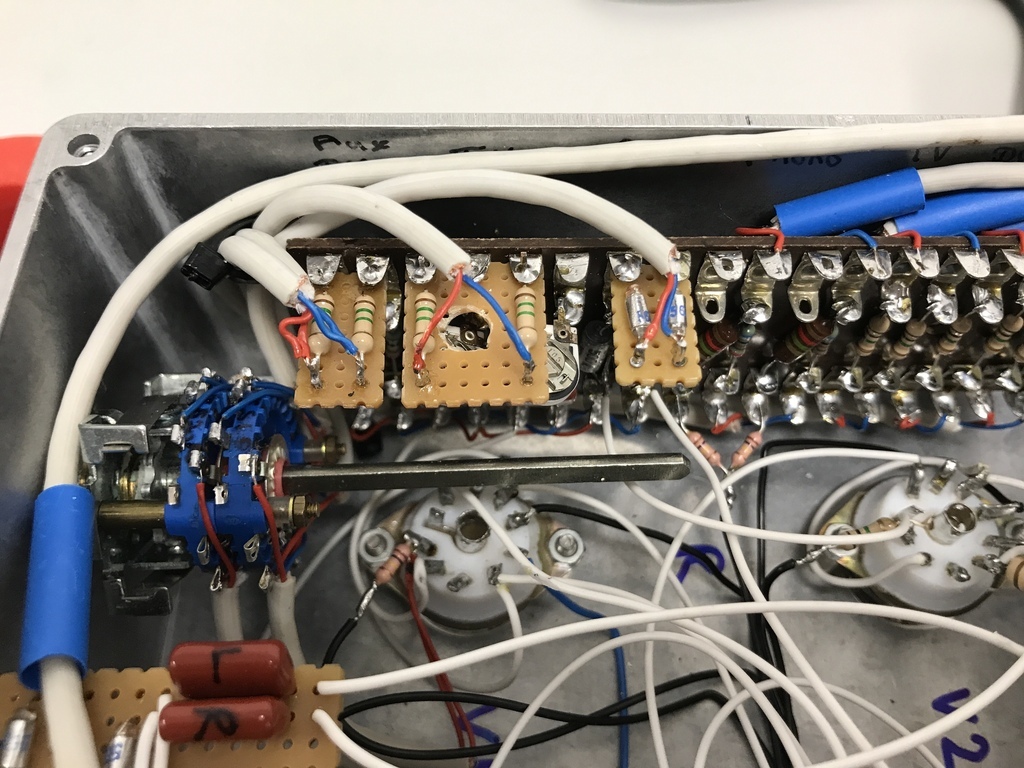 Initially, these didn’t work either and by that point I was getting really confused. I resorted to measuring the resistor values and found they were reading zero - curious. Then I realised what I’d done, which was that I hadn’t cut the tracks under the resistors. Once I’d done that, it worked as expected. The main annoyance though, is that with all the faffing resoldering things, I’ve touched a few wires and it doesn’t look as nice as it did before. But anyway. It works great now with a 1.5 MOhm resistor inline. Just going to meddle with the bass boost cap and it’s basically done. |
| |
Last Edit: Mar 4, 2022 21:59:20 GMT by Jonny69
|
|
|
|
|
|
|
Next on the project list is this: 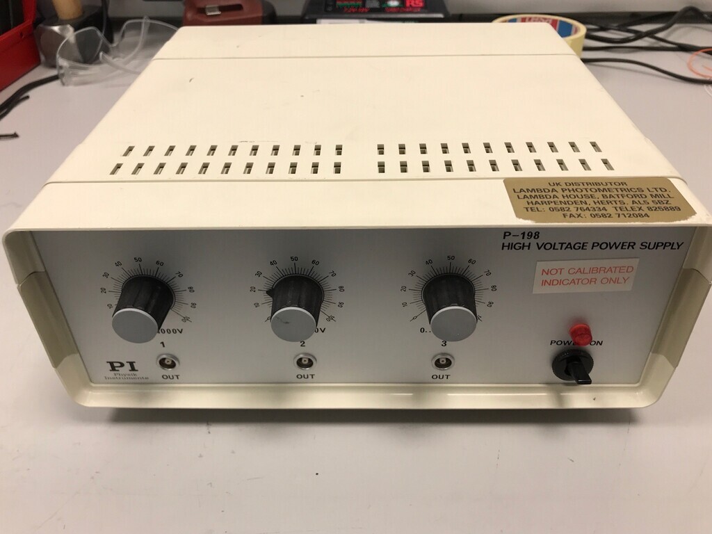 It's a variable 0V-1000V DC power supply with three outputs which was being binned - ideal for a valve test power supply for future projects. Or at least I thought it was. It's actually a 0V to -1000V DC supply, which is a bit strange and not much use. However, it's quite simple inside and I'm thinking it probably wouldn't be too difficult to modify it to 0V to +1000V. This is what's in the box: 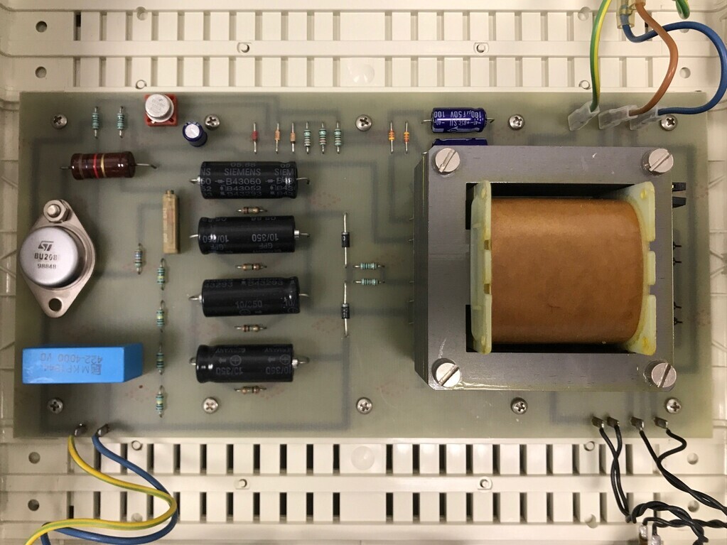 It's a DC boost converter, similar to a DC buck converter but boosts the voltage instead of reducing it. I've only had a very brief look, but the only real difference between the Wikipedia circuit description for a +ve boost converter and this one seems to be that this one switches low, the diode is round the other way, and there are four capacitors in series to bring it up to 1400V. It's coupled relative to earth, so I can't just swap the terminals round inside, but what I can do is swap it to switch high (if I even need to) and turn the diodes and capacitors round the other way. Then it ought to kick out three lots of 0-1000V DC. Exciting that I might die doing this. It'll supply 100mA at 1000V which I'm pretty sure will kill instantly at that voltage. |
| |
Last Edit: Mar 7, 2022 11:08:29 GMT by Jonny69
|
|
|
|
|
|
|
|
Nice job on the amp, at least you can actually see the components without the need of a magnifying glass!
Think you might of got the valves just at the right time...
|
| |
|
|
|
|


