|
|
|
|
|
I’ve made a list and there’s loads of interesting valves. Loads of stuff I don’t recognise and don’t understand so I’ve got a bit of learning to do. Couple of interesting ones here:  These are magic eye indicator tubes like the ones I used in the VU meter I made in my other thread. Left to right: Mullard EM81, Mazda EM84, Mullard EM84. The EM81 is almost identical to the EM80/6E1P tubes I used, it’s just slightly more sensitive and requires less voltage to drive it. The EM84 tubes are slightly different, they’ve got phosphor strips down the front so will probably look a bit more like a VFD tube. I was hoping they’d be interchangeable with the EM80 tubes so I could try them out in the VU meter and see what they look like, but the pinout is different despite all the drive voltages being the same. Why would they do that? Anyway, more importantly, why am I posting about these and not something interesting like a double diode hexode? Well, these were originally used in radio sets as a tuning aid. When you hit the peak of the tuning frequency, the green fan would open up to let you know you were on it. I’m wondering if I can make some kind of tuned circuit which resonates when a given frequency is played through it and makes the fan open. This would be used as a tuning aid, say at 512hz for C or 440hz for A or whatever they are (I’m no music man). I think this might actually look something like an AM radio circuit just with lower frequencies, so maybe I might be able to make use of some of the radio valves. |
| |
|
|
|
|
jimi
Club Retro Rides Member
Posts: 2,220 
|
|
|
|
|
What surprises me is how many valves are still about, considering how long it is since most of them went out of production.
That HD24 number rings a faint bell, big valve with a top contact ? I think one of the old valve radios I had back in the sixties used it.
I used to buy old radios at jumble sales for a few shillings, sometimes they worked, sometimes I was able to get them working, lovely wood and bakelite sets, with a great sound. I used to listen to Radio Luxemburg on them at night while doing some my homework.😎
|
| |
Last Edit: Jul 5, 2023 21:38:30 GMT by jimi
Black is not a colour ! .... Its the absence of colour
|
|
|
|
|
|
|
That HD24 number rings a faint bell, big valve with a top contact ? I think one of the old valve radios I had back in the sixties used it. Couldn’t remember which one that was so I just popped the box open. There’s two really pretty radio valves in the big boxes and this is one of them.  Yeah it’s true what you say about how many valves have survived. Most amazing is how many NOS ones there are, in their original boxes and everything. |
| |
|
|
jimi
Club Retro Rides Member
Posts: 2,220 
|
|
|
|
|
That's a very nice looking valve, looks very like the picture in my head (less the label) Your right about the NOS valves, truly amazing how they keep appearing, must have been manufactured in large quantities back in the day + I suspect the reliability of valves has helped with the spares survival. 😎
|
| |
Black is not a colour ! .... Its the absence of colour
|
|
|
|
|
Jul 12, 2023 16:52:30 GMT
|
Contents: .. 9) Some kind of Nixie clock display thing one dayAaah, this almost made an unexpected start: 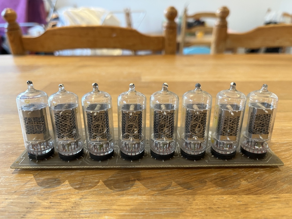 I spotted someone on eBay selling boards pulled out of old kit with lines of German nixie tubes. This was supposed to have 6 number tubes and two symbol tubes, ideal for a nixie clock, but it’s actually got 5 number tubes, one symbol tube and two random-looking letter tubes. The nixies are way too obscure to find another nice match and the board has been properly hacked out of whatever piece of kit it came from (which wasn’t shown in the pictures), so I’m going to have to send it back. To Bulgaria. In other news, I tried out a bit of tube swapping in the VU meter. The ECC83 I used for the signal amplification was from my Maplin amp and part of a pair for that amp, so I didn’t want to keep it in the VU meter for too long to save wearing it out in relation to the other one. I had originally planned to use one of the 6E1P valves I bought and modify the heater wiring. However, I bought that huge box of valves recently and have a few spare ECC83s and other similar dual triodes. I thought I’d have a play with some of them: 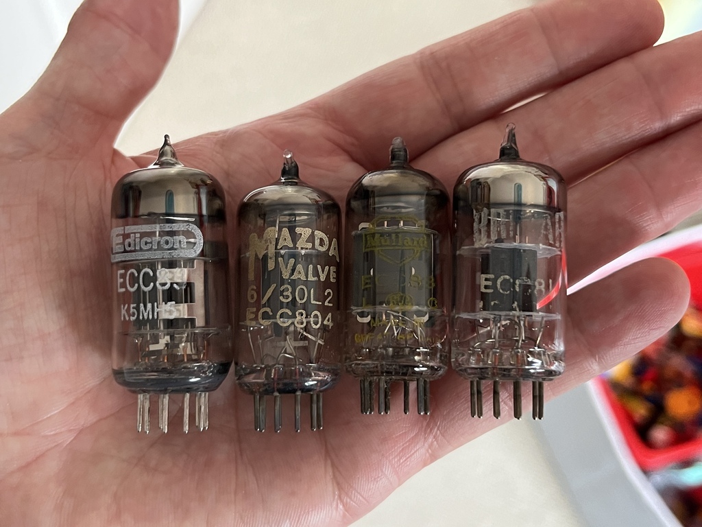 Left to right: 1) the Edicron ECC83 from the Maplin amp, 2) Mazda ECC804 (a television dual triode), 3) Mullard ECC83, 4) Brimar ECC81. The original design that I modified used an ECC81. It’s essentially part of the same range of audio dual triodes as the ECC83 just with lower gain. I wanted to try that one first and sure enough it worked almost identically just with less movement on the magic eye tubes. The next one I wanted to try was a radio frequency (RF) triode. I wanted to see what it did at audio frequencies instead of RF. Well it didn’t work when I plugged it in. Looked like the heater was dead at first, but when I looked it up on the datasheet it’s just got different heater wiring to the ECC83. I have others in the box I can have a go at this with. In the meantime I’ve swapped in what looks like a generic ECC83 and kept the Mullard one aside for an audio project. Also in the box is an Edicron EL34 which is identical to one of my originals that popped. That means I have a matching set of four of those again. I also have some small-signal RF pentodes that I’d like to swap into the preamp to see what they do. I think this is officially called tube rolling… |
| |
Last Edit: Jul 12, 2023 17:31:21 GMT by Jonny69
|
|
|
|
|
Jul 19, 2023 19:06:28 GMT
|
Wow, it’s nearly been a month since I marked up the box. I drilled some holes after work and got the power supply mounted up: 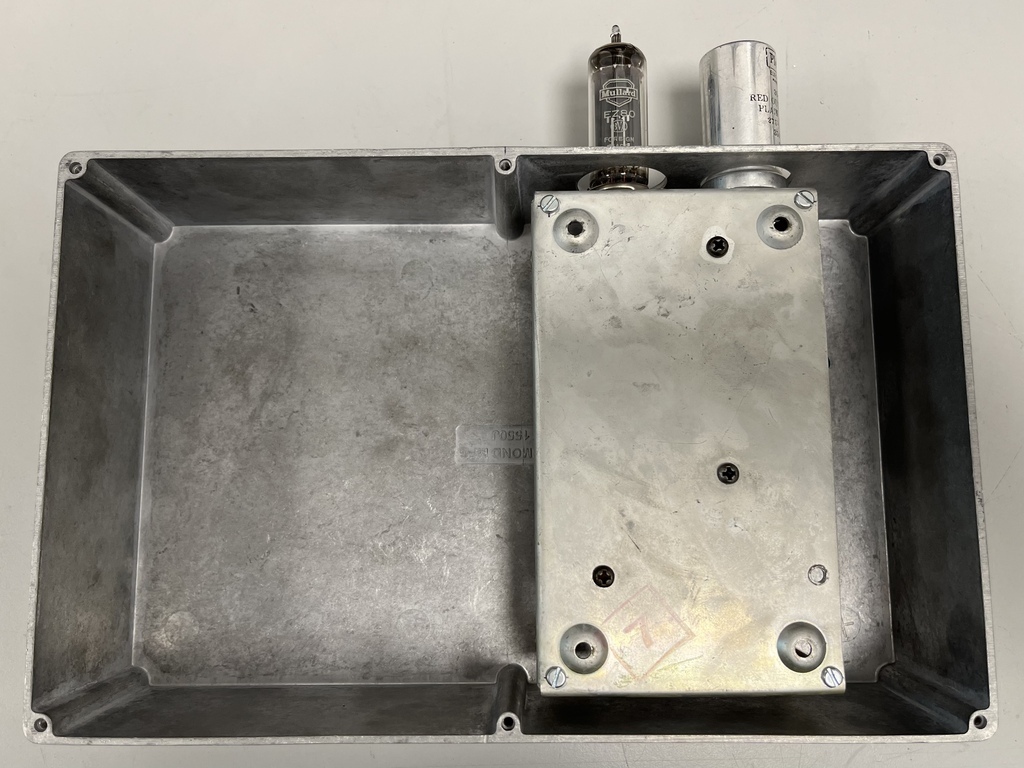 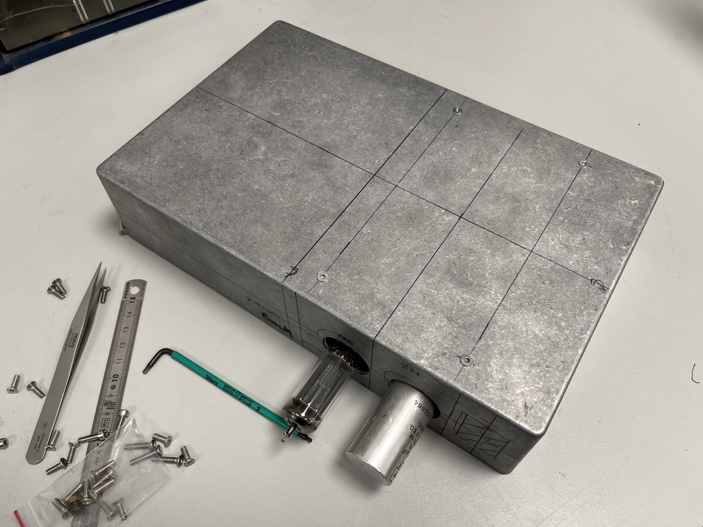 Just reiterating, it’s in exactly the same place as the one in the pre-amp. Space down the side for a filtered IEC socket at the back and power switch at the front. I’ll have to do some clever squeezing to squeeze in the variable capacitor and all the valves and I’ve sort of not really thought about where the jack sockets are going to go. Cross that bridge when I get to it… |
| |
|
|
|
|
|
Jul 21, 2023 13:02:13 GMT
|
Total valve count so far is 2x pentodes for the oscillator, 1x dual triode for the square wave, 1x pentode for the transitron circuit and possibly one more pentode or dual triode for an additional amplification stage. Just thinking out loud while I'm planning the chassis layout for the valves. Mostly seeing if I can eliminate a valve by using a combined triode-pentode in the transitron circuit instead of using two separate valves - and of course making a note of it here so I don't forget. In my stash I've got the following triode-pentodes: ECF80: www.r-type.org/pdfs/ecf80.pdf Triode on the left and pentode on the right. I'm pretty sure I can't use this because the cathode and g3 in the pentode side are internally connected and I need to tie the cathode to ground and couple g3 to g2 with a capacitor as per below: 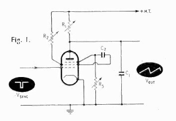 Plus, I can't quite see clearly, but I think the pentode's anode might be internally connected to the triode's grid, so the triode would need biasing up to match the pentode anode voltage. Or something. I'd have to stick a continuity meter on the pins to confirm. Edit: closer look it's probably not connected... PCF80: www.r-type.org/pdfs/pcf80.pdfHas the same internal cathode and g3 connections as the ECF80, but has the added complication of having a 300mA heater for series connection so it needs a different heater voltage. P-series valves all have a fixed 300mA heater so they can be connected in series. That's that one ruled out. PCF200: www.r-type.org/pdfs/pcf200.pdfThis is a possibility. Has the separate connections I need, but has a 300mA heater and a 10-pin B10B base which I'm not familiar with: 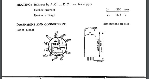 PCF801: www.r-type.org/pdfs/pcf801.pdf PCF801: www.r-type.org/pdfs/pcf801.pdfHas internally connected cathodes so I think it won't work. Plus 300mA heater:  PCF802: www.r-type.org/pdfs/pcf802.pdf PCF802: www.r-type.org/pdfs/pcf802.pdfSame internal cathode and g3 connections as the ECF80 and 300mA heater: 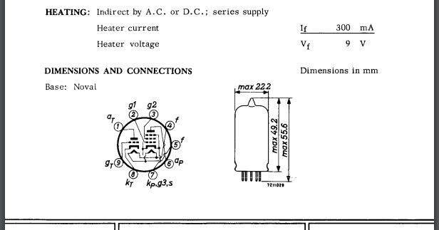 So in summary: looks like a PCF200 would probably do the trick. The heater needs 8.5V which would probably work on 6.3V. There is an ECF200 which is the 6.3V heater version but the B10B base is a bit obscure and I can't see one with chassis mounting holes. So I'll probably stick with the tubes I've got and just try and squeeze them all in. |
| |
|
|
|
|
|
Jul 21, 2023 15:55:08 GMT
|
A quick last-minute tinker. First, the mounting holes in the variable capacitor are all tapped 6BA. I will need to mount this upside down in the top of the case and that means the screws will be visible on the top. I don't have any stainless countersunk 6BA screws and I don't want to have to find an obscure size Imperial Allen key if (it even exists). So, can you force an M3 tap through a 6BA thread and open it up to M3? Yes, yes you can. Test run on a hole that won't be used: 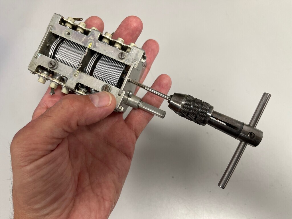 Then the real thing:  And try it out with an actual M3 screw:  Good. Now for a play with the internal layout. I need 4 jacks in total for: sine, square and sawtooth outputs; and the voltage control input. I want them in the top and they need to be at the front or down the side to be accessible. On the front panel there needs to be a knob for the variable capacitor and a second one for the decade selector rotary switch. The variable capacitor takes up a whole chunk of the internal space and if it's in the front it will get in the way of everything. So I've opted to put it at the back and extend the shaft to the front with one of these: 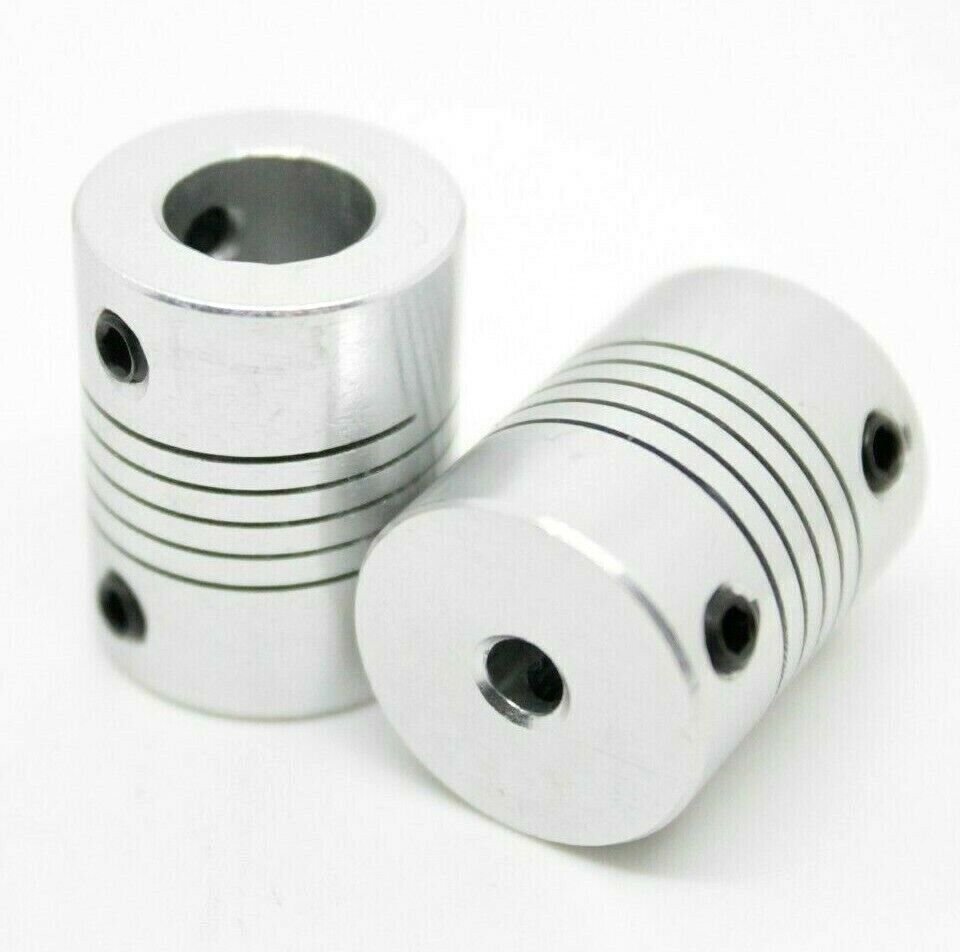 Conveniently, the jack sockets are just the right depth to clear the shaft if I bend the pins over. That gives me roughly the following options for internal layout: 1. Sockets grouped in the middle, valves down the side.  Main issue with this is the leads are going to have to go over the valves to the next module along and I'll have to keep reaching over or across them every time I change anything. Not ideal. 2. Sockets grouped on the right, valves down the middle. 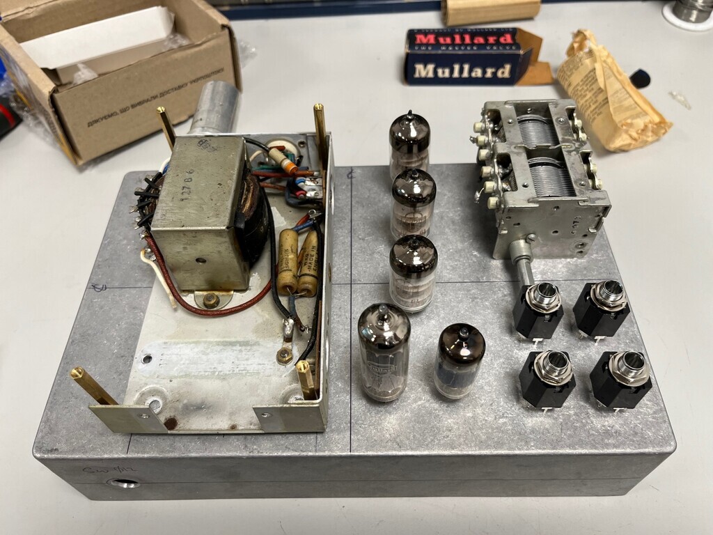 Would probably work. May have some clearance issues with the rotary switch touching the valve bases and the shaft coupling on the sockets. 3. Sockets along the front, valves grouped in the middle. 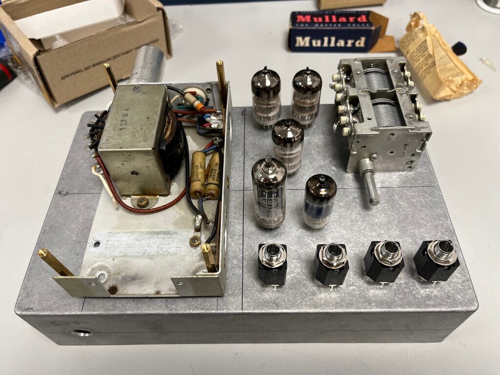 Best place to have the sockets really. The valves are quite close together but I think it's workable. Plenty of clearance for the shaft coupling. The decade switch could either go on the front or in that empty space on the top, front right. It would work well three from a circuit wiring perspective. I think this is close to where everything should go. |
| |
|
|
|
|
|
|
|
Well credit to the eBay seller. I contacted them to say it wasn’t as described and I wasn’t happy, and they just stuck another identical board in the post. This one is complete with its connector: 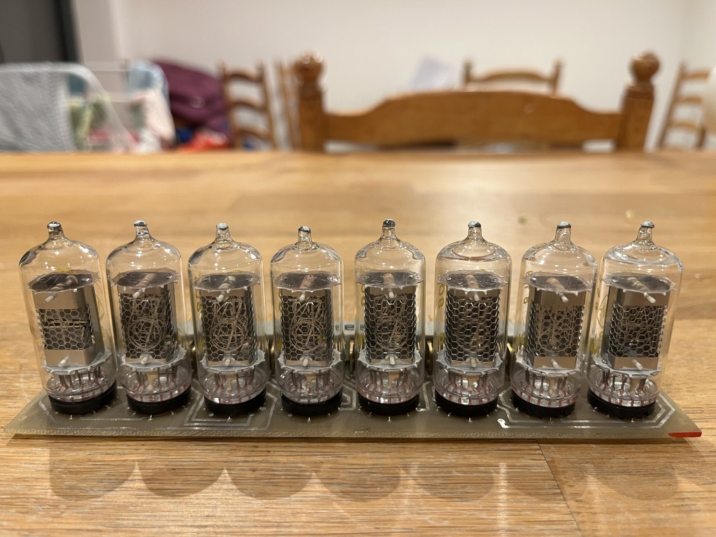  So I have the six tubes I need plus a few spares, and a couple of symbol tubes to play with. Literally no idea if any of them work so I guess I’ve got some lunchtime fun next week with life-threatening DC voltages! Z5730M are the number tubes. 13mm character height, displays 0-9. Z5810M (far right) displays A, F, H, S, V, Omega, Hz, s. Z5800M (second from right) displays T, G, M, k, m, µ, n, p. Z5710M (far left) displays +, -, sinewave. |
| |
|
|
|
|
|
Jul 24, 2023 12:00:02 GMT
|
They light! I used a little buck converter board I've got to go from 12V DC to 200V DC with a 47k resistor in series to limit the current to a few mA. Positive side goes on the anode on pin 13 and the negative lights the numbers as it's touched on the other pins (cathodes):  (200V DC on croc clips wasn’t scary at all) These boards probably came out of a Soviet-era East German multimeter. The tubes are German made. Left hand tube displays +, - and ~, then there are five number tubes, then two symbol tubes for milli, micro, kilo etc and V, F, A etc. I’ve got two of them now, so ten number tubes in total. I want six for the nixie clock, so there are a few extra to play with. Number tube data: www.tube-tester.com/sites/nixie/data/z5730m/z5730m.htmThe sine wave is cool but doesn’t photograph well: 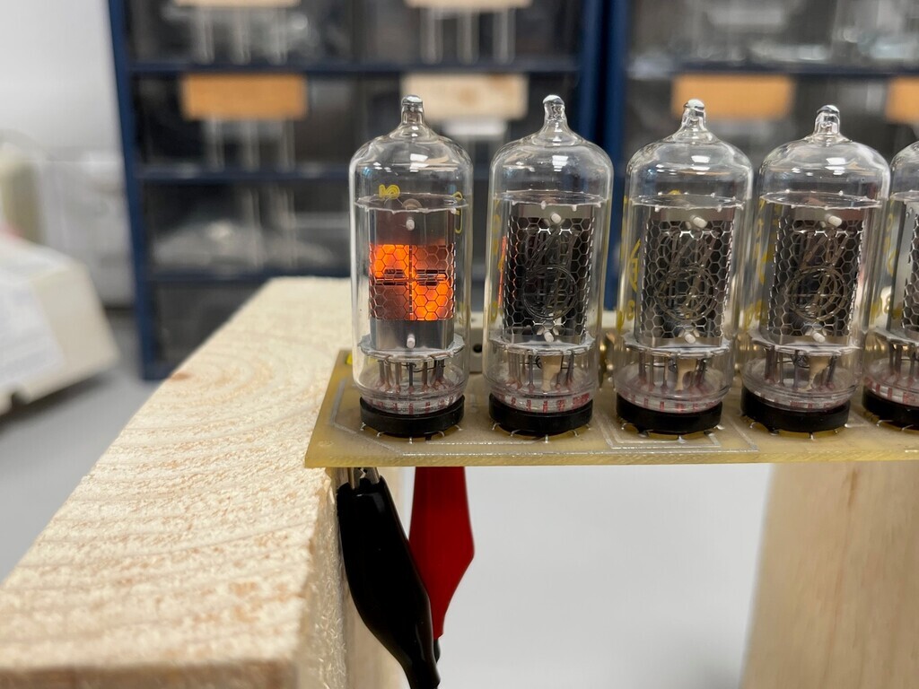 The original board is a bit bashed, up but the nixies on both of them match and display like they’ve barely been used. One of the tubes on the original board doesn't appear to display the 2, but that's no problem. The second board is in great condition and has like an old style million-pin computer connector. I’m probably going to swap one of the tubes over to that one so I’ve got 6 number tubes in a row and use a 12V universal nixie clock board to drive it straight through the connector. |
| |
Last Edit: Jul 24, 2023 20:54:43 GMT by Jonny69
|
|
|
|
|
|
|
Jul 28, 2023 14:45:43 GMT
|
Not much progress due to lunchtime mouseproofing antics in my other thread, but I have got the hole cut out for the IEC socket. 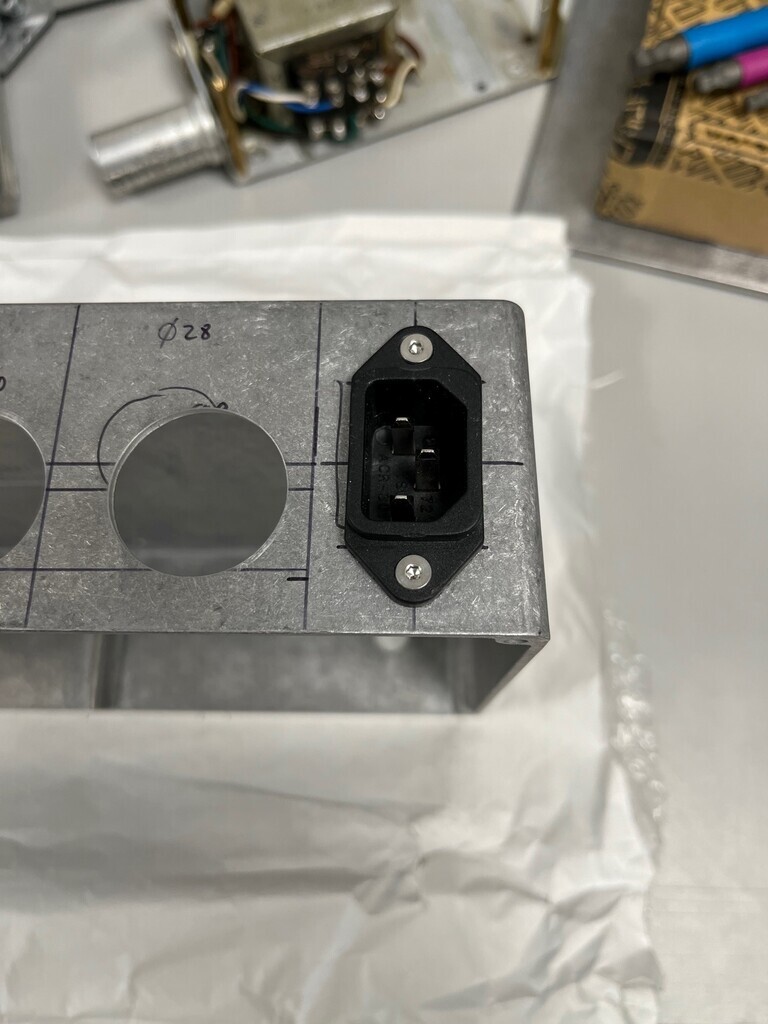 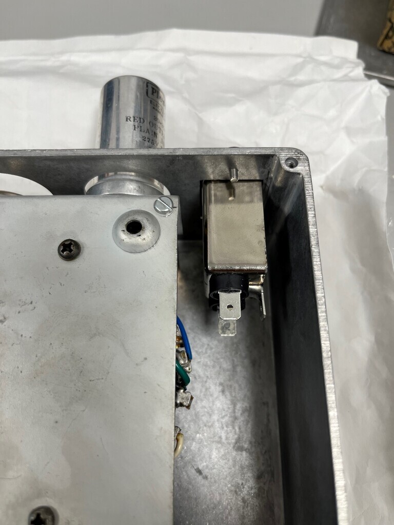 |
| |
|
|
|
|
|
|
|
I got my shaft coupling. For my 6mm shaft I cut down a 1,000,000,000,000mm stainless M6 bolt to 80mm. I didn't know I had any that long either. This is where I'm at: 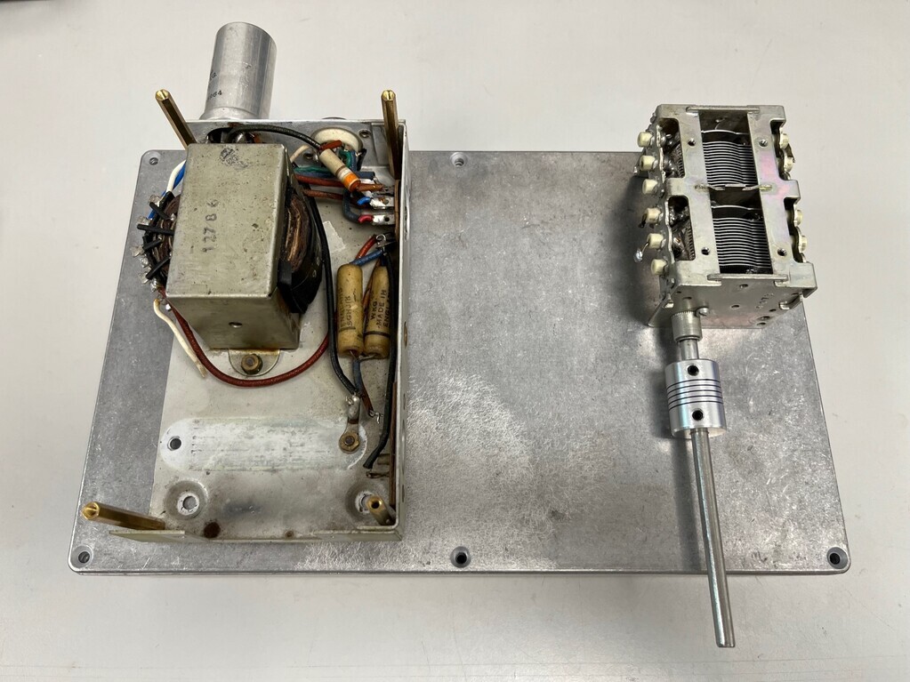 So that needs to pass through the front panel and I don't want it making a grating scraping sensation against the bare aluminium and there's a chance it might affect the capacitance if it does that. So I need a bush. The front panel isn't vertical though, it's actually at 2° or 3°. So I actually need a slightly squiffy bush, so that the shaft goes through horizontally. I opted to 3D print something and I'll get it slung on the printer next time it's on. It's basically a top hat bush with the back face angled at 2° and 3° like this and I'll print one of each:  Whichever one fits best will get used. |
| |
|
|
|
|
|
Aug 16, 2023 20:22:32 GMT
|
Bit the bullet and got stuck in with the drill, committing to some component positions. I’d love to do this with my usual positioning ratios of threes and fours, but there are a couple of components that won’t allow this. Main one is the capacitor as that can only really go in one place so that everything else will fit. That’s up in the corner as close to the sides as it’ll go without shorting the connections: 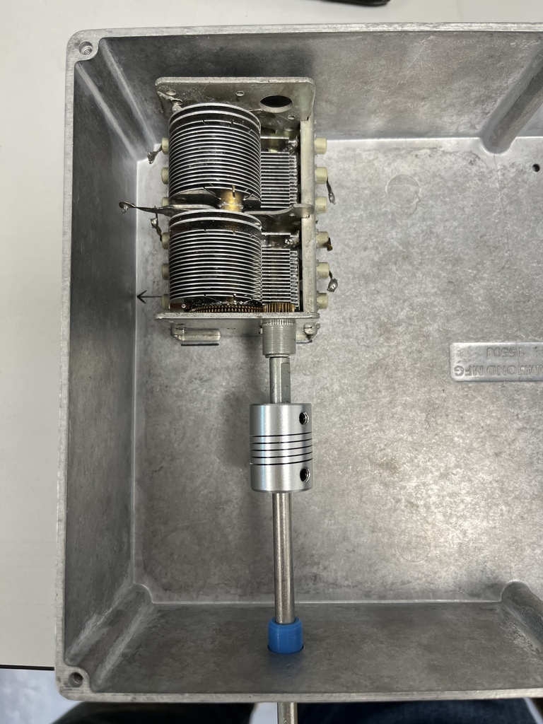 Measuring for the hole position for the shaft was a bit of a pig and I ended up a couple of mm out, but that’s why I opted for the flexible coupling over a rigid one because it allows for a bit of misalignment. Next was where I actually went wrong, in a place I really didn’t want to: 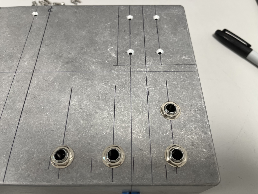 First I mis-measured the positions of the jack sockets because I divided the space by 5 instead of 4. I often do this, getting mixed up by the number of divisions, so I simply corrected my divisions and re-marked the case. However, when I extended the lines up to the hole positions, I marked up from one of the wrong ones and got stuck in with the drill without checking. Classic case of not measuring twice before cutting once, so the end two jack sockets are in the wrong place. I have a couple of plans how to fix it and I’ll make sure I’m more careful with the valve holes. |
| |
Last Edit: Aug 17, 2023 18:55:56 GMT by Jonny69
|
|
|
|
|
Aug 17, 2023 17:55:59 GMT
|
It’s a 6mm balls-up. I had this idea that I might slot the right-hand socket holes 3mm to the left and the middle ones 1.5mm to the right and you probably wouldn’t notice the mis-centred spacing, but I got overwhelmed with OCD when I marked out the gap it was quite big and I could actually do with keeping that 1.5mm for clearance between the jack socket leads and the capacitor shaft. So instead I set it up on the pillar drill, clamped down securely so I could cleanly centre drill and re-drill the holes despite them overlapping. Result: 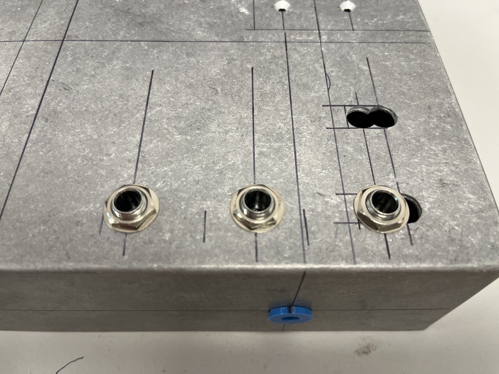 I’ll think about what I’m going to do to fill the gaps later. Drilling the valve holes is next. I need to remind myself which rotary switch I was going to use. Then I can wire this up… |
| |
|
|
93fxdl
Posted a lot
   Enter your message here...
Posts: 2,019
|
|
Aug 17, 2023 19:36:37 GMT
|
|
Use circular identification labels, or how about some brass washers to add highlights
Ttfn Glenn
|
| |
Last Edit: Aug 17, 2023 19:37:08 GMT by 93fxdl
|
|
jimi
Club Retro Rides Member
Posts: 2,220 
|
|
|
|
Use circular identification labels, or how about some brass washers to add highlights Ttfn Glenn Or even this sort of style but set sideways (with writing oriented to suit) ?  |
| |
Black is not a colour ! .... Its the absence of colour
|
|
|
|
|
|
|
Hmm, you've both given me ideas for 3D printed tags with sine, square, triangle and VCO symbols  |
| |
|
|
93fxdl
Posted a lot
   Enter your message here...
Posts: 2,019
|
|
Aug 18, 2023 10:21:06 GMT
|
|
|
| |
|
|
jimi
Club Retro Rides Member
Posts: 2,220 
|
|
Aug 18, 2023 14:14:13 GMT
|
  They are nice, would work I think 👍 |
| |
Last Edit: Aug 18, 2023 14:16:42 GMT by jimi
Black is not a colour ! .... Its the absence of colour
|
|
|
|
|
|
|
|
Yeah I’m loving the look of those. I can see those working a treat 👍
|
| |
|
|
|
|


 They are nice, would work I think 👍