|
|
|
Feb 23, 2023 12:54:11 GMT
|
Not been able to get in the lab for a few days so not been able to finish this off. Been thinking ahead how I'm going to make this sequencer thing. I want it to play a series of notes and repeat. I'm thinking of using a 555 as a metronome to keep time and I can use the output pulses as clock signals to run an octal timer. I have the MC14022 to do this. Then I have 8 outputs that I can use for separate notes as it counts round and repeats. The faster the 555 runs, the faster the notes play. That's probably the simple bit. There's probably some simple way of turning the 14022 outputs into a particular voltage, digitally. I'm going to have a crack at doing it with resistors and switches. I have 1V/octave set up on the LMNC VCO and that has a range of 5 octaves from 0V to 4V. It has 4 precisions resistors that click it from 0V, 1V, 2V, 3V and 4V. According to the internet, if I divide each volt equally by 12 I should get 12 semitones which should give me all the notes. I should be able to do that with a ladder of resistors on rotary switches. I reckon I can do this with a 2-pole 5-position rotary switch to do the octaves and a 1-pole 12-position switch to do the notes. The potential divider for the octaves will go around 5 positions of the 2-pole switch (4 resistors), one pole counts up while the other pole counts down, and the 12 semitone notes will run around the 12 positions of the single pole switch. They go on the two pole connections of the 2-pole 5-position switch, then theoretically they should switch up and down the octaves in the potential divider when the 2-pole 5-position rotary switch is turned. Only real issue is the number of components - 8 lots of 12 notes is 96 goddamn precision resistors for the notes, plus 4 for each pole of the octave switches and an extra if I use a 5V regulator. So that's another 5 x 2 x 8 = 80 resistors. Then 8 octave switches, 8 note switches, 8 voltage regulators, 8 op amps for buffers, dual gang pot for 555 speed control, 17 selector knobs. Just that lot alone is going to be quite expensive. Obvs I need to test this first. I'm going to build a hokey single note player. I've got a 2-pole 6-position rotary switch that I can use. I checked the stash and I've got a vintage wafer switch (expensive) with a 12-position wafer I can use. I reckon I've got 12x 10k resistors and 10x 120k resistors for the octaves and a 7805 5V regulator. Nothing will be very well in tune but that's kind of the idea. It'll make a good drone controller later. Maybe. 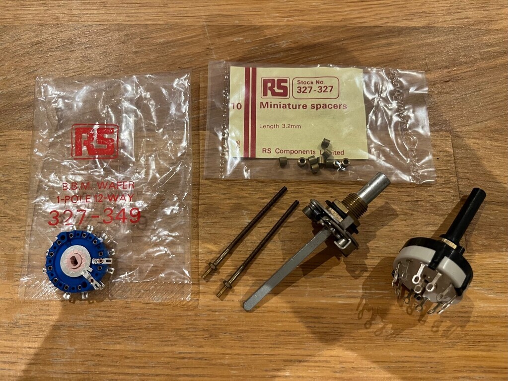 |
| |
|
|
|
|
jimi
Club Retro Rides Member
Posts: 2,232 
|
|
Feb 23, 2023 19:48:18 GMT
|
Brill 👌 wafer switches and discrete components, the proper old school way of doing things, chuck in a relay or two and your all the way.   |
| |
Black is not a colour ! .... Its the absence of colour
|
|
|
|
|
Feb 23, 2023 20:00:56 GMT
|
Brill 👌 wafer switches and discrete components, the proper old school way of doing things, chuck in a relay or two and your all the way.   And then the top secret bit is to use one of those 8 LED panels you sent me (which arrived, by the way) for each note so it counts along in a line. Don’t tell the rest of the forum I’m planning to do this. The only hitch might be the amount of power they need, because I haven’t worked out how to get enough +/-12 V into everything yet. |
| |
|
|
jimi
Club Retro Rides Member
Posts: 2,232 
|
|
Feb 23, 2023 20:13:02 GMT
|
Brill 👌 wafer switches and discrete components, the proper old school way of doing things, chuck in a relay or two and your all the way.   And then the top secret bit is to use one of those 8 LED panels you sent me (which arrived, by the way) for each note so it counts along in a line. Don’t tell the rest of the forum I’m planning to do this. The only hitch might be the amount of power they need, because I haven’t worked out how to get enough +/-12 V into everything yet. Sssshhhh  sounds great, look forward to seeing the end result.  |
| |
Black is not a colour ! .... Its the absence of colour
|
|
jimi
Club Retro Rides Member
Posts: 2,232 
|
|
Feb 23, 2023 20:46:57 GMT
|
I found the data sheet for those modules, in case you don't have it I've added to my website downloads area here LINKY |
| |
Black is not a colour ! .... Its the absence of colour
|
|
|
|
|
Feb 24, 2023 17:00:52 GMT
|
^ Excellent - cheers. I've run out of time to progress this any further this week, but the good news is these jack leads turned up. This means I can connect some things up properly next week and make some funny noises. Looks like I've got enough resistors to start the hokey noter. Getting excited now! 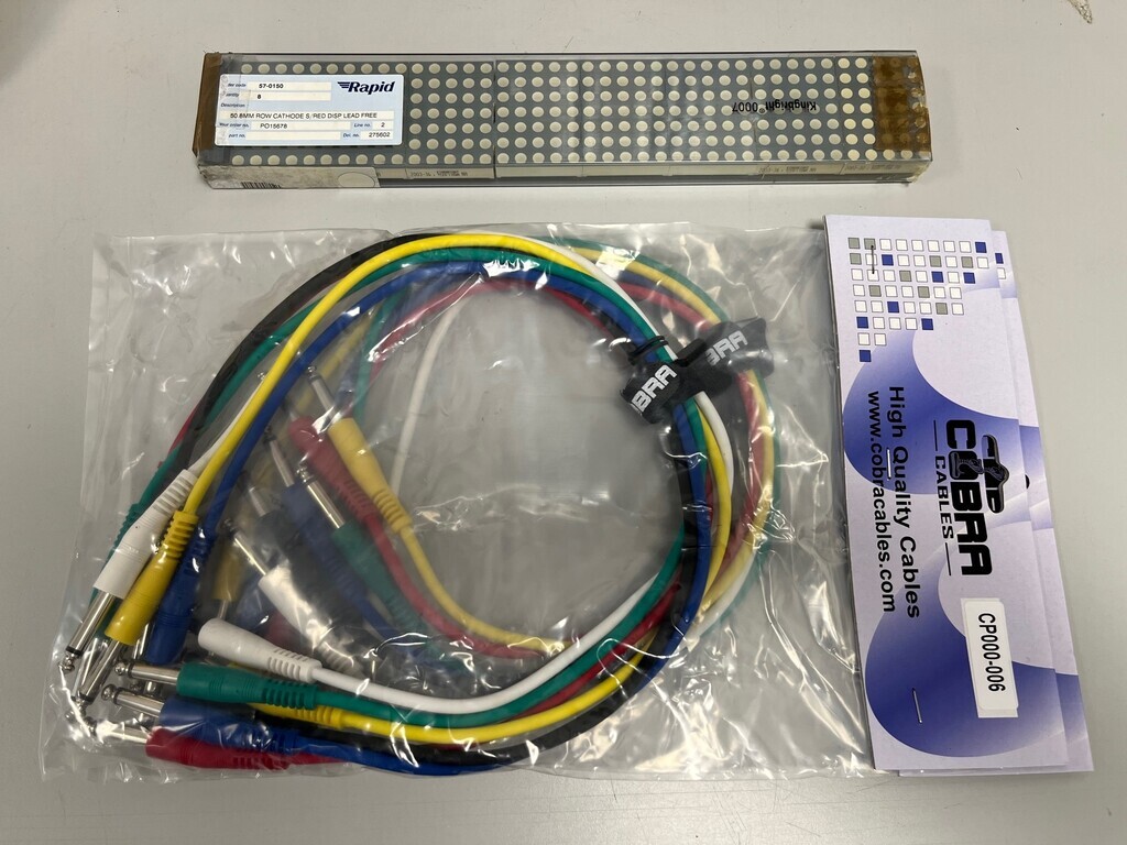 |
| |
|
|
|
|
|
Feb 27, 2023 16:12:46 GMT
|
Wired up the IO panel to the headphone jack and added some flying leads to connect to the RCA jacks once the panel is painted. Mounted it up on the panel to test and it worked first time. Relief. 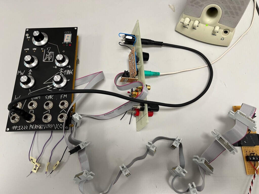 The ribbon cable with all the connectors is to distribute power connections for multiple modules. The black jack lead takes the output from the VCO to the IO panel input. IO panel drops the signal to something the speakers can use. Top left knob on the VCO selects the octave, upper right knob tunes up and down 6 semitones. Using the square wave output the upper left knob controls the pulse width, so you can make a sort of phaser sound with it while running up and down the notes. I think that officially means I've patched my first synth. Next job is to play with some control voltages and see what they do. |
| |
|
|
|
|
|
|
|
I breadboarded the hokey noter. Idea being I can stick some voltages into the VCO without committing to soldering anything permanently.  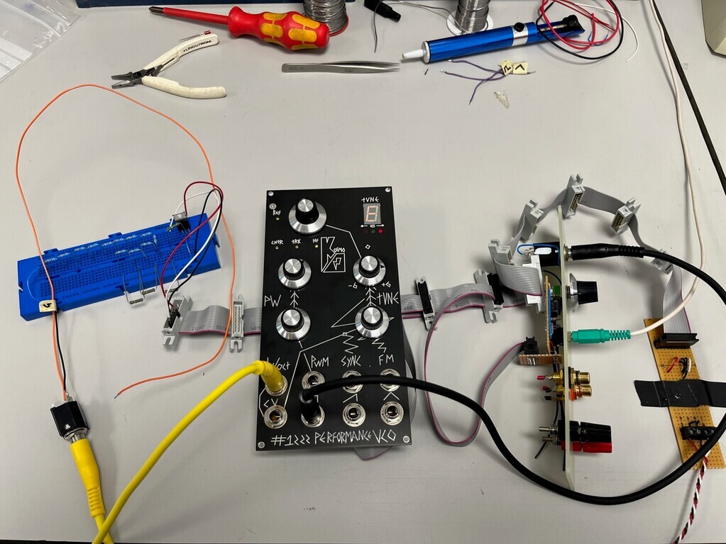 And I'm glad I did, because it didn't do what I thought it would do. I started with a 5V regulator and made up a potential divider of 5 lots of 120k Ohm resistors in series. That gives 6 voltage points of 0V, 1V, 2V, 3V, 4V and 5V. Should be one octave between them, so between 1V and 2V, the 120k resistor was made up of a chain of 12 10k resistors in series to make up the 12 semitones in an octave. Ran out of space on the breadboard, of course, so had to loop back on myself a bit to fit it on. I then stuck a jack lead in the 1V/Oct socket and on the breadboard connected it 0V with a flying lead to touch on any of the voltages. They weren't really notes and I didn't really get 1V per octave; it was closer to 2V per octave if my ears are right and felt a bit more logarithmic than linear. And the 0V point didn't play the bottom octave on the VCA, it was one octave up, so I re-arranged the breadboard to put the 12 10k resistors between 0V and 1V. Measuring the resistors, they're not going to play accurate notes, but they should at least play something close that sounds out of tune. So either I haven't understood how 1V per octave works or I've badly tuned the VCO or I've soldered something up wrong. At this point I'm not sure and some further investigation is needed. |
| |
Last Edit: Mar 3, 2023 9:58:02 GMT by Jonny69
|
|
jonomisfit
Club Retro Rides Member
Posts: 1,789
Club RR Member Number: 49
|
|
|
|
|
I'm enjoying this. Make me want to try build one.... although not the trouble shooting..
|
| |
|
|
|
|
|
|
|
I'm enjoying this. Make me want to try build one.... although not the trouble shooting.. Good stuff! It’s definitely keeping my brain working! |
| |
|
|
|
|
|
|
|
|
|
Wow, 3 1/2 months have passed. I've been thinking about this so-called Version 2 of the amp. The current situation is that the power transformer is undersized for this amp. I'm pulling a bit too much current out of it on the HT which makes it get too hot. The high current demand pulls the HT voltage down then the additional smoothing drops the voltage further, all of which means I'm not getting the most out of the amplifier. So I've been thinking about incorporating that big transformer I found. It's a bit too big by itself, but once I've added a rectifier tube, smoothing and that 10H choke, it should drop the voltage 50V or so. I really like those cast aluminium Hammond enclosures, but I think the ones I've used as chassis so far are the biggest ones they do in that range. I could do with seeing if I can realistically fit everything on before I start cutting a new chassis up. So out with the CAD... 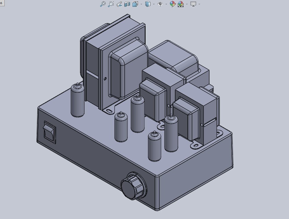 I can't fit the choke on the top, there's simply not enough surface area without sacrificing the way the amp looks. I can actually hide it at the back on an upturned smaller 1590T chassis which I'm currently using as one of the transformer covers. From the back it could look something like this: 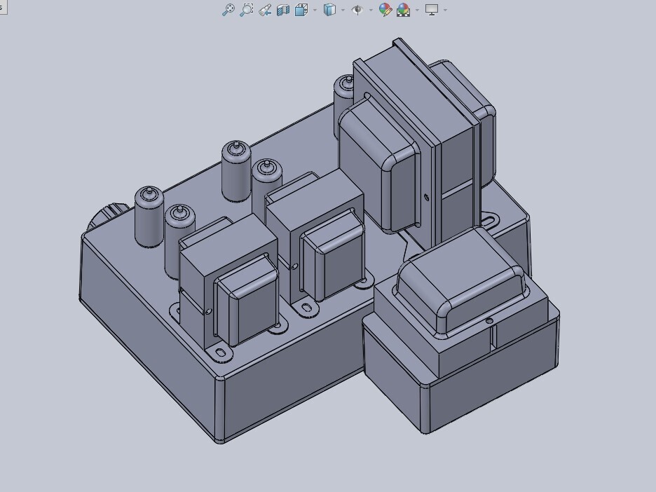 An alternative might be to have the big power transformer at the back, but I quite like the idea that you probably won't be able to see the choke because it's satin black and hidden at the back. Visually, from the front, the amp will look smaller than it actually is. Rough weights: Power transformer: 3.5kg Choke: 1.5kg Output transformer: 1.3kg x2 Hammond 1550J chassis: 1.03kg Hammond 1590T chassis: 0.29kg Plus valves etc, estimated total around 10kg. Heavy but not excessive. |
| |
|
|
|
|
|
|
|
I thought I'd resurrect this since I'm updating my valve amp and this will potentially allow me a second chance to kill myself with high voltages. I sort-off stopped because of spiralling costs and nothing much to show for it. I'm a little over £300 in at this point, which only really includes the LMNC modules, and I need to add quite a bit more before I have anything useful to play with. The only bit that 'works' so far is the LMNC VCO and that doesn't really do much by itself because it (ideally) needs a voltage source of some description to make it generate notes and then filters if I want to make interesting noises. First I ought to finish the valve oscillator, since I started buying bits for it. Since I put down my initial ideas for this, I realised that square and sawtooth waves are more useful for a synth than sine waves. I also learned about generating those on a valve circuit by tapping into different points of the timing system. That's covered in the Wireless World articles in the this post, so I'm planning to build the circuit as-is but I'll allow space to tap into the timing circuit and allow space to stick in another valve if I need it. This could end up doubling-up as a valve function generator. So, I've bought a thing to progress the project: a power supply: 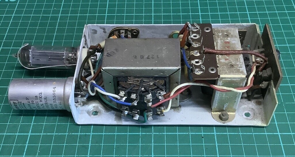 If it looks familiar you'd be right, because it's exactly the same as the one I used in my pre-amp. The only difference is this one still has its smoothing choke. No idea what it's off, but it's from the same eBay parts robber seller and I really liked the compact, integrated form. It makes it easy to work with and almost what you might call modular, and it fits nicely in the metal Hammond enclosures I like to use. Next thing I bought a transformer for the VCF. You can see it in the top right of the circuit on the output of the EF86 and it forms part of a feedback loop: 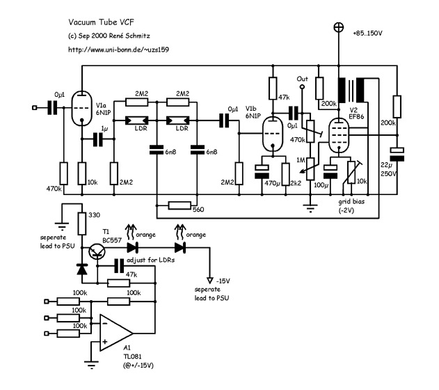 Its function isn't completely clear. I would have thought you could use a resistor and decoupling capacitor here, but the author has stated: I could have used the plate of the pentode directly as the feedback signal, but I included a transformer, to provide a low impedance. (Its nothing special, I used a 230V to 24V 2W power transformer. The other option would have been another tube. The 200k at V2s plate is used to provide damping to the tuned circuit which the transformers inductance forms with the parasitic capacitances. Adjust it to your needs.)So I've gone with what they did and I can fiddle with it later. I found a little 24V 2W on eBay which should do the trick:  Next up is to try and decide what type of LDRs are needed. I'm really not familiar with using them so it might be a bit of trial and error to get them working. I'm also wondering if I can swap out the voltage summing op-amp at the bottom of the circuit with an ECC83 driving a couple of those luminophore lamps I've got (or even the MTH-90 lamps or IN-3 lamps I tested at the bottom of this post). That'll be something for later though - one thing at a time... |
| |
Last Edit: Jun 8, 2023 12:47:15 GMT by Jonny69
|
|
|
|
|
|
|
I've picked up a mixed pack of 5mm LDRs which should have the values I need. I got two each of these: Maximum voltage: 150VDC Maximum Wattage: 90mW Operating temp: -30'C to +70'C Spectral peak: 540nm Response time: 30ms (Rise), 30ms (Down) Resistance: @10 Lux GL5506 2-5k Ohm GL5516 5-10k Ohm GL5528 8-20k Ohm GL5537 18-50k Ohm GL5539 30-90k Ohm GL5547 3-15k Ohm GL5549 45-100k Ohm Dark Resistance: GL5506 0.2M Ohm GL5516 0.5M Ohm GL5528 1M Ohm GL5537 2M Ohm GL5539 5M Ohm GL5547 20M Ohm GL5549 10M Ohm The circuit diagram says orange LEDs but the LDR spectral peak is 540nm, which is a yellowy green. Not sure how that is going to affect things or if I should maybe just use green LEDs. Soon find out. I figure, also, I probably want to use basic, old-fashioned LEDs and not modern bright ones. The circuit is from 2000 and bright LEDs weren't really a thing then. 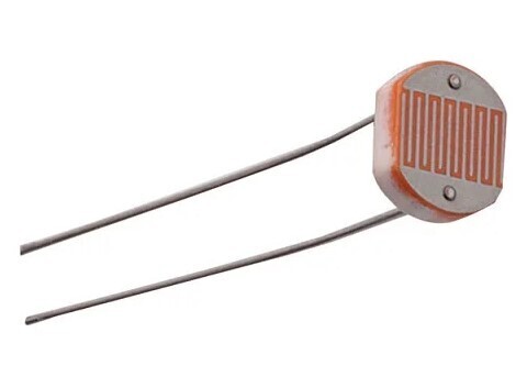 |
| |
|
|
|
|
|
|
|
The PSU arrived and is indeed identical to the other one, bar the choke. That meant all I needed to do was quickly check all the wires went to the same places, check everything was grounded to the chassis, no shorts, no broken wires, then I was happy to attach some mains and test it. First without the rectifier valve to check for sparks, smoke and explosions, then with the valve and repeat. Here it is up and running: 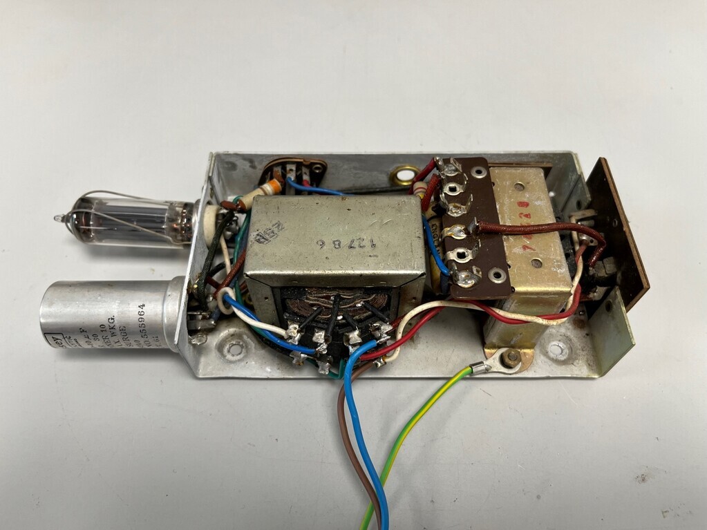 Healthy 290V DC on the HT and the Mullard EZ80 rectifier valve glowing away nicely: 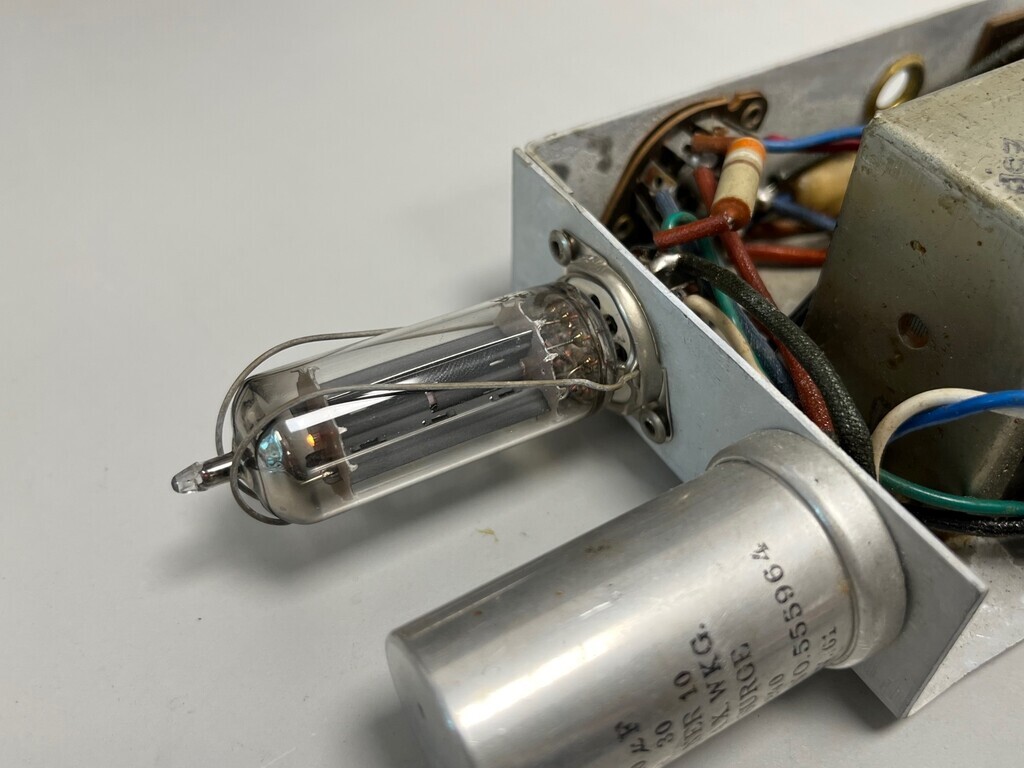 The other transformery thing that I thought was a choke isn't a choke, because it's got two windings. It's not connected to anything on the PSU. One winding goes to two wires on the B9A header and the other is connected to the RCA jack on the end panel labelled EX LS: 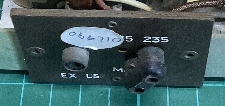 Can't decide what that means. EX maybe means External? LS maybe Line Speaker, Loudspeaker, Line Source? The outer winding to the B9A header measures 535 Ohms DC resistance and has a 5.8k resistor and 0.001uF cap in parallel with it. The inner winding to the RCA jack measures 0.4 Ohms. I think that rules out the RCA jack as an audio input, because the impedance is too low. I put 5V rms on the 535 Ohm winding at various frequencies which resulted in the following voltages on the RCA winding: 106mV at 50hz 109mV at 100hz 110mV at 200hz 111mV at 500hz 111mV at 1khz 110mV at 2khz 106mV at 5khz 94mV at 10khz 66mV at 20khz 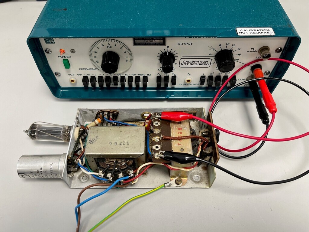 So it's about 50:1 ratio. The fact that it keeps going up to about 10khz means it could be a low quality audio transformer, but the input impedance seems a bit low for a valve output transformer. 100V line speaker maybe? Answers on a postcard to the usual address. |
| |
Last Edit: Jun 9, 2023 13:38:42 GMT by Jonny69
|
|
|
|
|
|
|
Ok, pretty confident it's an audio output transformer for a small single valve. I measured the taps on one of my RS 3W output transformers which are about the same physical size and have multiple impedance taps on both the primary and secondary windings. The resistances match an 8-9k primary and 3-4 ohm secondary and the input and output voltages also match. 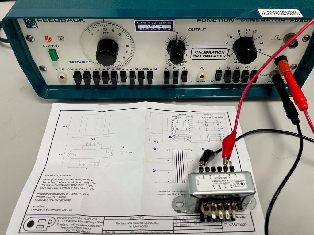 |
| |
|
|
|
|
|
Jun 20, 2023 10:40:34 GMT
|
For the valve oscillator I've been looking at the design parameters in the Wireless World article to adapt it to my needs. The example they worked through was for a fixed frequency of 50hz with a 22V output. I want a variable frequency and ideally I'd like to use the big variable capacitor I've got so I can sweep through a range of frequencies. The timing circuit is the R1, C1 and R2, C2 pairs on the far left: 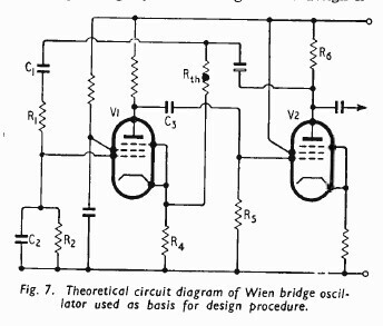 R1 and R2 are the same value, and C1 and C2 are the same value. My variable capacitor is a 2x 525pF so it will slot in where C1 and C2 go and therefore give me a variable frequency. So that it's not just a random range of frequencies, I can calculate a value for R1 and R2 to set the lower frequency and add two more capacitors across C1 and C2 to limit the upper frequency. If I don't add the additional capacitors, the upper end of the frequencies will be extremely high and heavily squashed up at the top end of the scale. To make all this easier, I put the equations into an Excel sheet so I could easily fiddle with the values: 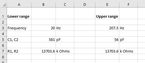 I aimed for a 20-200hz range to start with (to see if it worked) and that showed I needed 13.7M resistors for the bottom end and 56pF capacitors to limit the top end. To then get higher frequencies, all I need to do is switch resistors R1 and R2 by a factor of 10 smaller to go up a decade, so 1.37M for 200-2000hz, 137K for 2000-20000hz etc. That'll be done with resistors on a wafer switch to switch in the new values. I can alter the range to do 10-100, 100-1000, 1000-10000 by doubling the resistor values etc etc. That bit is quite simple. The next bit I wanted to do was to try and adapt the circuit to use 2x EF86 pentodes instead of an EF86 for V1 and an EF91 for V2. This simply would have meant all the holes I drill are the same size, all the valves I buy are the same, all the valve bases are the same, same size spacers and so on. For V1, they have done all the hard work already because it's already worked out for an EF86, but I followed the process through using an EF86 datasheet just to be sure I was doing it correctly. I got slightly different values, but only different enough that I put it down to maybe some slight differences in the datasheet they may have been looking at compared to the one I've got. The thermistor is something which doesn't have a lot of information covered online. I think it's there because the circuit starts to resonate from zero and the amplitude basically increases to a point where it needs regulating. The thermistor is where this happens and it alters the voltage in the feedback circuit to regulate the amplitude. My numbers called for a thermistor value of 4.4k with a dissipated power of about 42mW; a 4.7k 50mW thermistor seems to be a common part so I'm 80% (ie mostly) confident that this part of the circuit will work with a bit of tweaking. I think this means that either R4 or Rth will need a trim pot in series. Where I started to trip up was selecting resistor values for V2. There's a little inconsistency between the two worked examples which I need to go back through the article and check, but either way the values required lay outside the resistor values in the tables on the datasheet. This itself isn't a problem because the valve doesn't have to operate between strict limits, so I very roughly extrapolated the values on Excel graphs to extend the values for Ia, Ra (R6) and Rk: 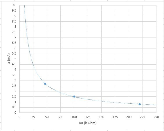 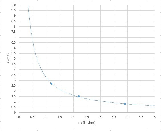 However, because the relationship between the gain and feedback from V2 back into the circuit is quite critical, this is where I lost my confidence in my selected values and I'll need to re-read the article before I'm happy an EF86 will work here. I think I may need to build this circuit as-is, initially, and work on changing the valves and output voltage later. So off the back of that, I've ordered an EF91 to use for V2 (which wasn't expensive) and I can use the Wireless World values for now. The EF91 is another miniature valve with a B7G base, but the key difference between the EF91 and the 6AS6 is that the EF91 can take 250V whereas the 6AS6 can only take 180V. As I mentioned before, 180V is a bit more challenging to get down to from 300V than 250V, so the EF91 is preferable to the 6AS6 from that perspective.  |
| |
Last Edit: Jun 20, 2023 10:41:22 GMT by Jonny69
|
|
|
|
|
Jun 22, 2023 10:29:01 GMT
|
Last bit of theory and I should be able to get on with the build. For both a function generator and a synth VCO, I need a square wave and a triangle or sawtooth. I don't think the square wave will be too difficult to generate. I plan to do this by brute force by amplifying the sine wave until it clips at the top and bottom. Using an op amp, this is really easy to do. Because an op amp's open-loop amplification is essentially infinity, if you feed a sine wave into the input with no negative feedback, a square wave appears at the output. With a valve you won't get this because the amplification factor of something like an ECC83 is around 90, but I think if I do it in two stages I'll get something which is mostly square. Two things I need to consider. Firstly is that a valve does not clip symmetrically. It tends to flatten one half of the waveform and stretch the other, which is essentially that second-order harmonic distortion which gives valves that 'valve sound'. Example shown here from the Valve Wizard triode amplifying chapter: 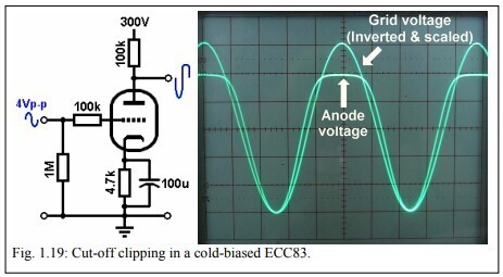 However, this is an inverting amplifier. I think if I use a high-gain dual triode valve (ECC83 or 6N2P) and brute force the clipped/distorted output of one triode into the input of the other, it will distort the waveform equally in the other direction and I should get something which tends towards an equal square wave. It will also be back in phase with the incoming sine wave. The second thing I need to consider is that valves soft-clip, which is where the square wave has slightly rounded corners. I don't think I'm too bothered by this. I think it just means it won't have such a raw square sound to it at the top end because it won't have quite as many high frequency harmonics. Next up is the triangle and/or sawtooth waveform. This is going to be more challenging to generate but I think I've found a way. Page 407 of Wireless World, August 1960, discusses the Transitron Timebase as part of its series on triggered circuits, which can be used as a generator of sawtooth voltages. I need to read up more on this, but it looks like in this example an incoming square wave pulse is used to trigger a sawtooth: 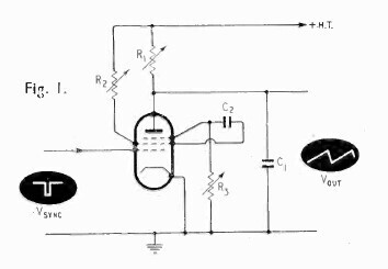 And within the timing circuit, the following waveforms can be found:  So as well as the sawtooth output, there is a triangle wave available to tap into. That is, if I've understood this correctly! The tricky bit for the sawtooth and triangle will be getting the charging and discharging to happen at a rate so that the amplitude of the sawtooth and triangle is the same at different frequencies. I might need another amplification stage to correct for this. Total valve count so far is 2x pentodes for the oscillator, 1x dual triode for the square wave, 1x pentode for the transitron circuit and possibly one more pentode or dual triode for an additional amplification stage. |
| |
|
|
|
|
|
|
|
The LDRs arrived so I had a go at seeing what they did with an old-style green LED. I figured I’d want to check a couple of these so I soldered the LED to a length of wire with a 330R resistor on one leg and heat-shrinked the legs to make it easy to handle: 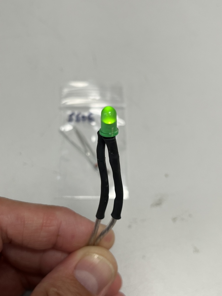 Then I could tape the LDR facing it and measure the resistance at different brightnesseses from 0-12V: 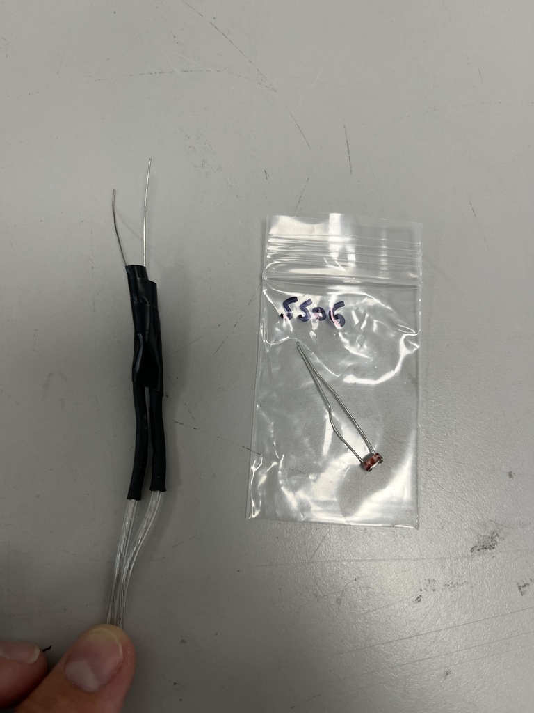 For this one I got about 1.5M when dark and about 500R when bright, so quite a decent swing. If I were to put this in the feedback loop of an amplifier, for example, it would effectively become a voltage controlled amplifier (VCA). I started marking up the case for the oscillator. The challenge with this thing is going to be fitting everything in, because the variable capacitor takes up a lot of space. 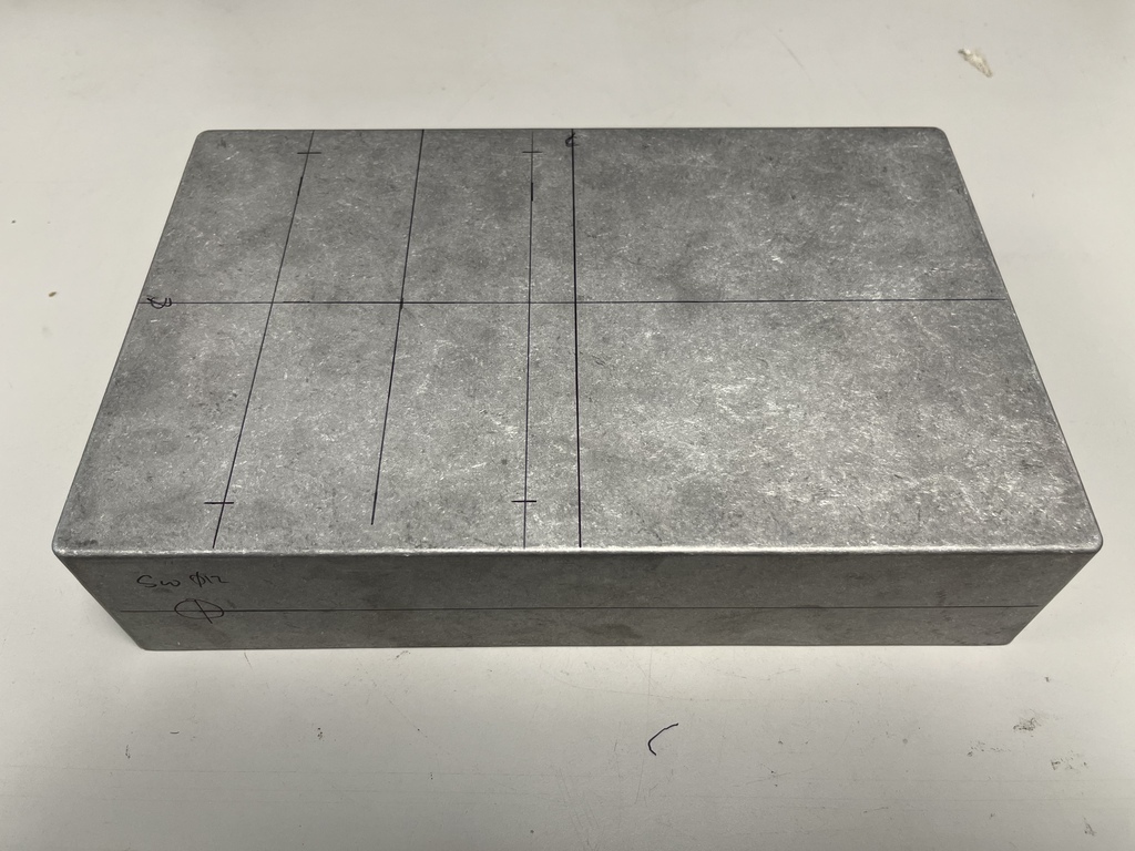 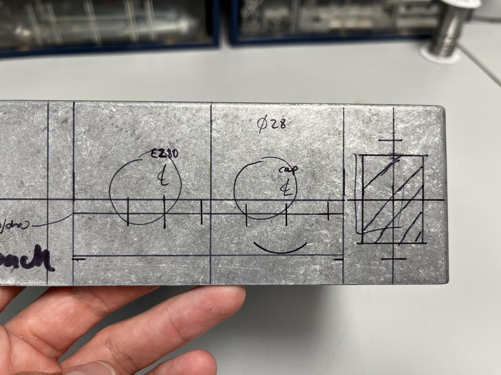 |
| |
|
|
|
|
|
Jun 28, 2023 11:50:40 GMT
|
Postie has been. First is the EF91 for the oscillator: 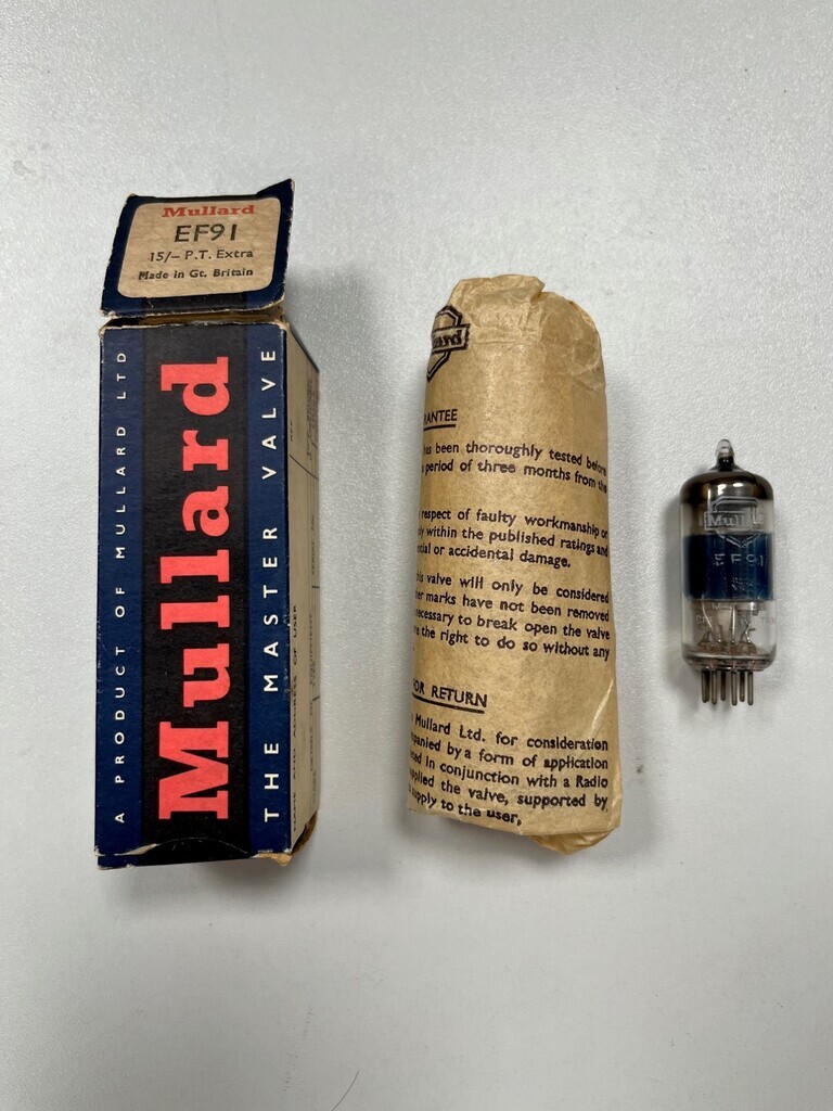 Next are some more valves, which may seem a bit random at this point:  There is method behind the madness. The oscillator is going to have its own power supply. However, if I'm going to be making a few different valve-based modules, they're going to need power too. I'm changing the power transformer in my 3W valve amp in the other thread I was going to sell on the old transformer, but it might make more sense to use it as my master power supply. Question is how to distribute the HT safely and I think I can do this with 3-pin XLR leads, female sockets in the power supply chassis and male ones in the modules. I can probably re-use the amplifier chassis (which already houses the transformer and rectification) and re-drill the valve holes to take the female XLR sockets. The male plug is shrouded so there should be no way of accidentally touching the HT. If I use metal sockets and plugs it'll also be earthed wherever there are connections. I'll run a DC heater supply with a common 0V which will be on the long pin in the XLR socket. I think that should be safe. So that means I'll need another EZ81 rectifier tube. They aren't the cheapest valves and I spotted someone selling a good looking one with a couple of other interesting-looking valves which might make a little audio project in the future. Left to right, description from r-type: DK92 miniature heptode frequency changer. Domestic long and medium wave receivers would have this as the mixer to produce a 455 kHz IF from the incoming signal. It can be used with a separate oscillator, but was probably designed as a self oscillating mixer, in the manner of other pentagrid converters. DL94 audio output pentode from Mullard was designed for use in battery portable radio receivers. Mullard describe the DL94 as a battery operated output pentode with centre tapped filament, and designed for operation with equal voltages on both screen and anode. Last one the label has rubbed off but I think it's a DK91 miniature dry battery heptode and the internally connected pins seem to confirm this. It sort of completes a set which may have been in a battery-powered radio. The DK91 is a miniature B7G dry battery heptode, it was designed for frequency changer use in battery portable radio receivers. The valve was designed for self oscillating service. Next is some B7G valve bases. These were supposed to be NOS but one of them is well used, so they'll be going back to the cheeky eBay seller: 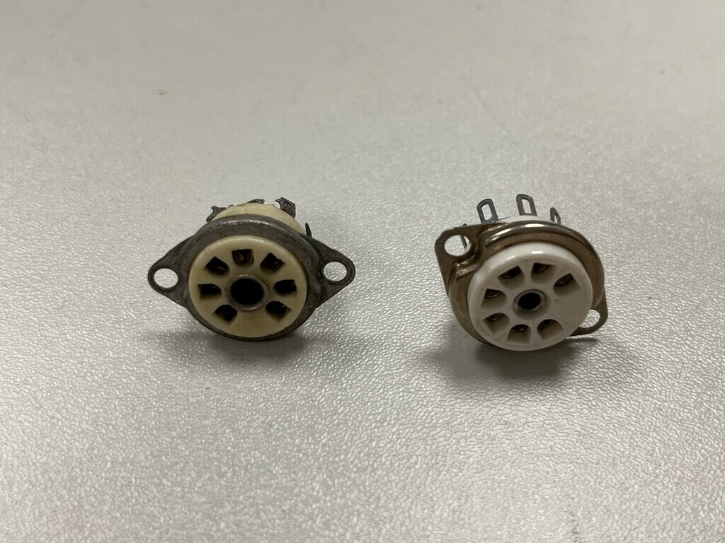  Finally, the transformer for the voltage controlled filter. It's actually quite a bit bigger than I was expecting it to be: 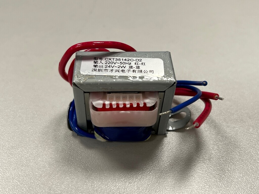 |
| |
|
|
|
|
|
|
|
I picked up some valves last night. I say some; over 200 of them...  They came from an old tech guy in his 80s who was wrapping things up and was pleased to see them go to a good home. He also made me take a box of capacitors and a replacement tube for my scope. Couldn't refuse. Probably about a third of them are of direct interest. About a third are TV valves from the 40s and 50s which I'm not sure what to do with, because I think their only use is for TV signal processing. Probably sell those ones on. About another third are radio valves. Some of the big ones are early radio valves from the 30s. Again, not sure what I can do with those. The rest are audio frequency, diodes and rectifiers which I'll want to use. I've moved some of the ones I recognise up to the top right corner but I need to catalogue what's there first, which will take a while! My kids are fascinated by these. Little boxes with mystery shiny silver glass bottles of treasure inside. |
| |
|
|
|
|


 sounds great, look forward to seeing the end result.


