|
|
|
|
|
^ That's the one - from www.nixiediy.com/ I wanted non surface mount, I didn't want to have to program a separate Arduino (though the controller is an ATMEGA328P as on an Arduino) and I wanted to be able to use my own spacing between the tubes so it could be any size. This one has onboard high voltage from 12V too, so I don't need to worry about additional power supply. Can recommend. Got it soldered up and tested at lunchtime & after work. That’s all ready now to connect up the tubes and stick the CR2032 in when I’m ready. 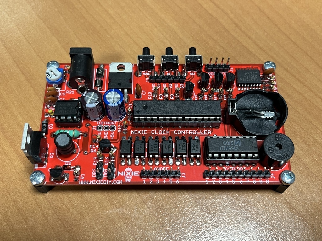 |
| |
|
|
|
|
|
|
|
Dec 11, 2023 15:42:55 GMT
|
I added the 30k dual pot with 3.3k resistors inline. That gave me a resistance range of 3.3k to 33.3k. My calculations suggested that if I used 0.47uF capacitors I'd get a frequency range of 10hz to 100hz and if I used 0.047uF capacitors I'd get a frequency range of 100hz to 1000hz. I started with the 0.47uF because a) they're bigger and I can get my fat fingers round them easier and b) because 10-100hz is easiest for me to get my brain round when viewing on a scope screen. 10-100ms, see.  I kind of wanted to see whether it would run up and down frequencies without tripping up and what the amplitude would do. Well, it does run up and down the frequencies. However, between 10hz and 100hz, at the moment it looks like there is approximate doubling in the amplitude, which isn’t great. I swapped the 0.47uF caps for 0.047uF and it’s far more consistent between 100hz and 1000hz. I’ve been doing some twiddling of the pot inline with the thermistor and I can get the output relatively stable between 100hz and 1000hz if it’s around 19-20V. It’s about 1V variation from top to bottom frequency which I think is acceptable. I wonder if the big variation below 100hz is something to do with those frequency response graphs I plotted previously. So anyway, it’s looking good at the moment. A slight aside - here's something interesting in progress. The silver coating inside the top of a valve is called the ‘getter’. It’s a substance that maintains the vacuum in the tube and it starts to disappear if a tube starts to lose its vacuum. I noticed this EF91 is losing its shine on one side, so at some point it’ll start to stop working properly and eventually fail.  |
| |
|
|
|
|
|
Dec 19, 2023 13:22:01 GMT
|
If you go back a few pages, you might remember I failed to spot that the two halves of the capacitor were not separated and were grounded by the chassis, so it wouldn’t work in the circuit. Annoyingly, I’d already drilled the case before I realised and because it’s quite a big lump it could only really go in one place and dictated the layout of everything else. That means it’s a bit too late to go back on a couple of things without shelling out on a new case and starting again from scratch. It’s not a massive issue and I made up a bracket to fit the potentiometer where the variable capacitor was originally going to go: 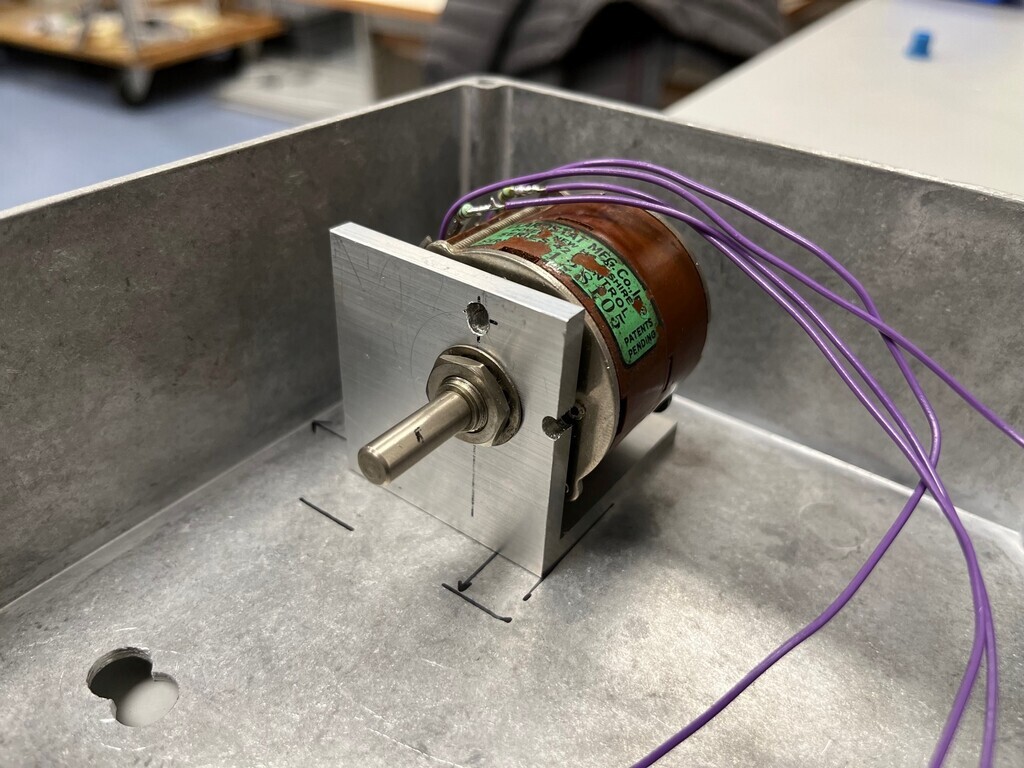 I used the mounting holes I’d drilled, but decided I’d correct the position on the front where the shaft comes through the front panel. Because of the dimensions of the variable cap, the shaft was going to come out low in the chassis and slightly offset compared to everything on the top. It would have looked a bit weird but there wasn’t really much I could do about it. So I made the bracket offset so the shaft comes out in an aesthetically better place. I’ll open the hole up on the front with a hole saw in the pillar drill and make an offset 3D-printed inset to plug the hole. Lunchtime today I decided to modify the preamp slightly with a 3.5mm jack in the back. I've been using some RCA doublers to send the signal to the VU meter, which are are huge and take up loads of space at the back. I tried some piggyback RCA leads but they weren't much better. Drilling in a 3.5mm jack was the way forwards. 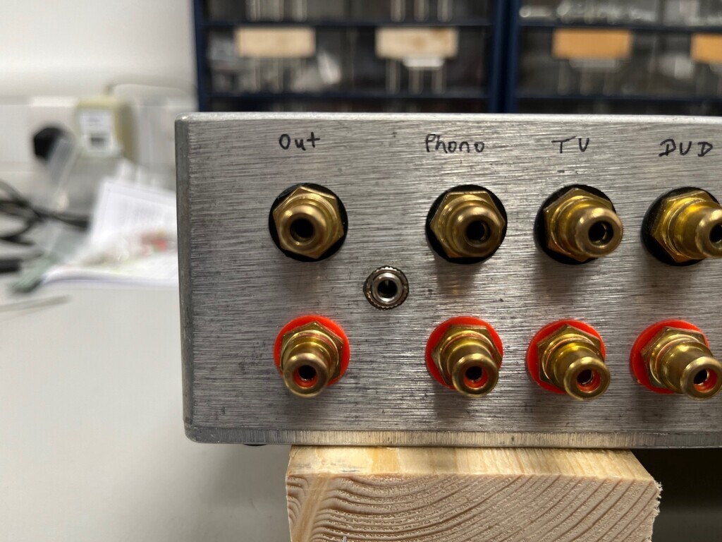 Not completely straightforward, however. The wall thickness of the case was too thick for the threaded portion of the jacks I've got. So I had to drill them slightly oversize so that the alignment slot would also go through. Drilled without checking, of course, but then found out the locking ring was smaller than the hole. Not enough thread to use a thin washer, not even shim, so I've had to bodge it a bit and bond it in place. It'll knock back out with a bit of persuasion if I need to take it out. |
| |
|
|
|
|
|
|
|
Case drilled up for valve mounting and offset bung printed and bonded into place. Rotary switch for octave selector added. The row of three valves down the middle: front two are the main oscillator with sine output; back one will be for the square wave. The two horizontal ones on the left are going to do the sawtooth. I put them like that so they’re not right next to the power supply transformer, else I couldn’t really fit them in without everything being squashed up. 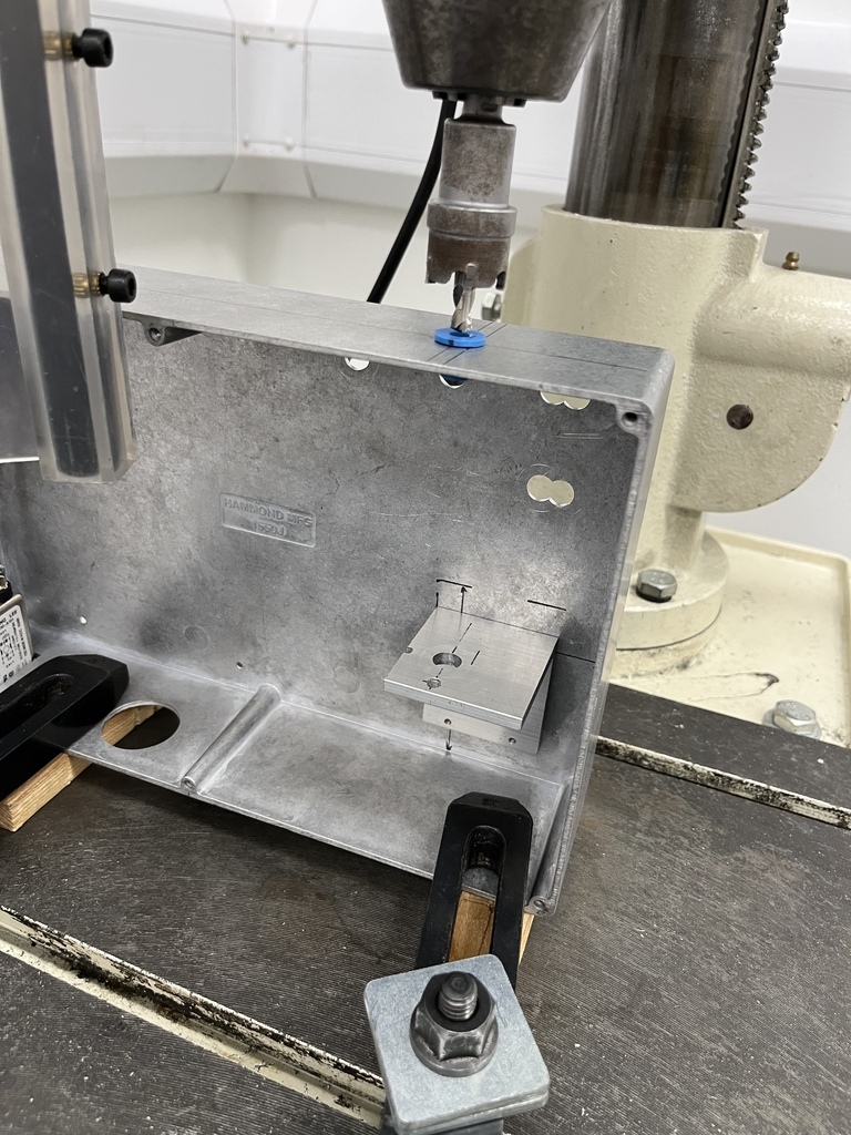 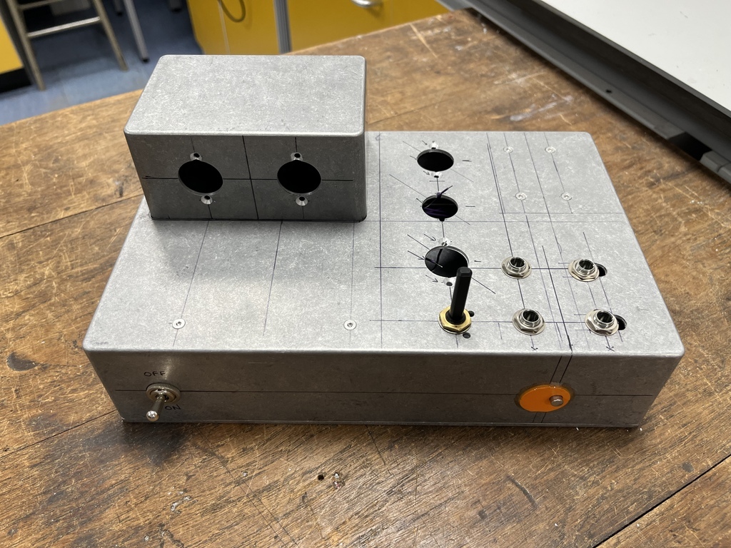 |
| |
|
|
|
|
|
Jan 22, 2024 17:52:25 GMT
|
Some synth progress. Where I left off I'd decided on a final layout and drilled the case to suit. The bit I hadn't done was worked out how the case could be assembled. I figured I'd work that one out later and it would all be fine. Well that was today so here we go. I started by putting the valve bases in and drilling a couple of holes with grommets to take wires up to the top valves. This simply took a bit of careful measuring to avoid the PSU underneath and the backs of the valve bases above: 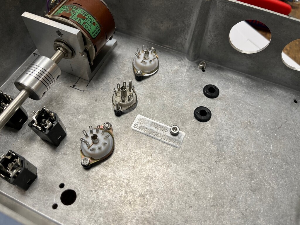 Next I decided on a sensible way to distribute the power. The PSU has to come completely out to get the top enclosure off. Hard-wiring everything would mean it would need long wires to stretch that far, so I decided to make the 0V, heater supply and HT disconnectable:  That basically meant I couldn't get to any of the screws that secure the top enclosure or the ones at the back of the PSU. I added a new bolt hole into the back of the case which secures the back of the PSU and now it all comes apart and goes back together ok. With everything in place it looks like this inside, before I start wiring everything up: 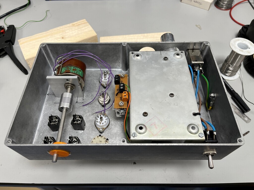 With all the hardware now in place it also means I can plug the valves in and have a look at what it's going to look like: 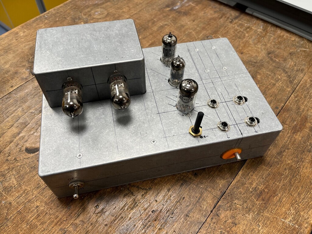 Wiring-wise, I'll start by laying down all the heater wires, then wire up the main oscillator circuit. Then I can add the square wave section onto that (valve at the back) and work on designing the sawtooth section (two horizontal valves). I'll leave provision to add the voltage control and I'm thinking about maybe having a removable capacitor pack so I can swap in different frequency ranges into the timing circuit (e.g. swap from 10-100/100-1000/1000-10,000 to 20-200/200-2000/2000-20,000 etc, or even frequencies of actual notes). That would be pretty cool. |
| |
|
|
|
|
|
Jan 25, 2024 17:27:16 GMT
|
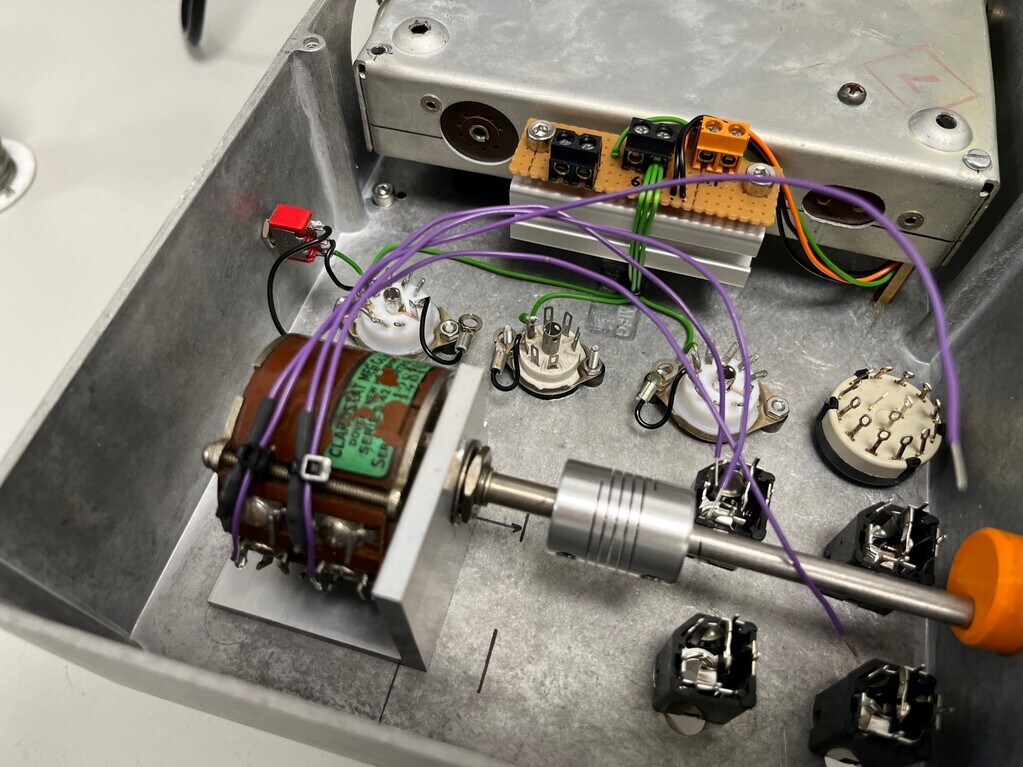 I ran the heater wires in at lunchtime. I also added a switch at the back for the rearmost valve so I can switch the heater wires between pins. This is so I can use an ECC83 dual triode or a Soviet 6N2P dual triode. Both are the same valve spec but have a slightly different heater arrangement. |
| |
|
|
|
|
|
Jan 26, 2024 17:05:52 GMT
|
I think I can feel another rabbit hole coming on. I need a small amp for upstairs and I was going to build something. Easiest way would be to use one of my many power supplies and a stereo class D module from eBay. This one would be ideal: 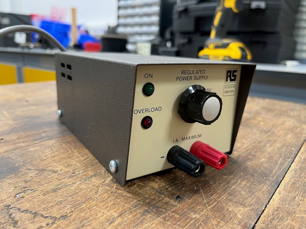 Fix it at the 15V setting and use the hole for the volume pot. Add inputs and outputs, job done. But how about a new rabbit hole instead, because that would be far too easy. I’m thinking what about something iconic like the John Linsley-Hood 1969 class A transistor amp, using new PCBs but built with vintage transistors and the Philips capacitors from my stash. Why complicate it and add loads more expense? Well, I remember MiataMark mentioned his one on the first page of this thread and I looked it up at the time. Then recently I keep getting videos about the cheap Chinese clones with fake 3055 transistors popping up on my YouTube feed. They are available pretty cheap as kits with all the components, PCBs, heatsinks and the hardware for mounting those T03 transistors. I can't buy a pair of PCBs, heatsinks and hardware individually for the price the kits, so I could just bin off the cheap components and swap in better quality ones, and basically replicate the original sound by using old transistors and capacitors. Resources: Wikipedia article on John Linsley Hood: en.wikipedia.org/wiki/John_Linsley_HoodIt says in there that it was published in Wireless World in 1969 (April 1969 issue, p. 148). ORLY? So it is: www.worldradiohistory.com/hd2/IDX-UK/Technology/Technology-All-Eras/Archive-Wireless-World-IDX/60s/Wireless-World-1969-04-IDX-75.pdf And there's a bit of early Lycos html webpage dedication here, talking about the transistors in particular: paul-kemble.tripod.com/sound3b.htmlSo to stop this getting ridiculously expensive if I do it, I could do with a power supply. About a month ago I pulled a 2x 30V @3a digital bench supply out the WEEE bin. Only one channel was working so I popped it open to see if I could fix it. It was a bit frazzled on the dead channel so I pulled off a couple of heatsinks for a pal and tossed it back in the bin. Amazingly, when I looked this morning it was still in there so I pulled it back out to recover the transformer. Here it is: 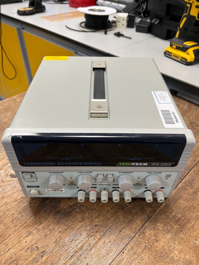 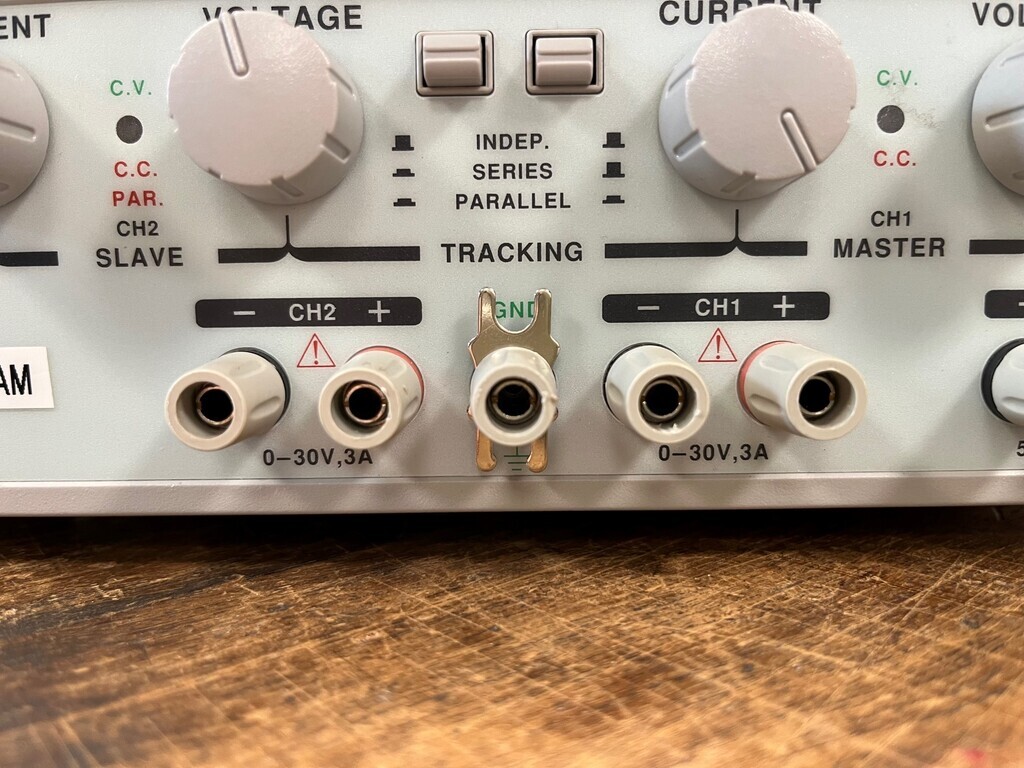 When I said it had got a bit frazzled, I mean it had cooked itself. Properly. You can see it has got a bit hot just from the circuit board: 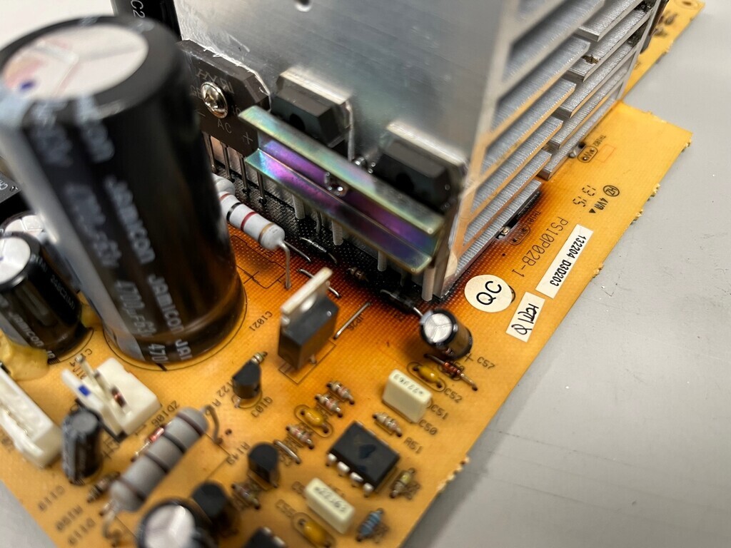  But with the heatsink pulled off I reckon it must have been smoking a bit when it popped the fuse!  This all happened because the fan had packed up and jammed. And the thermal cutout clearly worked well on that model. Anyway, with the rectifier board etc pulled out the case, this is what I'm left with: 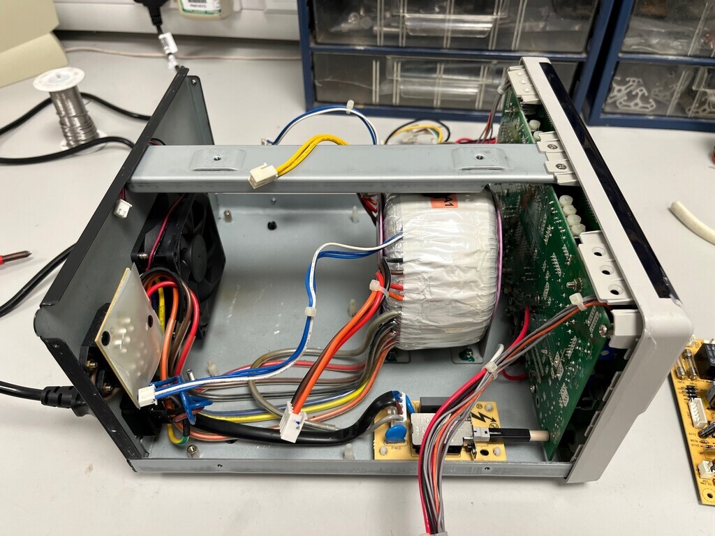 The transformer itself works fine. The two secondaries put out 33.7V AC which is ideal. I'm going to have a look at what smoothing capacitors I've got at home and if I need to recover the bridge rectifiers. There might be some fun electronics to pinch out the front panel and I might think about re-using this case. |
| |
Last Edit: Jan 27, 2024 1:03:04 GMT by Jonny69
|
|
jimi
Club Retro Rides Member
Posts: 2,219 
|
|
|
|
! there's a name I haven't heard for many years 👍 Also 3055, the PWM speed controller I built for my son's jeep used 3 x 2N3055's 😎  |
| |
Black is not a colour ! .... Its the absence of colour
|
|
93fxdl
Posted a lot
   Enter your message here...
Posts: 2,019
|
|
|
|
|
I do enjoy reading this thred, even though, on a good day i understand about 10% of it since my electronics knowledge is basic to say the least.
A bit i think i understood was the swappable capacitor packs, might it be possible to include them in the main build, with a rotary switch to change settings. If this is not possible, how about a stand alone unit with some old school type latching push buttons?
Ttfn Glenn
|
| |
|
|
|
|
|
Jan 28, 2024 19:01:40 GMT
|
I do enjoy reading this thred, even though, on a good day i understand about 10% of it since my electronics knowledge is basic to say the least. Haha, thanks! I try to keep a sensible amount of technical detail so that people who understand the electronics can see what’s going on, but not so much that everyone else can’t understand anything! A bit i think i understood was the swappable capacitor packs, might it be possible to include them in the main build, with a rotary switch to change settings. If this is not possible, how about a stand alone unit with some old school type latching push buttons? Ttfn Glenn Yeah so that’s the plan. I’ve put in a 3-way rotary switch which selects between frequency ranges of 20hz to 200hz, 200hz to 2000hz and 2000hz to 20,000hz. Later on I might want to change it so the switch ranges are 10hz to 100hz, 100hz to 1000hz and 1000hz to 10,000. To do that, I’d need to change the capacitors. So that I don’t have unsolder everything, I could just fit the capacitors on a piece of Veroboard on a PCB connector and then I can just swap them round whenever I feel. |
| |
|
|
|
|
|
|
|
Jan 31, 2024 17:00:32 GMT
|
I've got the sine wave part of the synth mostly wired up. It's just the timing circuit left (best till last, eh?) and I need some longer screws for the valve bases so I can attach the ground returns. Before I do the timing circuit I need to have a think about how I'm going to mount and wire the three pairs of capacitors through the rotary switch without ending up with a complete mess of wires, because it's getting that way already :/ 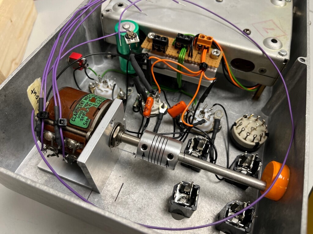 |
| |
|
|
jimi
Club Retro Rides Member
Posts: 2,219 
|
|
Jan 31, 2024 18:00:29 GMT
|
Jonny69Saw this  And immediately got a waft 🤣🤣 roasted pcb, a never to be forgotten smell 😎
|
| |
Last Edit: Jan 31, 2024 18:05:07 GMT by jimi
Black is not a colour ! .... Its the absence of colour
|
|
|
|
|
|
|
Jonny69 Saw this [pic] And immediately got a waft 🤣🤣 roasted pcb, a never to be forgotten smell 😎 Same here! I’ve not had one go that far though, it must have stank! In the post: 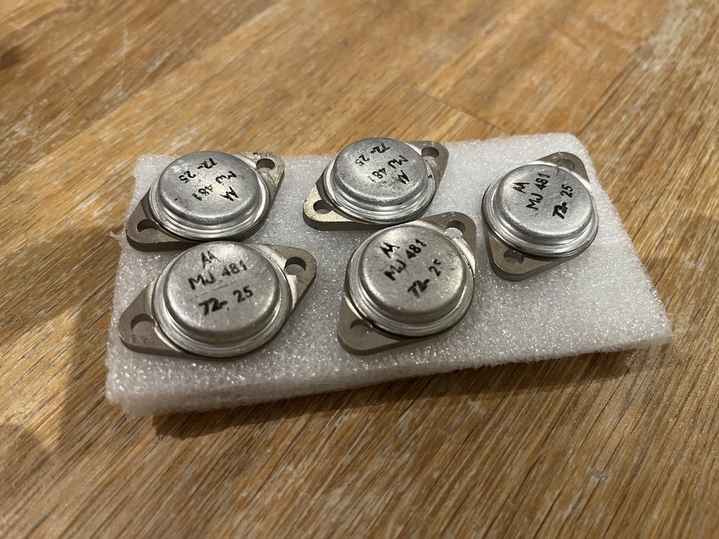 5x output transistors. Motorola MJ481, as specified in the original JLH 1969 design, dated 1972. So I guess this build is on! |
| |
|
|
|
|
|
|
|
Also on their way are some 2N697 transistors for the driver stage. I’ve specifically been looking for transistors in the older metal cans rather than the more modern plastic ones. I guess these might be 1980s or 1990s but they don’t look earlier than that. What I don’t seem to be able to find are any 2N3906 input transistors in an old-style can. The design notes mention that the most critical transistors in the design are the 697s but that the 3906s are not that important. I’ve got loads of 3906s at work because they’re just a cheap, general purpose PNP so I’ll probably use a couple of those to start with and swap them if a a couple of old 3906s or 4058s turn up.  |
| |
Last Edit: Feb 2, 2024 9:56:24 GMT by Jonny69
|
|
|
|
|
Feb 12, 2024 18:25:54 GMT
|
Been collecting some bits in the background for the amp and the synth VCO. I've bought a couple of those cheap eBay JLH 1969 amplifier kits, cheapest ones I could find, and I'll be dumping all the components and just using the PCBs and hardware. I'm wondering if they'll actually turn up because I've heard nothing from the seller. No matter, it's eBay. Capacitors, I had most of the big ones in my stash but not the 100uF and 220uF ones at high enough voltage, so I've been on eBay and found some. Will use a couple of Mullard tropical fish ones from my stash for the input coupling and apart from some 3906 transistors in metal cans, I've got pretty much everything. 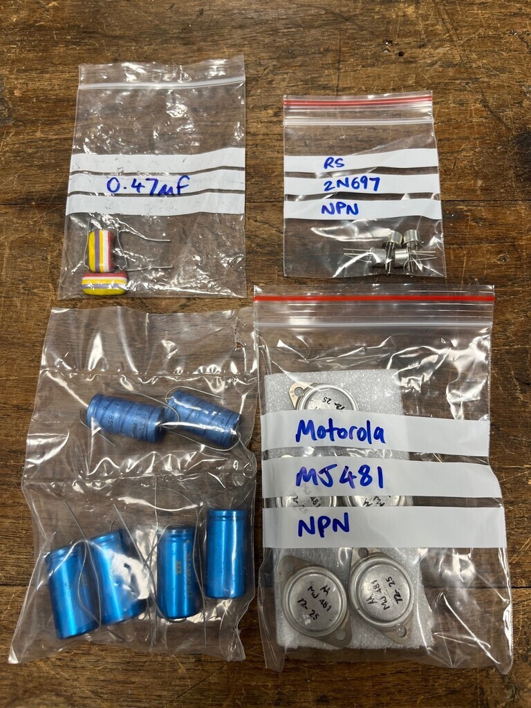  I got a used 150x100x50mm heatsink for cheap (above) which sounded quite sizeable, but once I got it in my hands it didn't actually have that much more area than my MOSFET amps have. I think it's a bit too marginal for old transistors which are less tolerant to overheating. The power supply needs some heatsinking too, so I might use it for that. Instead, I'll stack up a couple like the ones below. That's how it's done on my bench supply, so that's legit. 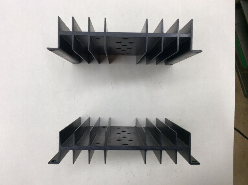 No progress on the synth yet. I needed some longer screws and kept forgetting to order them. Done that now and also ordered some engraved tags for the jack plugs etc. Suddenly realised I've got a few unfinished projects on the go. Need to prioritise... |
| |
|
|
jimi
Club Retro Rides Member
Posts: 2,219 
|
|
Feb 12, 2024 19:33:04 GMT
|
Will use a couple of Mullard tropical fish ones from my stash for the input..... ? Haven't seen that style for years, can you still get them ? As is NOS |
| |
Last Edit: Feb 12, 2024 19:33:54 GMT by jimi
Black is not a colour ! .... Its the absence of colour
|
|
|
|
|
|
|
? Haven't seen that style for years, can you still get them ? As in NOS Yes, there seems to be a fair number of them still about, which is quite surprising given their age (late 50s?). They do command a bit of a premium though, especially because they were used in old guitar amps. On that subject, that does make them a generation earlier than this amp. I’m going to see if I’ve got a couple of the later type which had a beige resin casing. I think they’re basically the same construction inside. |
| |
|
|
jimi
Club Retro Rides Member
Posts: 2,219 
|
|
Feb 13, 2024 10:21:42 GMT
|
I thought it was the other way round ? Beige ( mustard?) were 50's and the Tropical 60's ? But I may well be incorrect, it's just that I have a vague memory of the Tropical fish (also heard them called liquorice allsorts) from the late 60's when I was assembling PCB's at Beckmans  |
| |
Black is not a colour ! .... Its the absence of colour
|
|
|
|
|
Feb 15, 2024 10:37:10 GMT
|
I'm not an expert on this, but I've got a couple of generations of film caps.  Left to right is oldest to newest. Left hand one is a Mullard 'mustard' cap which I think are 1950s. Stripy one is a Mullard 'tropical fish' cap, which I think are late 50s into the 60s. Next one is the beige resin one I meant above, which I think is 70s but not 100% certain. Orange one was around in the 90s and the new ones are like a dark red colour. |
| |
|
|
jimi
Club Retro Rides Member
Posts: 2,219 
|
|
Feb 15, 2024 11:17:18 GMT
|
|
That sounds about right, I come across all those types, but the only ones I remember working with in Beckmans were the Tropical Fish and I left there around 1968, so I wouldn't have seen the beige ones, got confused with the early Mustard type. Good picture,sharpens the memory, thanks 👍
|
| |
Last Edit: Feb 15, 2024 11:18:03 GMT by jimi
Black is not a colour ! .... Its the absence of colour
|
|
|
|


