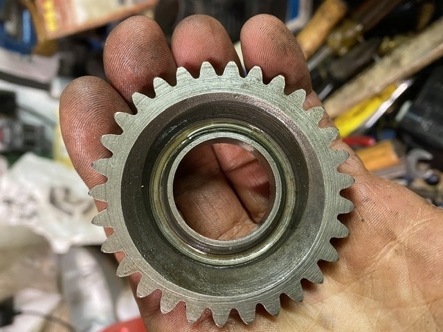
So. What on earth have I been doing all this time I hear you ask….
Well, not much Bantaming, if I’m honest, although I have ridden it a bit this year between downpours. More than I’ve ridden my modern bike actually.
It’s still too underpowered though, and no amount of looking at the pile of bits on the bench has seemed to make any of it magically put itself together, so I finally bit the bullet and started on it the other day.
BSA’s manufacturing in the 1950s was pretty much typical of the time. Stuff was made to tight tolerances in some areas, but because manpower was cheaper then, other parts were deliberately made with wide tolerances and either selectively assembled, shimmed to fit, or “fitted” in the true sense of the word by the folks that put them together.
The crank assembly is one area where the wide manufacturing tolerances are overcome by shimming the end float to acceptable levels. You start with the empty cases, and fit just the two large main bearings either side. These are normally a snug sliding fit with the crank stubs. The crank assembly is then fitted, and the two halves bolted up around it. You can then measure the endfloat with a dti. In my case it was about 0.022”.
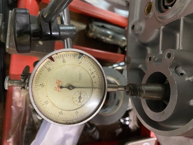
Once you have that base measure, you have to split the cases again and add shims as necessary to take this down to between 0.004” and 0.006”.
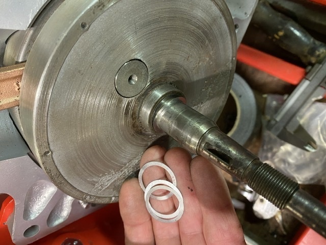
I always aim for as close to 0.004” as I can get, because the addition of a smear of Wellseal around the crankcase mating faces will add half a thou or so to the gap.
With that done, you can add the crank seals each side, and the second smaller drive side main bearing to the cases. This last bearing is always a tighter fit on the crank shaft and it, along with the seals, make measuring the endfloat really hard, so fitting them after sorting all that is definitely the way to go.
Next it’s the gearbox internals. Here they are:
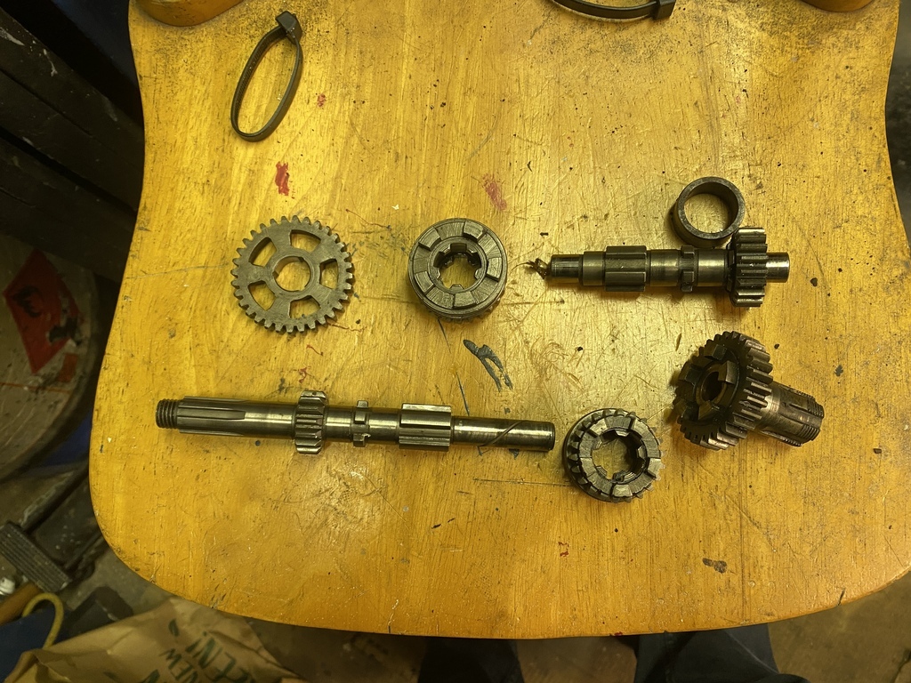
I know gearboxes are a mystery to a lot of people, so I’ll try and explain how this one works, because it’s really a simple thing.
Assembled in the cases the whole lot looks like this. The drive comes in on the left of the picture as you’re looking at it. This is the neutral position, the input shaft is turning in the direction of the arrow all the while the engine is running and the clutch is engaged, as is the large gear highlighted with the yellow marker, but the rest of the geartrain is stationary.
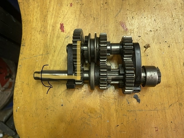
In first gear, the sliding gears are pushed towards the clutch which engages a set of dogs on the layshaft sliding gear into corresponding slots in that big idler, locking it to the layshaft. Drive then passes along the layshaft and into the output gear, which runs concentric to the mainshaft on the right. The sliding gear on the mainshaft is not locked to it in this position.
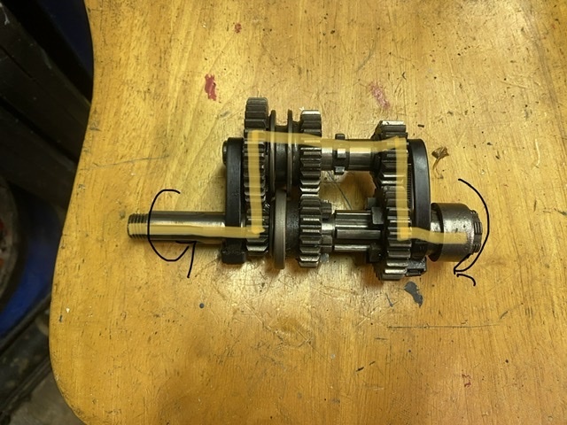
Second gear is obtained by sliding the gear pair to the right, through neutral, to a point where both sliding gears are locked to their respective shafts. In this position, the drive passes from the mainshaft to the layshaft through the two sliding gears, then back to the output gear.
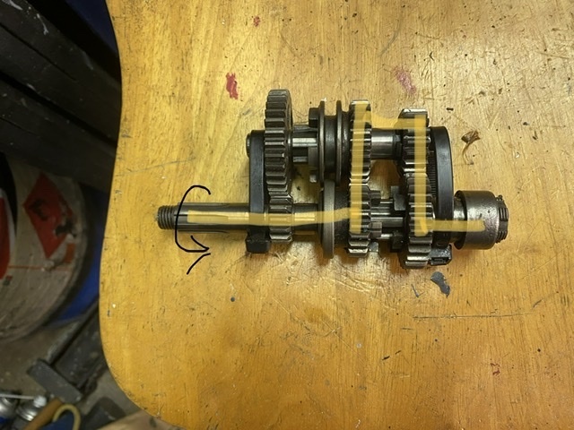
Finally, top gear is obtained by sliding the gear pair fully to the left, where the layshaft gear is free on its shaft, and the mainshaft one is locked to it’s one, with its dogs engaged in the slots in the back of the output gear. Effectively making the whole mainshaft assembly one piece and the output ratio 1:1 with the input.
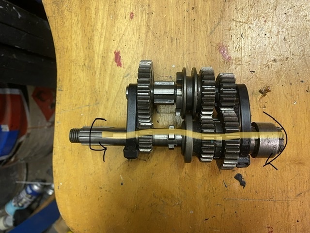
Moviing the sliding gear is done with a simple swinging selector mechanism, with a positive stop for each position provided by a spring loaded detent. It’s pushed back and forth by a fairly crude sprung ratchet.
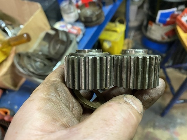
This picture shows the standard layshaft gear and output sleeve gear next to the closer ratio later items I have fitted.
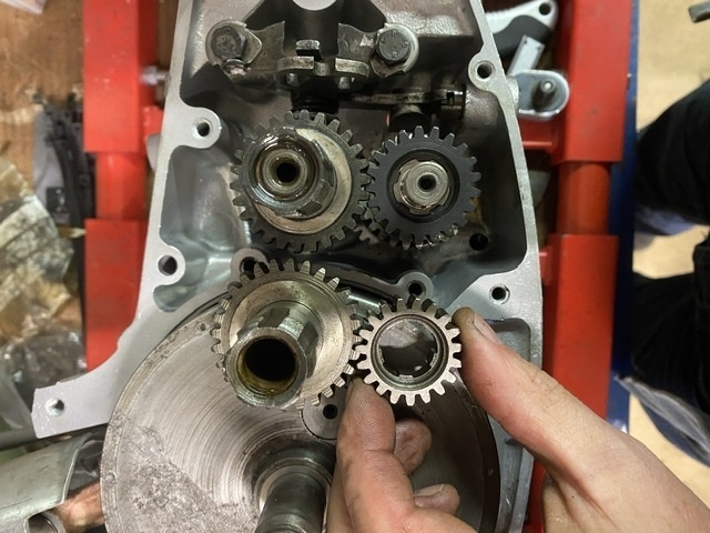
Getting that lot in is relatively simple. The four speed setup is basically the same in its operation, but there’s two sets of sliding gears and a more complicated selector mechanism.
Anyway, the next step is to close up the cases.
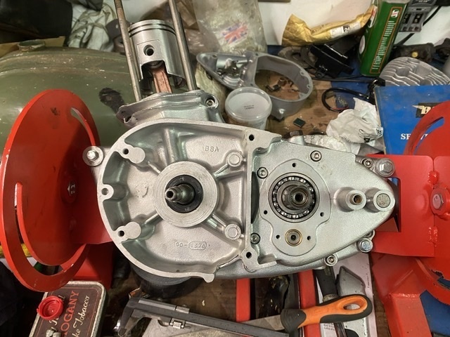
With the dowels and and all the case screws torqued up, and the crank and gearbox checked to see they both still turn freely, the gearbox output seal holder can go on next. This is a bit of a lashup on early machines, and is often a source of leaks. Still, as last as the gearbox is kept topped up, the chain never runs dry. 🤣
I found that as soon as I snugged up the mounting screws though, things got too tight and the gearbox mainshaft began to bind. This turned out to be down to the pattern gasket in the kit. The output bearing simply floats in the left hand case. There’s nothing to locate it side to side other than the mainshaft one side and the seal backing plate the other. The supplied gasket was paper thin, about 0.002”, and it meant that the bearing and outposts sleeve gear were getting forced into the mainshaft. I measured the remains of the original gasket and it was much thicker at about 0.008”. So I got some decent gasket paper of the right thickness and made a new one. This sorted the binding issue.
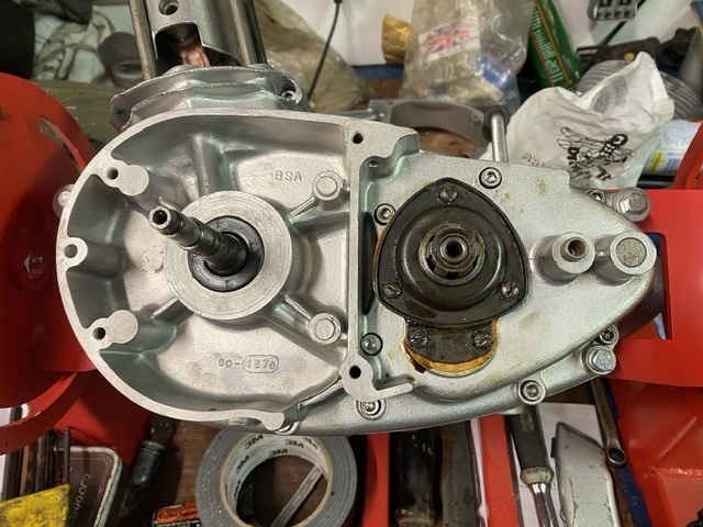
At this point, it’s important to make sure all three gears, and neutral, can be selected easily. If they can’t, then you need to find out why before you go any further. Remember, it’s a constant mesh gearbox, and relies on both the input and output shafts rotating and firm operation of the change lever.
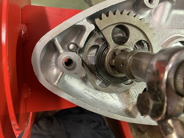
That’s the main cases done, so the next step is the kickstart quadrant. This is spring loaded. You have to put between one and one-and-a-half turns of tension on it. The spring should be wound tight enough that it’s smaller in diameter than the anti rattle shim next to it, but not so tight that it binds on itself when fully rotated. So, tighter than this:
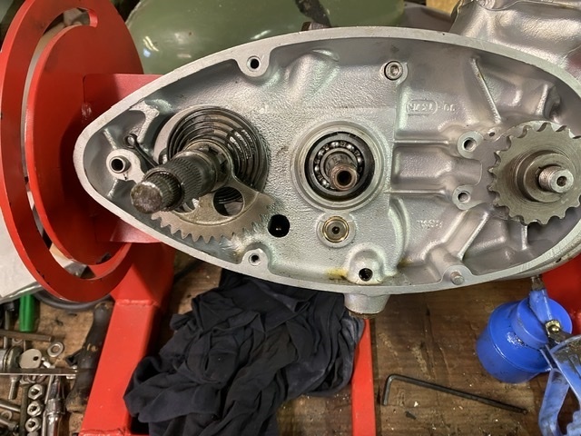
About like this is ideal:
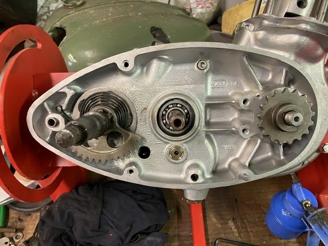
As long as you can still see space between the spring spiral when the quadrant is fully rotated. If this binds then the spring will not last long in service and changing it means stripping the whole clutch out.
Next, the clutch and primary drive. Bantam clutches come in two flavours. Early ones have three friction plates which are fine for the 125 and 150 engines, and generally give no bother with the lower powered versions of the 175, but don’t stand up to much abuse. The baskets for both types are made of solid unobtanium, and have been hard to find in decent condition for years. Secondhand ones do turn up, usually for silly money. I have a small collection of “used but useable” bits that I have rumbled through. I’ve only one early type and, although the basket is useable, it’s the one from the donor engine I stripped last year that had sat full of water, and a couple of the teeth on the primary sprocket were badly pitted.
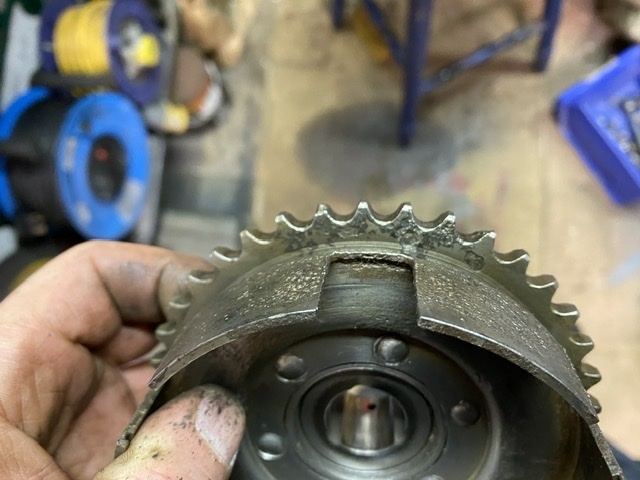
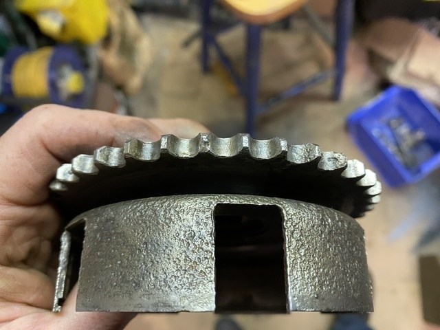
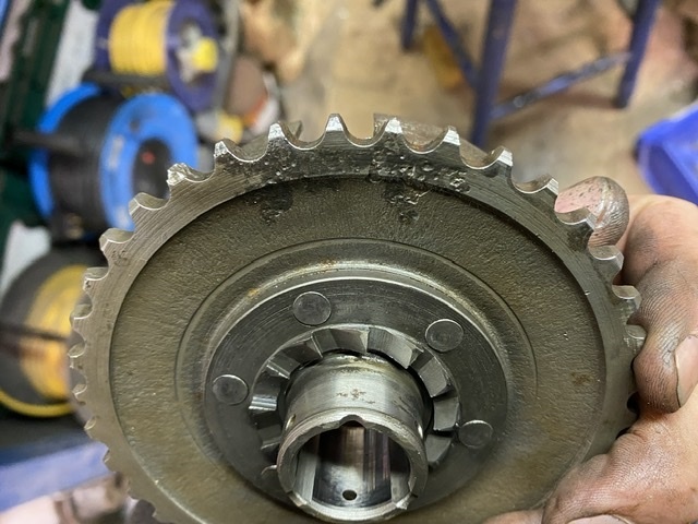
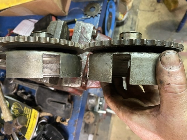
I think, given the chain drives on multiple teeth simultaneously, I could probably have got away with using it and, given that I’m not going to be riding massive distances on it, it might well have lasted indefinitely. However I do have a much better, later, four plate clutch basket. These are fitted to the last 14 bhp 175s and are a worthwhile upgrade. You can see the deeper basket here with them sat side by side:
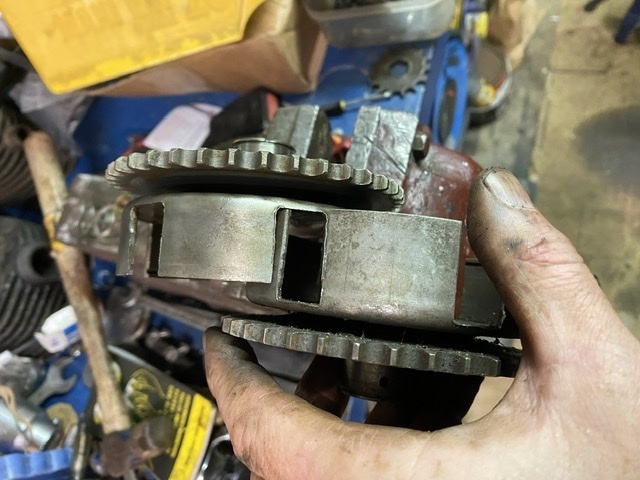
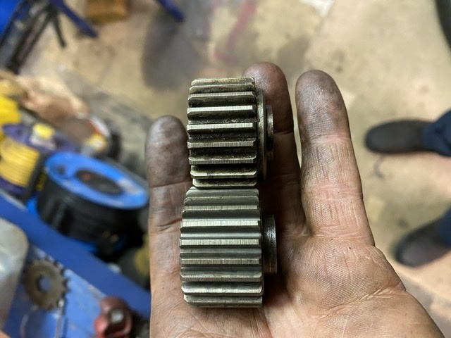
The centre drive gear is similarly deeper:
There’s another subtle difference. The early clutches run on a phosphor bronze top hat bush, with a matching pb thrust washer. Most of the later ones use a simple steel sleeve and thinner bush, and a pair of Torrington races to take the thrust loads. Conveniently, they’re interchangeable, but you do need the right drive gear to go with the thrust washer type. D10 clutches use the earlier type of bush with the later clutch, and I had a suitable centre, so that’s what I used. Late Torrington type on the right, plain bush type on the left.
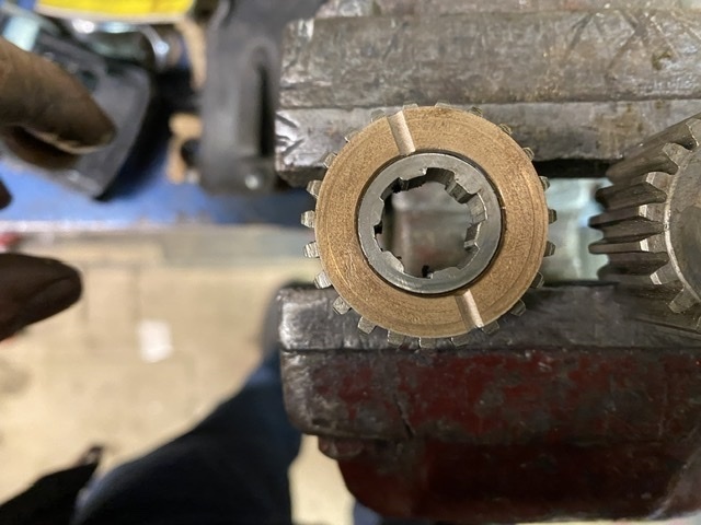
This is what the bush looks like on the wrong centre. It clearly shows the mismatch. If you looked from the side you’d see the bush is too thin as well, with the centre poking out by a mm or so.
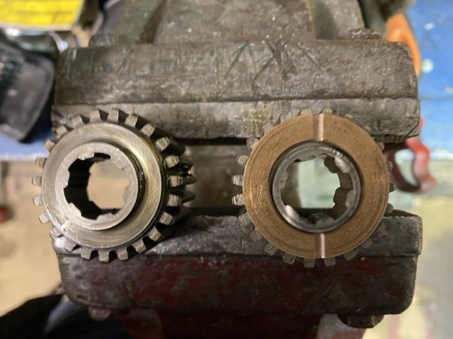
And this is how it should look:
I could have used the later type along with the Torrington races, but I’ve only got one set and I want to use them on the other engine.
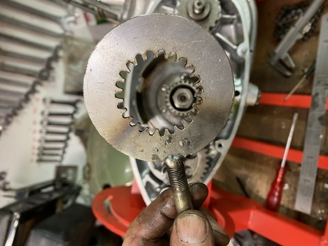
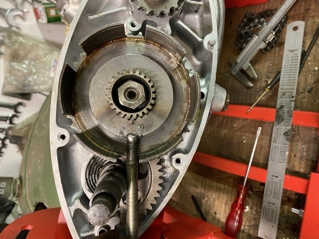
With the clutch in place, I used this tool I made years ago from an old clutch friction plate to lock the gearbox shaft and torque the centre nut up.
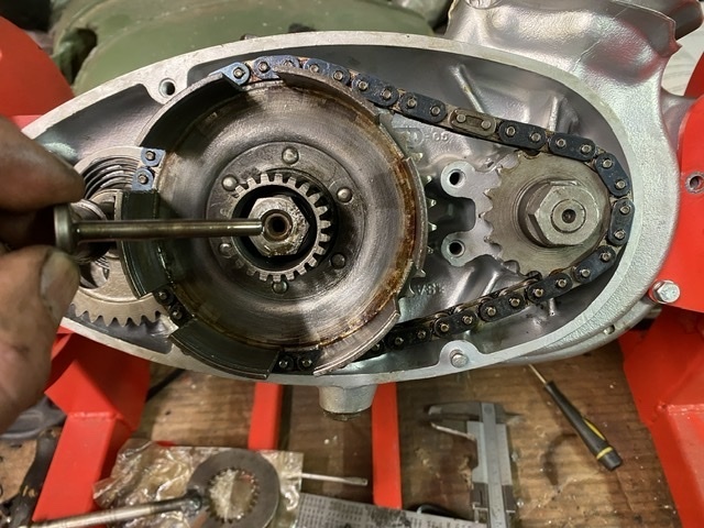
The primary chain can go on next, making sure the split link is properly secured, with the clip the right way around; little fishy swimming with the current… 😀 Once it’s in place the locking tool can be used again to allow tightening of the primary sprocket securing nut on the end of the crankshaft. Then this short clutch actuating “mushroom” shaft gets popped into place:
Then the clutch plates. Starting with a friction plate, then a plain, etc until there’s four friction plates and finally the cover plate.
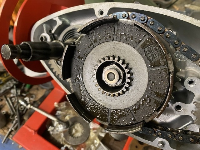
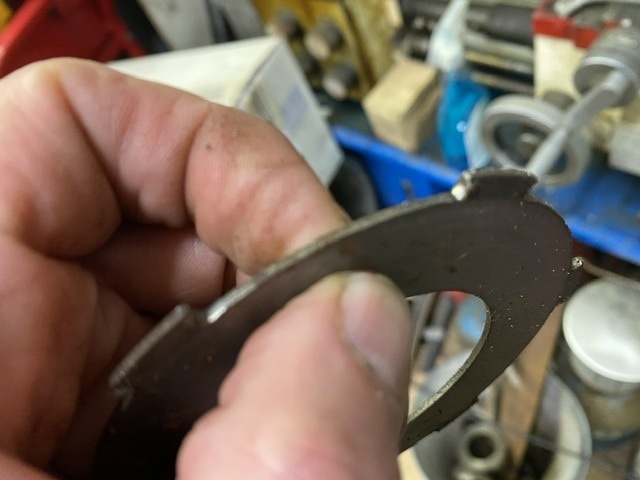
If the driving’s edges of your steel plates are hammered like this one, just replace them.
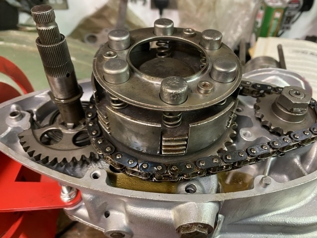
With all the plates in, and the cover plate on, then the springs, their caps and the spring retaining plate are next.
Nexr, you use a compressor to clamp the springs down in order to get the big retaining circlip into place.
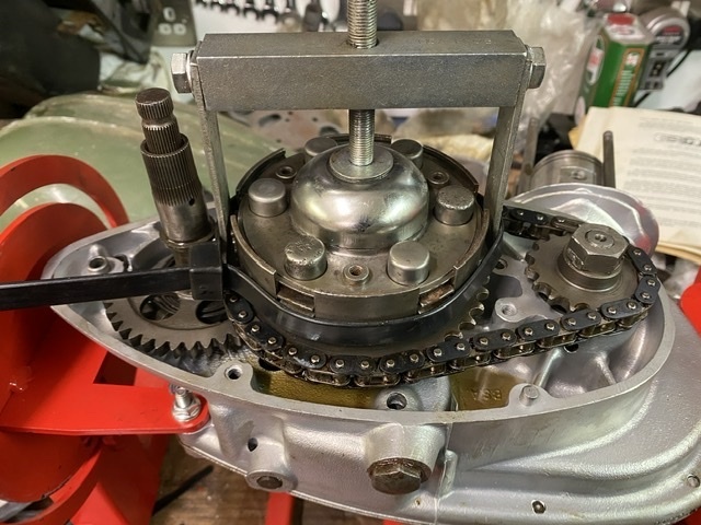
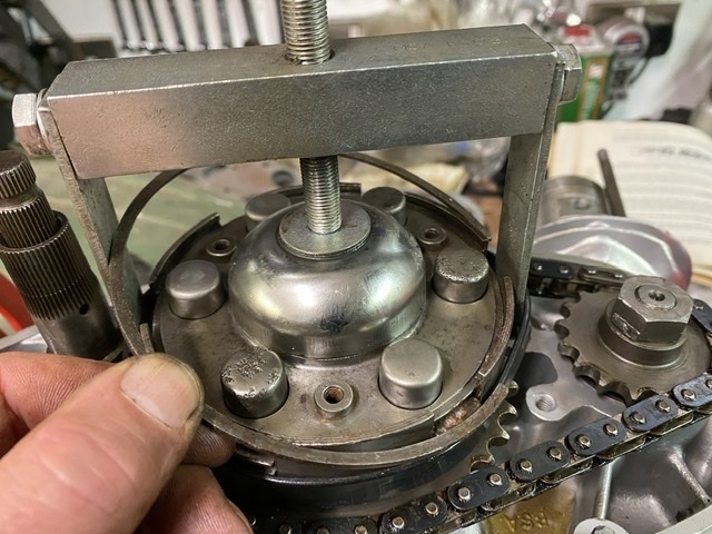
Thake great care to make sure the clip is provided located in its groove in the drum, and the recess in the retaining plate, so that it can’t come out. There’s enough stored energy in the assembly that it would severely spoil your day if it came apart when you were working on it.
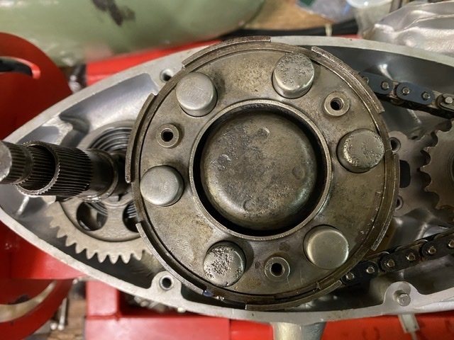
With that done, the top cover goes on. This is to stop the basket spreading under load.
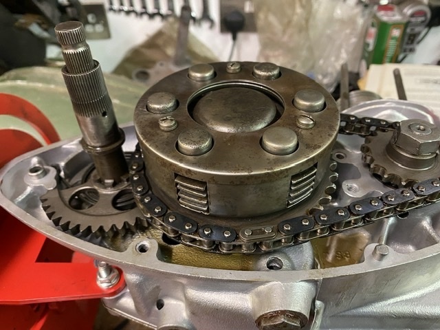
Then there’s nothing left to do this side except fit the outer cover. 😀
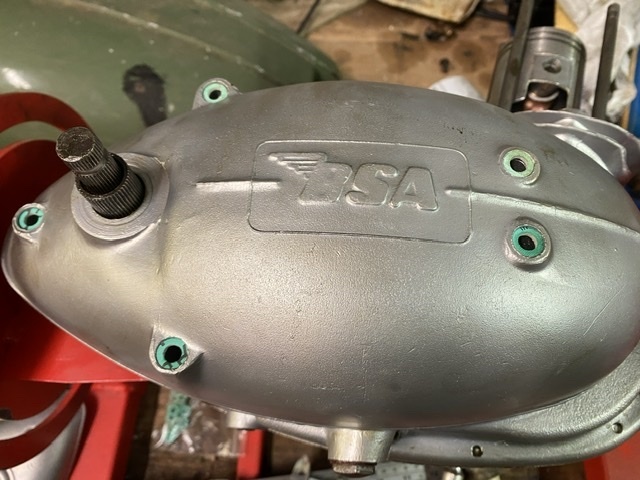
I’m waiting for some bits to come before I can do much more. Nothing major; the “comprehensive kit of engine screws” supposedly for a D1 and D3 turned out to be what was needed for an early D1, so I’ve had to order a handful of extras to suit the later engine (I should probably have got a set for a D5 in hindsight), and rather than my usual reaching for the barbecue/stove/cheap vht aerosol, I have splashed out and got the barrel “cerakoted” in ultra high temperature black, which should last well.
More as it happens. 😀👍
Well, not much Bantaming, if I’m honest, although I have ridden it a bit this year between downpours. More than I’ve ridden my modern bike actually.
It’s still too underpowered though, and no amount of looking at the pile of bits on the bench has seemed to make any of it magically put itself together, so I finally bit the bullet and started on it the other day.
BSA’s manufacturing in the 1950s was pretty much typical of the time. Stuff was made to tight tolerances in some areas, but because manpower was cheaper then, other parts were deliberately made with wide tolerances and either selectively assembled, shimmed to fit, or “fitted” in the true sense of the word by the folks that put them together.
The crank assembly is one area where the wide manufacturing tolerances are overcome by shimming the end float to acceptable levels. You start with the empty cases, and fit just the two large main bearings either side. These are normally a snug sliding fit with the crank stubs. The crank assembly is then fitted, and the two halves bolted up around it. You can then measure the endfloat with a dti. In my case it was about 0.022”.

Once you have that base measure, you have to split the cases again and add shims as necessary to take this down to between 0.004” and 0.006”.

I always aim for as close to 0.004” as I can get, because the addition of a smear of Wellseal around the crankcase mating faces will add half a thou or so to the gap.
With that done, you can add the crank seals each side, and the second smaller drive side main bearing to the cases. This last bearing is always a tighter fit on the crank shaft and it, along with the seals, make measuring the endfloat really hard, so fitting them after sorting all that is definitely the way to go.
Next it’s the gearbox internals. Here they are:

I know gearboxes are a mystery to a lot of people, so I’ll try and explain how this one works, because it’s really a simple thing.
Assembled in the cases the whole lot looks like this. The drive comes in on the left of the picture as you’re looking at it. This is the neutral position, the input shaft is turning in the direction of the arrow all the while the engine is running and the clutch is engaged, as is the large gear highlighted with the yellow marker, but the rest of the geartrain is stationary.

In first gear, the sliding gears are pushed towards the clutch which engages a set of dogs on the layshaft sliding gear into corresponding slots in that big idler, locking it to the layshaft. Drive then passes along the layshaft and into the output gear, which runs concentric to the mainshaft on the right. The sliding gear on the mainshaft is not locked to it in this position.

Second gear is obtained by sliding the gear pair to the right, through neutral, to a point where both sliding gears are locked to their respective shafts. In this position, the drive passes from the mainshaft to the layshaft through the two sliding gears, then back to the output gear.

Finally, top gear is obtained by sliding the gear pair fully to the left, where the layshaft gear is free on its shaft, and the mainshaft one is locked to it’s one, with its dogs engaged in the slots in the back of the output gear. Effectively making the whole mainshaft assembly one piece and the output ratio 1:1 with the input.

Moviing the sliding gear is done with a simple swinging selector mechanism, with a positive stop for each position provided by a spring loaded detent. It’s pushed back and forth by a fairly crude sprung ratchet.
This picture shows the standard layshaft gear and output sleeve gear next to the closer ratio later items I have fitted.

Getting that lot in is relatively simple. The four speed setup is basically the same in its operation, but there’s two sets of sliding gears and a more complicated selector mechanism.
Anyway, the next step is to close up the cases.

With the dowels and and all the case screws torqued up, and the crank and gearbox checked to see they both still turn freely, the gearbox output seal holder can go on next. This is a bit of a lashup on early machines, and is often a source of leaks. Still, as last as the gearbox is kept topped up, the chain never runs dry. 🤣
I found that as soon as I snugged up the mounting screws though, things got too tight and the gearbox mainshaft began to bind. This turned out to be down to the pattern gasket in the kit. The output bearing simply floats in the left hand case. There’s nothing to locate it side to side other than the mainshaft one side and the seal backing plate the other. The supplied gasket was paper thin, about 0.002”, and it meant that the bearing and outposts sleeve gear were getting forced into the mainshaft. I measured the remains of the original gasket and it was much thicker at about 0.008”. So I got some decent gasket paper of the right thickness and made a new one. This sorted the binding issue.

At this point, it’s important to make sure all three gears, and neutral, can be selected easily. If they can’t, then you need to find out why before you go any further. Remember, it’s a constant mesh gearbox, and relies on both the input and output shafts rotating and firm operation of the change lever.
That’s the main cases done, so the next step is the kickstart quadrant. This is spring loaded. You have to put between one and one-and-a-half turns of tension on it. The spring should be wound tight enough that it’s smaller in diameter than the anti rattle shim next to it, but not so tight that it binds on itself when fully rotated. So, tighter than this:

About like this is ideal:

As long as you can still see space between the spring spiral when the quadrant is fully rotated. If this binds then the spring will not last long in service and changing it means stripping the whole clutch out.

Next, the clutch and primary drive. Bantam clutches come in two flavours. Early ones have three friction plates which are fine for the 125 and 150 engines, and generally give no bother with the lower powered versions of the 175, but don’t stand up to much abuse. The baskets for both types are made of solid unobtanium, and have been hard to find in decent condition for years. Secondhand ones do turn up, usually for silly money. I have a small collection of “used but useable” bits that I have rumbled through. I’ve only one early type and, although the basket is useable, it’s the one from the donor engine I stripped last year that had sat full of water, and a couple of the teeth on the primary sprocket were badly pitted.


I think, given the chain drives on multiple teeth simultaneously, I could probably have got away with using it and, given that I’m not going to be riding massive distances on it, it might well have lasted indefinitely. However I do have a much better, later, four plate clutch basket. These are fitted to the last 14 bhp 175s and are a worthwhile upgrade. You can see the deeper basket here with them sat side by side:


The centre drive gear is similarly deeper:

There’s another subtle difference. The early clutches run on a phosphor bronze top hat bush, with a matching pb thrust washer. Most of the later ones use a simple steel sleeve and thinner bush, and a pair of Torrington races to take the thrust loads. Conveniently, they’re interchangeable, but you do need the right drive gear to go with the thrust washer type. D10 clutches use the earlier type of bush with the later clutch, and I had a suitable centre, so that’s what I used. Late Torrington type on the right, plain bush type on the left.

This is what the bush looks like on the wrong centre. It clearly shows the mismatch. If you looked from the side you’d see the bush is too thin as well, with the centre poking out by a mm or so.

And this is how it should look:

I could have used the later type along with the Torrington races, but I’ve only got one set and I want to use them on the other engine.
With the clutch in place, I used this tool I made years ago from an old clutch friction plate to lock the gearbox shaft and torque the centre nut up.


The primary chain can go on next, making sure the split link is properly secured, with the clip the right way around; little fishy swimming with the current… 😀 Once it’s in place the locking tool can be used again to allow tightening of the primary sprocket securing nut on the end of the crankshaft. Then this short clutch actuating “mushroom” shaft gets popped into place:

Then the clutch plates. Starting with a friction plate, then a plain, etc until there’s four friction plates and finally the cover plate.

If the driving’s edges of your steel plates are hammered like this one, just replace them.

With all the plates in, and the cover plate on, then the springs, their caps and the spring retaining plate are next.

Nexr, you use a compressor to clamp the springs down in order to get the big retaining circlip into place.


Thake great care to make sure the clip is provided located in its groove in the drum, and the recess in the retaining plate, so that it can’t come out. There’s enough stored energy in the assembly that it would severely spoil your day if it came apart when you were working on it.

With that done, the top cover goes on. This is to stop the basket spreading under load.

Then there’s nothing left to do this side except fit the outer cover. 😀

I’m waiting for some bits to come before I can do much more. Nothing major; the “comprehensive kit of engine screws” supposedly for a D1 and D3 turned out to be what was needed for an early D1, so I’ve had to order a handful of extras to suit the later engine (I should probably have got a set for a D5 in hindsight), and rather than my usual reaching for the barbecue/stove/cheap vht aerosol, I have splashed out and got the barrel “cerakoted” in ultra high temperature black, which should last well.
More as it happens. 😀👍


