|
|
|
|
|
Next time warm the oil - stand the bottle int he sun, a pan of just boiled water or even microwave it as a Lancia specialist once told me - you have to fill an integrale gearbox down the long dip stick tube and warming it makes it flow so much better. I'm not too sure about what microwaves will do to the oil molecules and an oil guy never came back to me when I asked. And I do like your car - it looks rather good. Wish I'd thought of this at the time - it was a right bloody pain of a job  Cheers for the compliment - I reckon the car looks great in white. The windows also have a light tinting film on them which I think sharpens it up a bit. It could definitely do with a respray but looks good from six feet away. At least this way I won't worry too much about it getting scratched in a carpark... |
| |
|
|
|
|
|
|
|
|
|
|
Yeah what he ^ said. The seats have a different pattern too.
Ive had a few triumphs through our workshop for rust repairs recently. Another one or two yet to turn up. I love these cars. My first ever car was a French blue 2500tc and Ive had another 4 since. So very underated in value and there are heaps of them kicking about still used as dailies in NZ.
|
| |
|
|
|
|
|
Jan 12, 2020 23:55:22 GMT
|
Well, another couple of weeks have passed and against all odds another few jobs have been ticked off of the to do list – the main focus this time round being the rather grotty cooling system which seemingly last saw anything that could be described as a ‘better day’ back in the late 1990s. The hoses were perished and swollen, the coolant a very dubious shade of brown and the fan belt, well actually the fan belt wasn’t too bad, but you get the gist of things. Some replacement hoses were definitely the order of the day – luckily the blue car generously donated the new top and bottom hoses which the previous owner had put on just before it came into my ownership. The remaining assortment of smaller hoses I had bought from Rimmer Brothers in the UK, along with a new thermostat and gasket. Before fitting the hoses however, the system needed a thorough flush to remove the existing coolant and any associated sludge that had built up over the last 30-odd years. The system was drained by removing the bottom hose and both the radiator and block flushed and back-flushed several times until only clean water emerged. After removing the heater hoses and moving the heater controls to hot, the heater core had the same treatment (this yielded a particularly appetising pan of brown silty goo), as did the small diameter pipe that runs behind the carbs. I would have done the same with the steel water return pipe which runs behind the exhaust manifold but somewhat annoyingly this disintegrated in my hand when I removed the heater hose from its T junction. 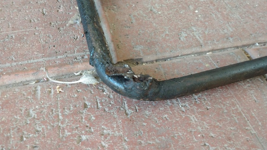 Being a mild steel pipe, corrosion here is a common problem which many owners choose to rectify with a stainless steel replacement from Triumph supplier Chris Witor. However before ordering one I decided to inspect the engine I had removed from the parts car just to see if its water pipe was at least serviceable enough to use as a stop-gap measure in the short term. To my surprise, not only was the spare pipe in great condition but it was also copper rather than mild steel and therefore completely free from corrosion. I’m not sure if this is a bespoke item made by a previous owner or their garage (or their plumber) or whether these were readily available at some point. Either way it saved me a lot of time and worry (and money – the stainless item weighing in at around $80/£40 including postage). 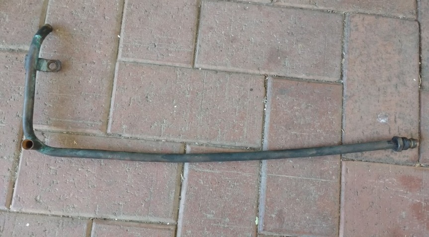 Whilst I’d had some luck finding a replacement pipe, replacing it wasn’t quite as straight forward as I had hoped. The pipe is easily freed from the block – is is held on by a single bracket at the rearmost exhaust manifold stud, two heater hoses and a compression fitting at the water pump end (I’ve heard these compression fittings can be a pain to undo but mine didn’t put up a fight). Getting it out is less easy – certainly on the S model – as the power steering pump and bracket preclude it from being pulled straight off of the car. After much wriggling around, trying to find that one sweet angle at which it would clear both the exhaust manifold, the power steering pump and the radiator, I gave up and decided the easiest option was to remove the manifolds to give myself a bit more room. Although not a task I had planned to do, it’s not the trickiest job in the world (providing you don’t encounter any non-compliant studs) and it gives great access to the coolant hoses at the rear of the block, thus making replacement a lot easier. Removal of the inlet manifold (complete with carbs) just requires the disconnection of the throttle and choke cables, a few fuel, vacuum and PCV hoses and nine nuts (six of which also hold the bottom of the exhaust manifold in place). Removal of a further 4 nuts frees the top of the exhaust manifold, which can then be pulled gently away from the head.  With the exhaust still attached, the manifold is only free to move about an inch or so – but luckily this was all that was required to free the water pipe from its small and rather toasty prison. The old one was removed (and promptly chucked in the bin) and the new copper replacement fed in to take its place. I used a little bit of PTFE tape around the compression fitting to ensure it was watertight but other than that the fitting was a thoroughly unremarkable event. Whilst the manifolds were off I replaced the various heater and other hoses at the rear of the block burning through my stockpile of new (well, newish) jubilee clips. I used the proper, correctly shaped hoses rather than just lengths of generic half inch heater hose as a) they look neater, b) it reduces the risk of kinking and suppressed coolant flow and c) they’re really not that expensive in the grand scheme of things. 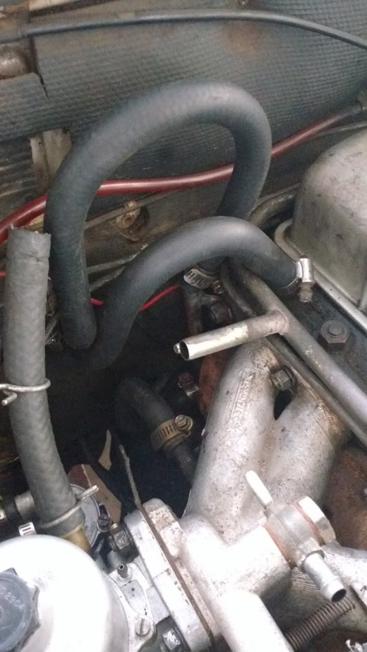 With the hoses replaced, the manifolds were reattached to the head using the original gasket which looked to be in good condition. I was careful when tightening the manifold nuts not to go overboard with my crazy Popeye-esque strength just to avoid any sheared studs and heartache. I came away unscathed in this respect. Next I turned my attention to the larger hoses – both of which needed some Stanley knife-based ‘adjustment’ (this does not usually bode well for the integrity of my fingertips). The car has two electric cooling fans fitted at the front of the radiator which I presume used to be controlled by a long-defunct thermo switch which was mounted on the front slam panel. When this failed the previous owner ran a bypass circuit into the car where a small toggle switch could be used to control the fans manually. This was seemingly never actually fixed to anything and was just floating around beneath the dashboard. This, coupled with the fact that all electrical connections had been made using insulating tape, spurred me on to rectify the situation. A while ago I had purchased a Davis Craig thermal fan switch together with a adaptor kit to enable the probe to be fitted properly into the top hose, instead of hanging out one end of it which looks untidy and, from experience, invariably leaks. Fitting was fairly simple, 17mm of hose is cut out and the adaptor is fitted in its place. The temperature probe fits into the adaptor and runs out to the thermo switch – which I mounted on the slam panel using the same holes which held the bracket for the old switch. 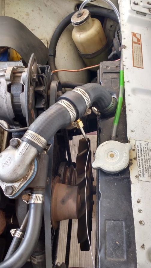 Two short lengths of wire were then cut and used to join the thermo switch back to the original fan wiring loom, the result being functional, although not exactly factory (I’ve never really been a fan of these aftermarket thermo switches with their very obvious and messy probe cable) . 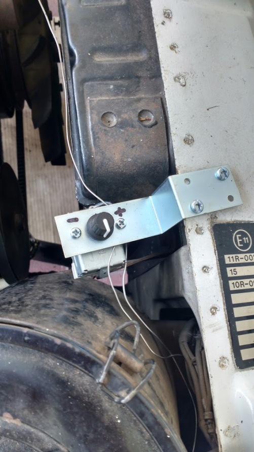 For extra control and as a backup I also ran a bypass circuit into the car – although unlike the previous owner I went the whole hog and terminated in a proper automotive toggle switch which was mounted to the lower edge of the dashboard. Hopefully I’ll never need to use it but it’s reassuring to know it’s there just in case. 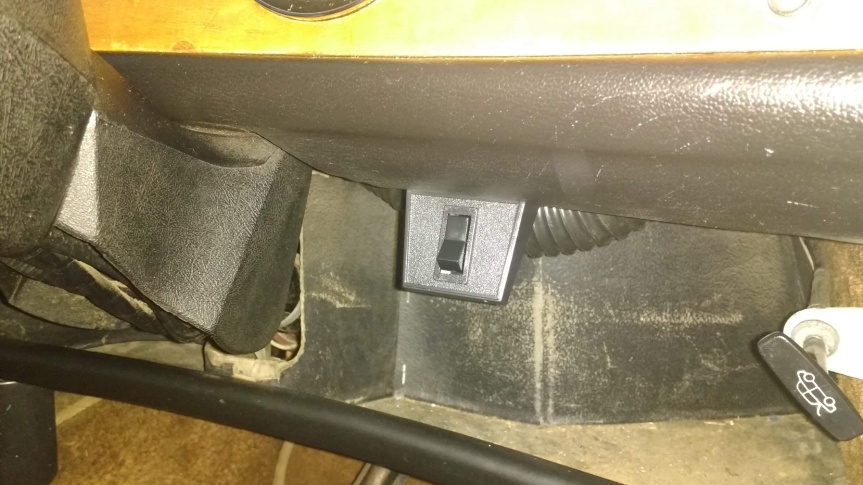 The bottom hose also required some surgery as it originated from the parts car which lacked power steering. The S models did not use the same single-piece bottom hose but instead used two shorter hoses connected by a metal pipe which is of small enough diameter to pass between the power steering pump and its pulley without being chafed. Cutting the middle section out of the bottom hose and just using its two ends did the trick. 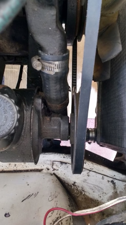 The connecting pipe for the two bottom hoses is also mild steel and mine was quite badly corroded at one end – although in this case enough metal remains for it to be used quite safely in the short term. A stainless steel replacement has been ordered from Chris Witor but in the meantime I used some JB Weld epoxy to fill some of the depressions left by corrosion just to help the bottom hose seal as well as possible and to prevent leakage. When the replacement pipe for the lower hose arrives I plan to run a coolant flushing product through the system before I drain and re-flush the radiator, heater core and block. That should hopefully shift any remaining gunk and ensure the car keeps its cool at least for the next few years. So that’s the cooling system dealt with for now – there are just a couple of minor jobs to complete at this stage and she’ll be good to go. I’m looking forward to getting out and about and exploring some of SA’s beautiful countryside in the old girl. |
| |
Last Edit: Jan 12, 2020 23:55:50 GMT by llessur
|
|
|
|
|
|
|
Blimey. All I did was blink and a month passed by. Well to be accurate I got distracted renovating a bathroom and, because of my well-documented inability to focus on more than one task at any given time, work on the Triumph pretty much slowed to a stop. However, the stars are gradually aligning – the bathroom is finished and the Missus is overjoyed that we once again have a functioning toilet so I’m sensing an opportunity to sneak out of the house whilst she’s not looking and have another poke around in the oily depths. Once I had finished faffing around with the cooling system I made a last-minute executive decision to try to sort out the clutch which bites about 5mm from the bottom of the pedal travel and makes the car a bit difficult to drive. In the hope it was a hydraulic problem, I swapped over the known good master cylinder salvaged from the TC, fitted a brand new 7/8″ bore slave cylinder procured from Chris Witor and bled the system thoroughly but this had no effect on pedal travel. I presume that the problem is inside the bell housing – most likely the tapered pin securing the clutch release fork to the cross shaft has sheared and needs to be replaced. It’s a gearbox out job then. Luckily/annoyingly I’ve been there before… Whilst I haven’t had a chance to do much actual work on the car, it has needed to be shuffled around my vast estate a few times to make way for plumbers digging up my driveway and this has drawn my attention to the less-than-healthy condition of the engine. It knocks a bit when starting from cold (they all do that sir) and it enjoys spraying my driveway with a fine mist of oil from the exhaust pipe each time it runs. I’ve had my suspicions about the existing lump since I bought the car – the oil was black and filthy, the filter canister contained no paper element and the valve gear was caked in an appetising layer of black sludge (I did buy it from a breakers don’t forget). Out of morbid curiosity I’ll run a compression test and, if I’m feeling really fancy, might hook up my oil pressure gauge just to see what’s going on but seeing as it’s not the original block supplied with the car from new (the engine number is from a 2.5PI) I have no particular concerns about swapping it over for something a bit less curse word. 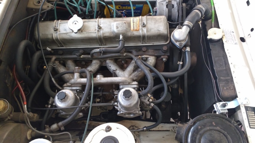 As luck would have it, my garage floor is still adorned with the 2500 lump I removed from the parts car prior to it ‘moving on’. Whilst I don’t know much about the history of this engine it has a nicer aura than the one that’s currently in the car. When it came into my ownership the oil was clean, the filter element was new and the valve gear was sludge-free. The block and head also seem to be sporting various new gaskets, new freeze plugs and a fresh(ish) coat of paint which makes me wonder if it has been rebuilt at some point in the past. Annoyingly I didn’t run a compression or oil pressure test on it whilst it was up and running in the TC but it didn’t knock from startup or spray oil from the exhaust and has fairly minimal fore-aft play in the crankshaft so my money’s on it being a safer bet in the long run. 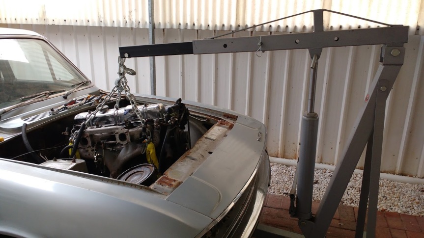 So, seeing as the gearbox is going to have to come out to fix the clutch I thought I might as well go the whole-hog and swap the engines over at the same time. I also have a newly-rebuilt overdrive gearbox sitting all seductively in the corner of my garage which might as well be put to good use and swapped in too. So, that’s the to-do list sorted for the coming weeks then, but what about more immediate progress? Well, to give myself an ‘ooh, something is happening’ ego boost I decided to start small and swap out the front wheel bearings. Having been off the road for 10 years or so, the bearings needed to at least be stripped, cleaned and re-greased so I thought I might as well go the extra mile and fit new ones. A set of replacement Timken bearings were sourced from purveyor of fine Triumph parts Chris Witor a few months ago and have been sitting on the shelf in my garage ever since. 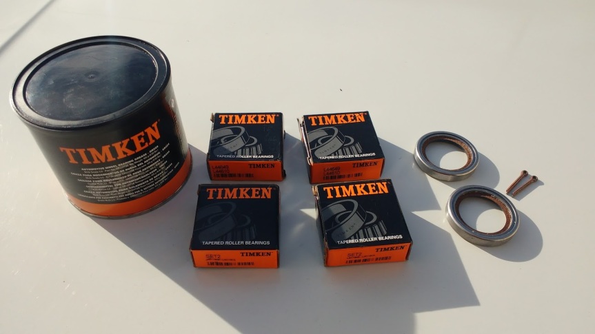 The replacement process begins, as with all good stories, with the jacking up of the front of the car and securing it on axle stands. The brake caliper needs to come off first – it’s technically held on with two bolts but removal and refitting is much easier if the bolts holding the strut to the vertical link are loosened slightly too. Once they’ve been slackened, the caliper can be unbolted and suspended from the front coil spring by a length of wire to avoid any tension being put on the brake flexi hose. 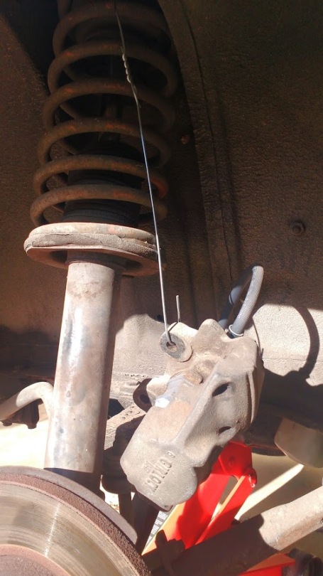 To remove the hub itself the dust cap needs to be levered gently off of the centre of the hub, exposing the castellated hub nut. The split pin securing the nut to the stub axle can be pulled out with pliers, after which the nut can be removed leaving the hub free to be pulled straight off. This process may or may not leave the inner bearing roller and/or grease seal attached to the stub axle – if so they can be pulled or gently tapped free. If the bearing rollers have remained in the hub, they can be pulled out leaving just the races, which are a press-fit in their seats. Each race can be tapped out from the opposite side of the hub through the two small notches that BL kindly machined – I have a handy box of long carriage bolts stashed away for such purposes. 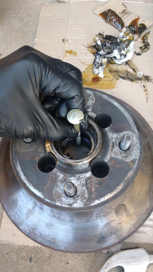 You’ll probably find it cleaner and easier to see what you’re doing if you remove as much rancid old grease as possible from the hub assembly first – especially if a previous owner or their friendly mechanic has stuffed the cavity full of the stuff as is often the case (and by all accounts completely unnecessary). A few bold taps of the hammer, alternating between each side of the race should see it pop right out. Be bolder if not. Repeat for the other race et voilà – the disassembly process is complete. Enjoy a pat on the back and have a beer. 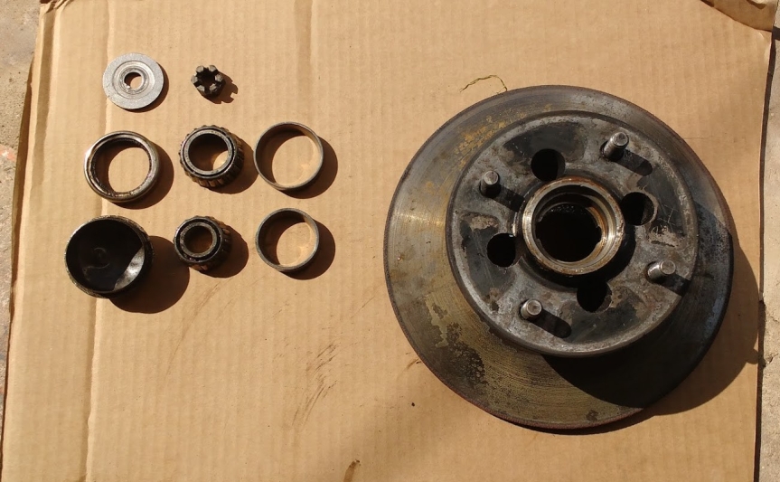 Despite having new bearings to fit, out of curiosity I cleaned off the old bearings and their races to see what condition they were in. Whilst not showing heavy wear or damage, the races showed some signs of light scoring and heat-related discolouration so their replacement was definitely due. The grease also smelled a bit burnt and around the bearings it had a very low viscosity, resembling more of a heavy oil than a grease. Whether this was age or heat-related deterioration, or the wrong type of grease had been used at some point in the car’s maintenance history I don’t know, but it felt good to be cleaning it all out. 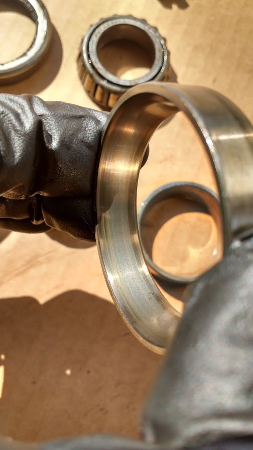 The first step of reassembly is to drive each of the races into its seat in the hub. There are several ways of doing this – you could use a hydraulic press (easiest, but I don’t have one), you could drive it in with a suitably sized socket, or you can drive it in with a punch of some description. Whichever method you choose, the aim is to ensure the race is fully seated in the hub without inflicting even the slightest damage to the surface on which the rollers will run. Being the daredevil maverick I am, I chose Option 3 and used the same non-hardened carriage bolt that I used to remove the races to drive them home – tapping the races progressively into the hub, working around the top lip in a 12, 6, 3, 9 o’clock pattern. This has to be done extremely carefully as it would be very easy to slip and scratch the bearing surface rendering it scrap. Taking it slow and steady I got away with it – the obvious change in note of the hammer tapping the race being the signal that they had bottomed out in their seats without a single slip, scratch or bludgeoned finger. Another celebratory beer? Thank you, but not whilst I’m working with tools… 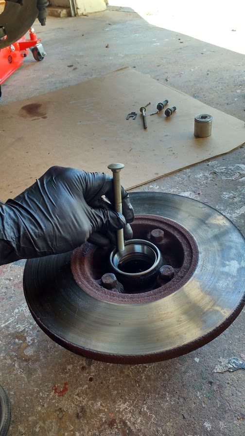 The next step in the assembly process is to pack the new bearing rollers with a dedicated wheel bearing grease – I used a Timken grease as presumably they are best placed to know the lubrication requirements of their own products. Again, there are a couple of options here – you can buy a fancy bearing packer contraption or you can do it the fun, messy way. I chose the latter of course – this involves placing a nice big blob of grease in the middle of one palm and with the other hand biting away at the blob with the outer edge of the bearing roller until fresh grease is pushed through and out of the other side (see picture below). This is repeated progressively around the circumference of the bearing until it is fully greased. I then also run the grease around the rollers with my fingers to ensure they are covered. The races installed in the hub also get a coating to avoid dry spots. 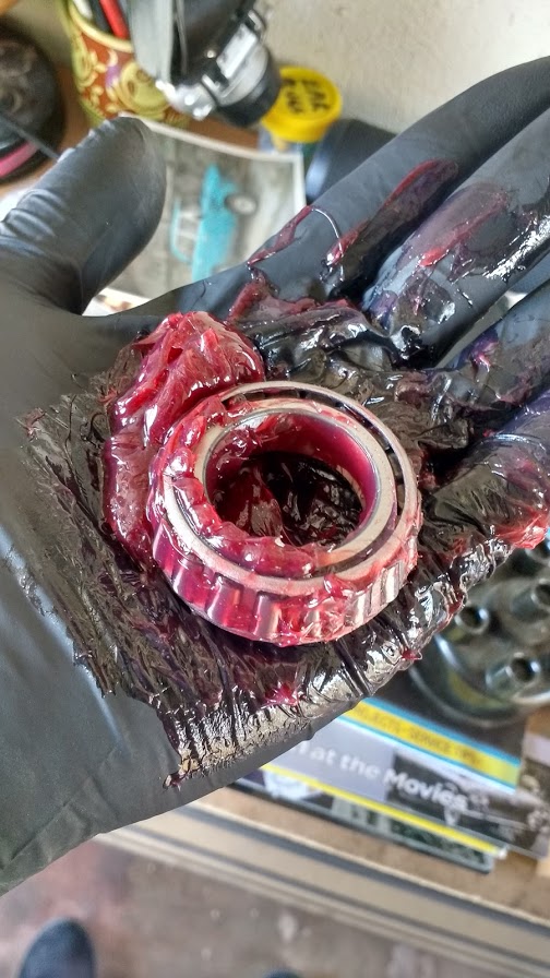 Next the grease seal needs to be fitted to the stub axle – I went for the decent ones with leather inserts available from Chris Witor. These can be a bit tight and therefore tricky to fit, but a very light smear of grease and some gentle persuasion with a small hammer around their perimeter saw them sitting where they should be. At this stage the inner bearing roller can be slid over the stub axle – it might need a careful tap if there is a small lip for it to slide over (although if there is significant wear to the stub axle it might be time to consider a replacement) but I am reliably advised that it shouldn’t be an interference fit. Once the inner roller is in place, the hub assembly and outer bearing can be installed, followed by the large washer and castellated nut (although don’t fit the split pin just yet). Give both sides of the brake disc a good going over with some brake cleaner to remove any wayward grease and re-attach the brake caliper (don’t forget to tighten the strut to vertical link bolts to the correct torque). 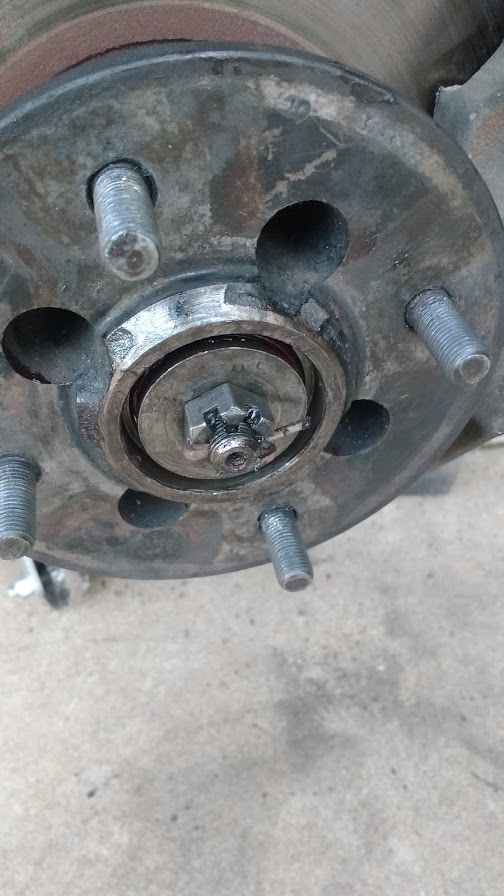 The final step in the process is to adjust the bearing – tapered roller bearings should not have a pre-load (i.e. an axial force which is great enough to remove play in the bearing components), nor should they be too loose. The tightness of the hub nut determines the pre-load on the bearing – the aim is to find the sweet spot in which the nut can be locked by the split pin that will allow a very small amount of detectable play. The threaded portion of the stub axle has two holes drilled through it at right angles, meaning there are 12 positions in which the split pin can lock the nut in any 360 degree revolution. My technique, and there are many, is to temporarily fit the road wheel and then tighten the hub nut with a socket to ensure that all bearing parts and the rear grease seal are seated correctly. Next I back the nut off again until there is free play in the bearing and then very gradually re-tighten until the point at which all the play is removed. Finally I back the nut off until the next available hole for the split pin is available – in this position if the wheel is rocked from top to bottom I should just be able to feel some movement in the bearing (if there is still no movement detectable then I back off again to the next hole). Remember with taper roller bearings that a little bit too loose is generally better than a little bit too tight but, as a rule, if you can hear the movement then it’s probably too loose. It can sometimes take a few attempts to get this right and the bearings should also be re-adjusted after a few miles to ensure that any additional play gained through the seating of the bearing components is accounted for (so make sure you order a couple more sets of split pins as they should not be re-used). So that’s my update – both front wheel bearings are replaced. The next jobs on my list are not so small. Watch this space… |
| |
Last Edit: Feb 11, 2020 2:29:46 GMT by llessur
|
|
trimtechniques
Part of things
  Porsche 928 4.7 ltrs of German grunt. Mazda MX-5 MK1 Dakar. VW T4 camper
Posts: 158
|
|
Feb 11, 2020 23:19:45 GMT
|
|
Love these old Triumphs! Bookmarking this, lovely car.
|
| |
|
|
|
|
|
|
|
No one likes doing the same job twice. I, especially, don’t like doing the same job twice. And yet here I am doing the same job for a second time running. A large part of me just wanted to say sod it and send the car to a mechanic to do the gearbox and engine swap, but the increasingly miserly aspect of my personality couldn’t look past the cost of doing so, as well as the fact that I’d be missing out on the opportunity to be able to say that I’d done it myself. Plus, nothing helps you learn more about your car than pulling its innards out. There are two schools of thought when it comes to removing the engine and gearbox from a Triumph saloon – the first being to raise the car on axle stands, remove the engine and suspension cross-members and then drop the two as a single unit before sliding out from under the car. Whilst almost universally accepted as the easiest option I’m reluctant to go down this path because: 1) by my calculations the front of the car will need to be raised at least 700mm for the engine to clear the front valance and I don’t think my existing axle stands will have the required height for this and 2) I need the car to remain mobile whilst I undertake any engine rebuild work required and don’t really want the hassle of refitting the suspension in the interim. The second school of thought is to remove the engine and gearbox as separate units – the gearbox from below and the engine from above. I’ve done this before on the parts car and it worked well. That said, when it comes to refitting, I may still investigate the option of installing the two as a unit from beneath, given that I won’t have gravity on my side when it comes to refitting the gearbox. The first job was to lift the car high enough for the gearbox to come out from below. Behold my timber-based Triumph raising method (patent pending and fully health & safety compliant)... 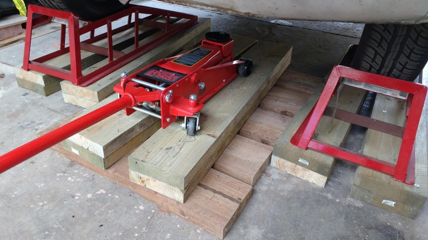 So, with the car at the right height, I headed down the now well-trodden path of pulling the gearbox – starting with the removal of the exhaust system. This has to be removed in two pieces as it passes through the chassis at the rear of the car – therefore the rear section has to come off first, followed by the middle and front sections (I removed these as a single unit to avoid having to split them). The rear section is attached by two rubber mounts along its length which, once removed, allowed the unit to be tapped out of its joint with the middle section with the assistance of a large wooden adjusting mallet. The front and middle sections are fixed at the manifold as well as a bracket near the gearbox cross-member. Once these were undone the pipe could be dropped and removed from the car. 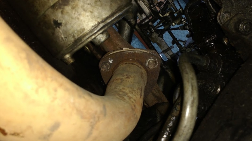 With the pesky exhaust pipe out of the way, the real fun of gearbox removal could begin – the first step of which was to unbolt the four bolts holding the propshaft to the output shaft flange. I found the easiest way of doing this was to undo the two bolts which I had access to and then lift the back of the car enough to turn a rear wheel to bring the other two round to an accessible position. Once all bolts had been removed, the front end of the prop could then be lowered to the ground and slid aside for access. 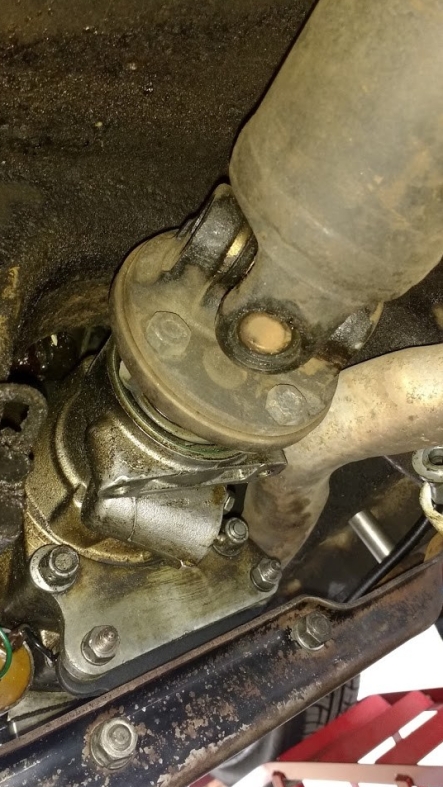 With the prop and exhaust dealt with, the next step was to remove the gearstick, which is done from inside the car. This is held in place via a metal cup attached to the gearbox selector housing. To remove, the trim panel around the gearstick needs to be gently unclipped (a proper trim removal tool comes in handy here) and the single bolt holding the cup in place removed. Then, with the wiring for the overdrive switch unplugged, the cup is pressed and turned to release allowing the gearstick to be withdrawn from the car. 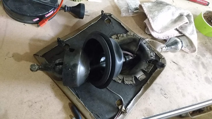 The final preparatory steps before dropping the ‘box were to remove the speedo cable from the gearbox and unplug the wiring from the overdrive solenoid and inhibitor switch, as well as the reversing light switch – making sure to note the correct locations of the wires to prevent headaches when I eventually put everything back together again (potentially decades later given my track record). The gearbox is held in place by a mount at the rear, as well as somewhere in the region of 500 bolts between the bellhousing and the engine backplate (actually it’s around the 15 mark, including three studs, but it feels like an awful lot more when you’re lying on your back trying to remove them in the dark). The fixings at the top of the bellhousing are only really accessible with the gearbox dropped so I dealt with those first. Dropping the gearbox involves removing the supporting cross-member from the car. As it is preferable for the lowering process to happen in a controlled manner (as opposed to very quickly and via my face) the cross-member first needs to be supported with a jack. As my head was underneath it I went all-out and chucked in an axle stand as well. With this in place, the four bolts holding the cross-member to the car were removed, being careful to retrieve and set aside the myriad of washers, bushes and spacers that followed. The jack was then lowered slowly to drop the gearbox down as far as it would travel (i.e. until the cylinder head rests against the bulkhead), at which point the cross-member and mount could be unbolted from the ‘box. 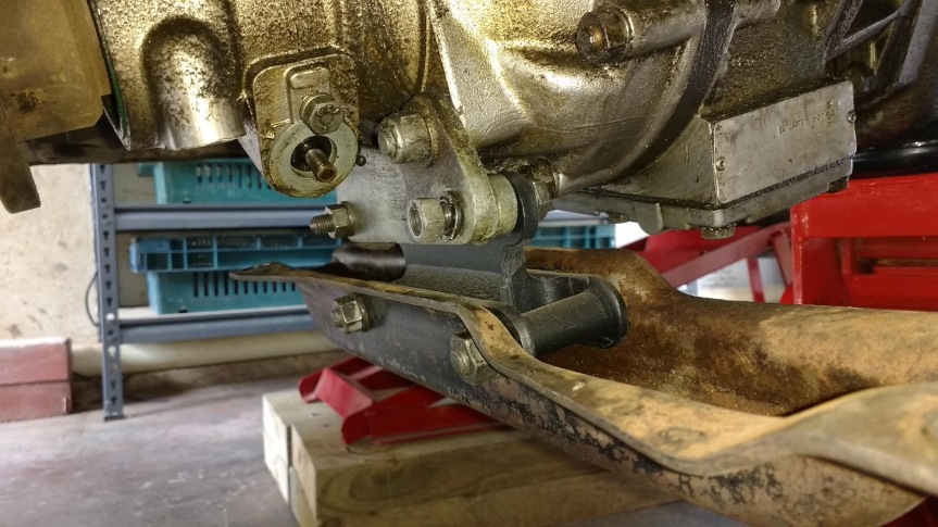 With the gearbox lowered, all of the bellhousing fixings became accessible, or at least as accessible as they’d ever be – these could be removed with something varying from complete ease (in the case of the lower ones) to real hassle involving multiple socket extensions, psychic ability and unhumanly bendy arms (in the case of the top ones). Two of the bolts hold the clutch slave cylinder mounting plate in place – this was moved aside and supported with a bit of wire to prevent undue stress on its hydraulic line. Having removed a 2500’s gearbox before using only a trolley jack, I had procured a secret weapon this time round to allow for easy removal – a transmission jack adapter. This nifty piece of equipment turns a standard trolley jack into a transmission jack, great news for skinny armed folk like myself. As well as forming a secure cradle to support the ‘box, the adapter also features a tilt mechanism, which looked like it would make removing the gearbox and then aligning it upon refitting a bit of a doddle. 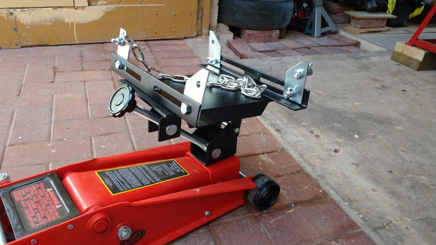 However, my optimism was annoyingly short-lived as it soon became apparent that the overall height of this unit was too great to allow the gearbox to be dropped from the car completely. In fact, even at its lowest height the top half of the gearbox remained well within the confines of the gearbox tunnel, leaving no options for rolling it out to the side or similar. 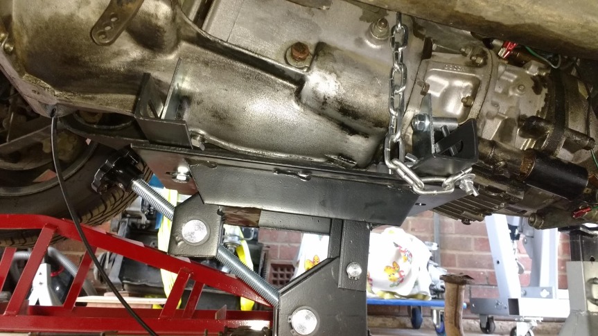 Not to be deterred, and with a celebratory cup of tea at the front of my mind, I shifted my strategy towards a two-stage approach, using the jack to lower the ‘box onto an interim support of a timber beam securely lashed to the wheel ramps and a second jack positioned at the rear mount point. Two of the supporting lugs on the transmission jack adapter could then be removed, allowing it to be slid out to the side and out from under the car. 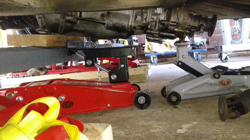 The final step in removal involved using the jack to lower the rear of the ‘box onto a bespoke cushioned surface (some bags of garden mulch and potting mix). One side of the timber beam could then be unlashed and slid down the wheel ramp to bring the front end of the box down to ground (or mulch) level. Not exactly textbook but it worked – the only damage being a small tear in one of the bags of mulch, which I’ll just have to learn to live with. 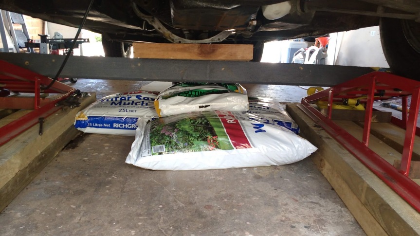 So the old gearbox is out. I haven’t yet had the time to inspect the release fork pin to see if it confirms my suspicions that it’s broken – but on initial inspection the release bearing is certainly past its best, having worn a considerable groove in the pressure plate fingers. 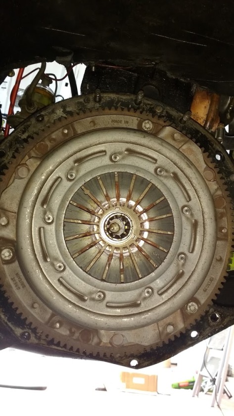 I have all new clutch components to fit to the new gearbox so I’m not too concerned about any of the existing clutch mechanism at this stage, but it will still be interesting to find out what’s been going on in there. The next step is engine removal. I’ve made a small start on this in the form of ancillary component removal and labelling of wiring but the bulk of the work will have to wait until next time. 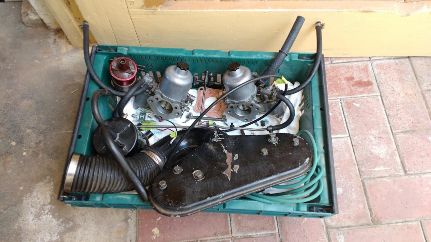 In my case I also have to worry about the power steering pump and air con compressor (defunct) which were not part of the equation when pulling the engine from the parts car. However with the radiator, flywheel and viscous fan removed I think there should still be room to remove the engine from above. Otherwise it will be time for Plan B – which doesn’t exist yet. |
| |
Last Edit: Feb 25, 2020 3:56:48 GMT by llessur
|
|
|
|
|
|
|
We should have a chat sometime. I am in Whyalla with a white TC2500 with a brown interior that needs a lot of work. I have just started to put it back on the road. It is currently getting the exhaust sorted as the last owner ran it up along the tail shaft and rubs on it. I have it booked in in August for a full respray and body repair. it was someone's project car for 30 years and when he passed on, his kids wanted nothing to do with it and I thought it was too good to crush into a cube. 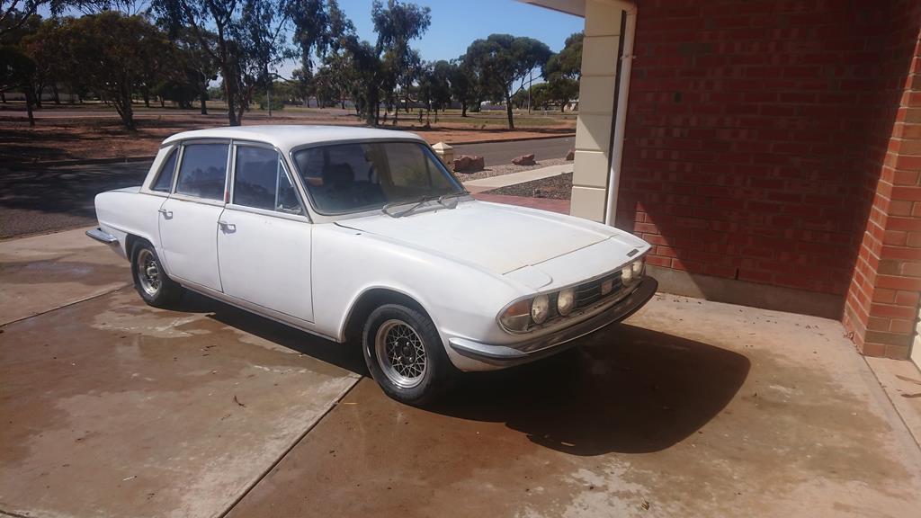 |
| |
|
|
|
|
|
|
|
Finally, after a few weeks of life getting in the way of classic car fiddling I’ve found some time to get down and dirty with the beast – picking up where I left off last time with the engine removal. I’d already removed some of the ancillary bits and pieces – air box, carbs, manifolds, coil etc and removed and labelled all of the wiring to the block. Next in line for attention were the power steering pump and air con compressor – the former would stay with the car whilst the latter was too big to be removed with the engine in-situ and would be lifted out with the block. The power steering pump is secured to both a bracket on the side of the block and to the front engine plate. After freeing the pump from these fixings I tethered it to the suspension turret to prevent undue strain on the hydraulic pipes and hoses. 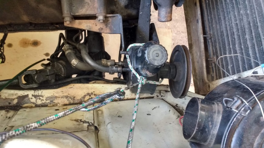 Nestled in under a slightly modified (i.e. butchered) battery shelf, the AC compressor is too big to extract from the car with the engine in-situ and was therefore disconnected from the rest of the system by undoing two hoses (I guessed correctly that the refrigerant had escaped long ago) and a couple of electrical connections so it could be lifted out attached to the block. I was initially in two minds about whether to keep the AC system or not, given that it takes up room in the engine bay, doesn’t work and will most likely be expensive to fix. However it would be a great asset if working and the retro interior unit looks good so I have decided to reinstate it as is (i.e. not working) in the short term with a view to recommission it at some point in the future. I have temporarily sealed off all of the hoses and connection points as best as possible to keep the system clean and hopefully moisture-free whilst it is disconnected (not that moisture’s a massive issue in the South Australian summer). 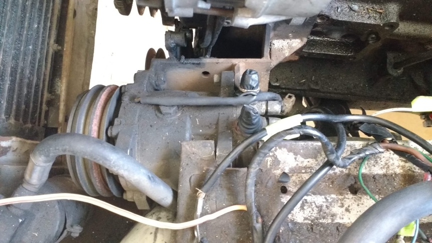 Learning from my previous experience of extracting a 2500 engine from above, I removed the clutch assembly, flywheel and bell-housing mounting studs from the rear of the block, as well as the cooling fan from the crank pulley. The radiator was also removed and stored safely (incidentally a sticker on this showed it had been re-cored fairly recently – probably only a year or two before the car was decommissioned – and looks to be in great shape). This reduces the length of the block as much as possible and means that the chances of fouling on the bulkhead or slam panel during removal are greatly reduced. Thanks to this preparation work, lifting the block out was relatively pain-free – it was connected to my engine crane via two one-tonne lifting slings and after the engine mounts had been unbolted it was liberated from the car with only gentle manoeuvring around the bulkhead and steering rack required. 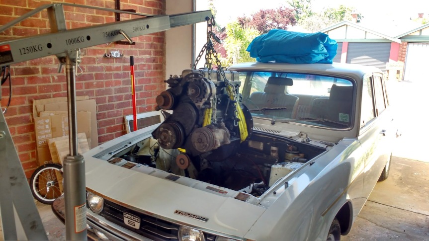 With the engine out I’m going to take the opportunity to address a few little issues in and around the engine bay. One urgent issue that will definitely be rectified before the car returns to the road is the replacement of the rubber steering column coupling which is well on its way to becoming a useless collection of smaller chunks of rubber and metal. As luck would have it a supplier erroneously included one of these in a parts order I made a year or two ago and it’s been sitting on the shelf in my garage ever since so that will be a quick and free solution to a potentially dangerous problem. There’s apparently a bit of an art to fitting these involving a large jubilee clip so I’ll brush up on that before I get stuck in. 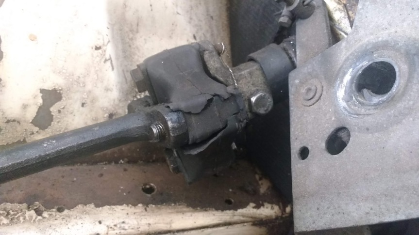 The engine mounts don’t look too bad so in the interests of keeping costs down I’ll probably stick with these rather than take a gamble on some new ones which may or may not last more than a few hundred kms. 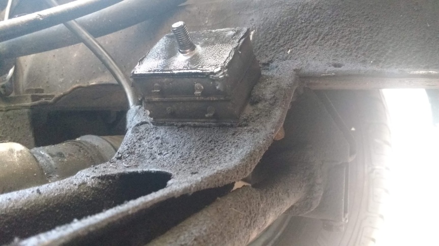 The offside chassis leg, whilst very solid, has suffered from paint blistering where brake fluid has spilled down onto it over the years. It’s currently protected by a nice film of oil and grease but I’ll try to tidy this up before the engine is reinstalled. I’m not aiming for concours, especially under the bonnet, so I’ll try to match the paint up as best as possible and do a quick tart up with a rattle can for now. 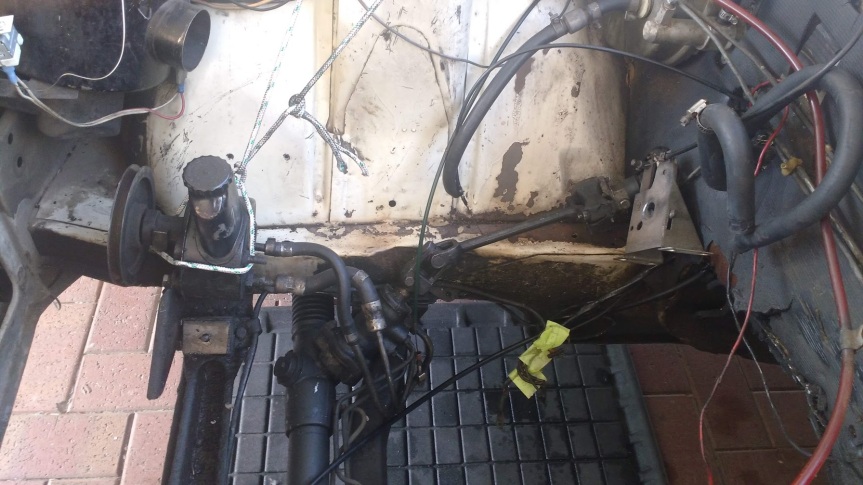 Having decided that I’d procrastinated long enough by digging around my newly capacious engine bay it was finally time to turn my attentions to the engine itself. As I’ve mentioned before I have a replacement block which I was planning to drop into the car with minimal work other than the replacement of the thrust washers. However, given the hassle of removing the engine in the first place and the fact I’d rather not have to go through the process again anytime soon I decided to stick it on an engine stand and have a little poke around in its innards to see what condition it was in. First things first – to avoid making even more of a mess of my already saturated garage floor I lifted the block on my engine crane, using an engine leveller to tilt it down at the flywheel end. This allowed me to remove the sump plug and the coolant drain plug and make sure that the block was as fluid-free as possible before turning it upside down on the stand. 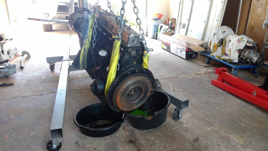 I then removed the flywheel and attached the engine stand’s mount to the backplate of the engine using grade 8 high-tensile fittings… 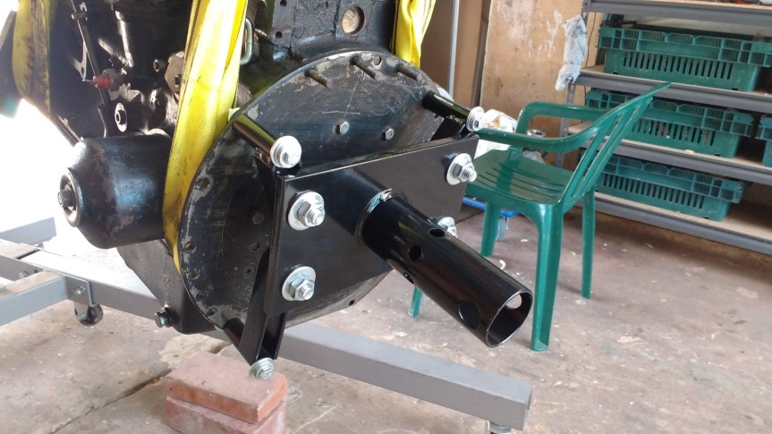 …before lifting the whole assembly and fitting it onto the engine stand… 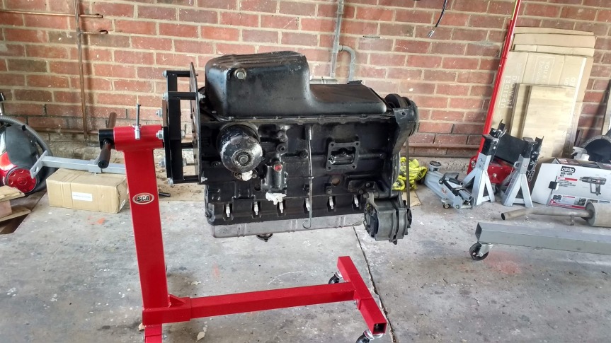 So far so good – it hasn’t fallen off yet despite me giving it a really good wobble before unhooking the crane. It’s just a cheap and cheerful stand from Super Cheap Auto but it’s rated at 450kg and seems to be doing its job well. It’s a little stiff to turn over single-handedly but it’s not impossible, even for a skinny-armed guy like me. Hopefully the back plate won’t get bent with the weight of the engine hanging from it but I’ll check it with a straight edge when it comes off and swap it over for a spare if there’s any doubt. With the engine spun over on the stand whipping the sump off was easy – it looks fairly good in there on first inspection and isn’t too sludgy… 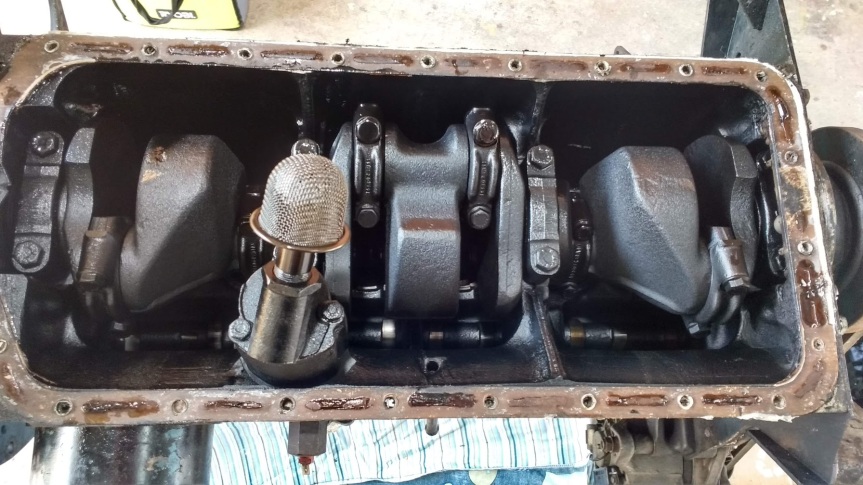 My first port of call was the thrust washers – there are two on the 2500 engine, either side of the fourth main journal of the crank. Whilst the end float was measured to be within spec at about 0.006″, the problem here was obvious – one (the front-most, which takes most of the load when the clutch is depressed) had started to break up. The crank bearing faces seem to be OK – there was some very light scoring to the front-most one where the bearing has broken up, but nothing that was able to be felt with a fingernail. Both of the existing thrusts are standard size so when rebuilding I’ll experiment with adding one oversized one to the mix to try to bring the end float down to the lower end of the tolerance range. 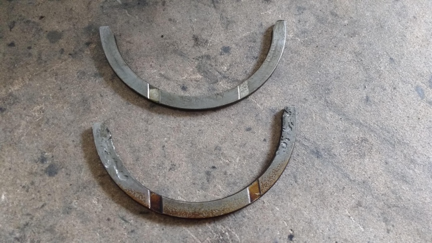 Taking off the main bearing caps for inspection produced some mixed results – the bearing shells themselves are aluminium-tin which do not show any copper as a wear guide but they looked generally OK, if not a little tired with some light scoring in places… 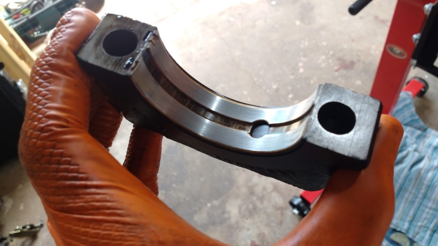 The crank journals themselves also looked passable – again some light scoring but nothing that could be felt with a fingernail. At this point it looked as though a new set of standard size bearing shells might be all that was needed to inject a good few more years of life into the lump… 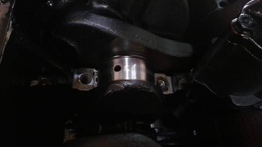 Sadly the big ends were a different story – both the bearing shells and the crank journals had deeper scoring than on the mains with undulations able to be felt with a fingernail on most of the journals… 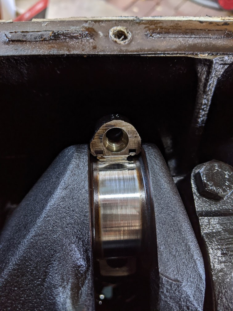 …whilst the bearing shells weren’t in much better shape either… 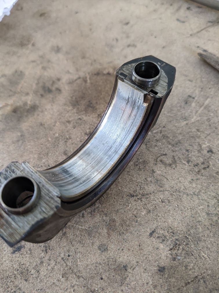 So at this stage my simple refresh had grown in scale from chucking in some new bearing shells to including a crank regrind. Seeing as I was now edging into rebuild territory it got me wondering how far to go with the engine work. I saw my options as follows: 1) Do the bare minimum – chuck in new bearing shells and thrusts and reassemble as-is. It’ll probably go on happily for years given the fairly light use it will get from me. 2) Do a half-arsed job – get the crank ground and fit new bearing shells and thrusts. Leave the block as-is. 3) Go full monty – strip it down completely, get the crank ground and the block re-honed/re-bored with new bearing shells, thrusts, rings and/or pistons as necessary. In hindsight I’m kicking myself for not carrying out a compression test on the engine whilst it was up and running in the parts car – but the unexpected arrival of this car and the need to remove the other one from my driveway as quickly as possible unfortunately meant this wasn’t the best use of my time. In order to get some sort of idea of the condition of the bores and rings, prior to removing the head for a visual inspection I decided to run a leak-down test on the engine. I acknowledge that the results of such a test might not be 100% accurate given that a) the engine hasn’t run for a while and b) the test is ideally carried out on a warm engine, but given the circumstances I decided it was better than nothing. Four out of the six cylinders showed a leakage at around the 50% mark (not so good), with cylinders five and six showing a lower figure of around 30%. Given the fact that the engine’s been upside down on the stand for a week now and only cylinders 5 and 6 show any oil dripping out of the spark plug holes I suspect this is more to do with oil passing through the rings from below and improving the results for these two cylinders as opposed to them being less worn than the other four (i.e. essentially the results show the difference between a wet test and a dry one). 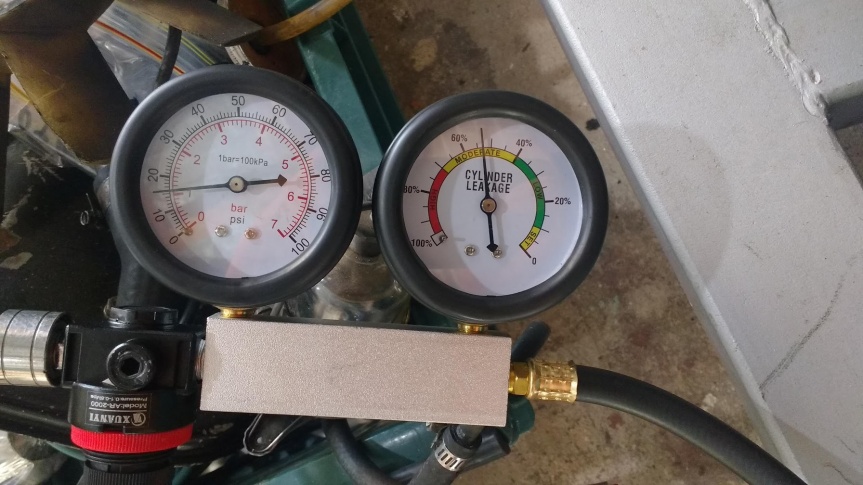 Given the obvious hisses coming from both the dipstick and, more prominently, around the cam followers I came to the conclusion that the air was escaping past the piston rings – either due to worn/stuck rings and or worn bores. Ideally I’d put the engine in the car, run it for a while (including giving it a couple of good Italian tune-ups) and then carry out compression and leak-down tests to get a more accurate idea of its condition. However, the thought of putting it all back together again only to potentially have to take it all apart again in a few weeks fills me with dread. I’d quite like to drive the thing. So this leaves me thinking that the best (albeit most expensive) course of action is to go full monty on this bad boy – strip the block down, get the crank ground and the cylinders honed or bored as needed. Fit new pistons and/or rings, new bearing shells and thrusts, a few new seals and gaskets etc. Given the fact that it will be mated to a rebuilt gearbox it should mean the drivetrain will be largely sorted for the foreseeable future. I’ll have a look at the cam shaft when the block’s stripped and make a decision about that at the time, the same goes for the oil pump. I’ll also have a think about the head – worst case scenario I can clean it up, give the valves a quick lap and run it as-is for now with a view to getting it rebuilt with hardened valve seats when funds eventually allow. But then again my mission has had a habit of creeping slightly of late… |
| |
Last Edit: Aug 26, 2020 2:24:49 GMT by llessur
|
|
|
|
biturbo228
Posted a lot
  
Posts: 1,868
Member is Online
|
|
|
|
|
Often the case on these engines that there's bits and pieces that need doing, if anything just due to the age of them.
They're dead easy to rebuild though. Might be worth trying to get hold of Kas Kastner's performance rebuild book for some tips on these. Not that you're necessarily looking to get big power out of it, but half of the book is just about what you need to do to keep these engines together for a race weekend at 200bhp which is all stuff that will help the longevity of a standard engine. The main thing that I remeber is drilling out the oil gallery going to the centre two crank bearings 1 size up to improve flow to them as they're feeding two rods each rather than 1.
All this stuff I learnt after I built mine so I think it's coming apart again at some point so I can improve it!
|
| |
|
|
|
|
|
|
|
|
|
Might be worth trying to get hold of Kas Kastner's performance rebuild book for some tips on these. Not that you're necessarily looking to get big power out of it, but half of the book is just about what you need to do to keep these engines together for a race weekend at 200bhp which is all stuff that will help the longevity of a standard engine. The main thing that I remeber is drilling out the oil gallery going to the centre two crank bearings 1 size up to improve flow to them as they're feeding two rods each rather than 1. Great suggestion thanks! I've bought an e-copy and sneakily printed and bound at work... |
| |
Last Edit: Aug 31, 2020 2:24:12 GMT by llessur
|
|
|
|
|
Aug 31, 2020 19:37:58 GMT
|
Triumph 6s die slow, but that one looks to have already had a freshen up at some point and it's probably ready for a more complete rebuild now. My advice would be not to skimp on the major rotating/reciprocating unit. Get the cranl ground and fit matching shells, and, unles the bores are really good enough for a hone and re-ring - spend the extra for a rebore and new pistons. I skipped that part on my recent GT6 engine rebuild and has issues (epic oil burning for first few hundred miles and still rather too much going that way plus some odd noises). Also I suggest a simple alternative way of hanging the engine on a stand that is a bit less scary, won't bend your backplate and allows full dismantling and assembly 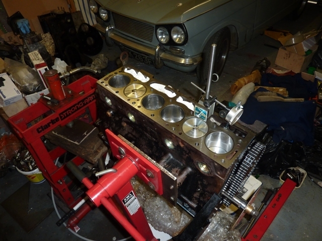 |
| |
1967 Triumph Vitesse convertible (old friend)
1996 Audi A6 2.5 TDI Avant (still durability testing)
1972 GT6 Mk3 (Restored after loong rest & getting the hang of being a car again)
|
|
|
|
|
|
|
Much to the wife's dismay, I have taken the opportunity provided by the weekend to lock myself away in the garage poking over my partially-dismantled engine and coming up with a plan of action which balances my desire for a solid, functioning power unit with the fact that I don’t want to spend obscene amount of money in the process. In order to completely assess the situation I continued the strip-down, starting with the removal of the rocker gear: 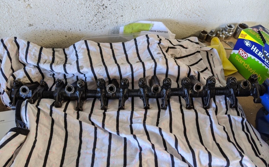 ...pushrods...  ...and finally the head. By all accounts this could have gone one of two ways for me – either lifting straight off or putting up a week-long fight which would involve heat, WD40, various pulling contraptions and lots of naughty words. In the end I was lucky as with a couple of moderate taps from a mallet against a block of wood it came free. At this stage I also removed the cam followers, storing each in a separate, labelled bag to ensure they can be returned whence they came. 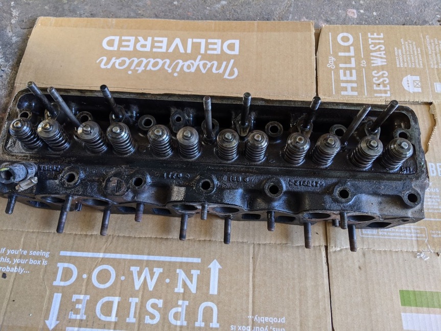 The head itself is a bit of an unknown quantity at this stage – it’s certainly a bit coked up and will at best need a strip down, clean and reassembly but I’ll make further judgement on this a little later down the track. Hopefully there is no cracking between the valve seats. It may be that after doing the rest of the engine work I want to send the head to a professional for attention but I’ll see what the budget looks like when we get there. If the worst comes to the worst and I’m poor and miserable then I can use it as-is in the interim and attend to it some time after the engine has been refitted. 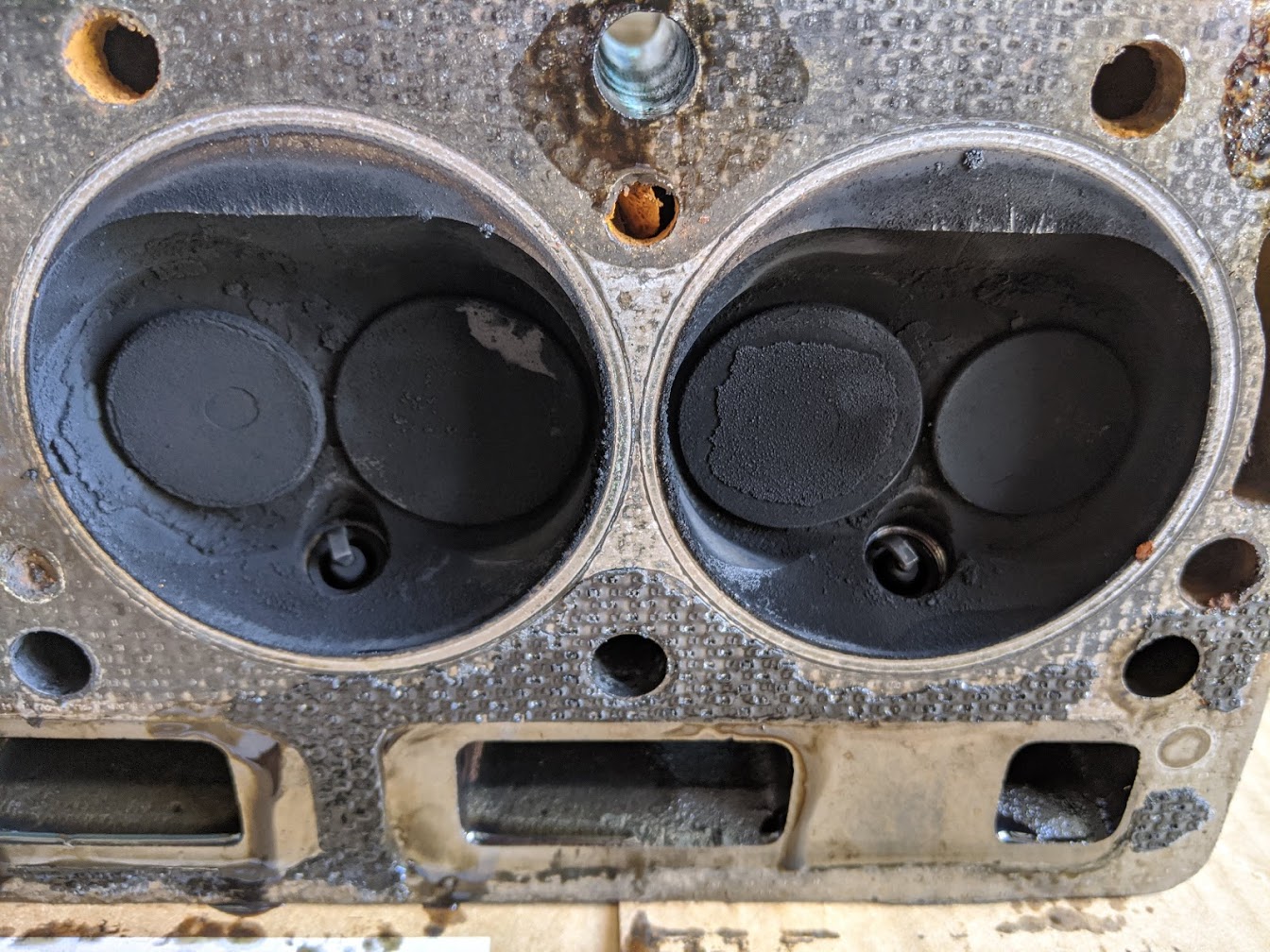 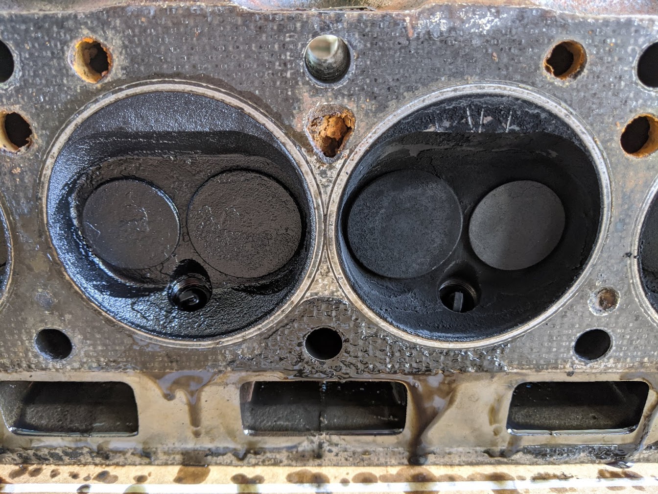 Incidentally, the head is part number 219021 which is identical (except for the EGR port being drilled for the Australian market) to the 219016 head which is apparently considered to give the best inlet flows of any of the standard Triumph 2.5 heads. So that's nice. As fun as contemplating head work was, the block would be the ultimate decider in the level of work that would need to go into the engine. I was hoping that the bores would be in good enough condition for only a hone to be necessary but sadly that didn’t look like it would be the case – a couple of them having noticeable vertical scoring meaning that a full re-bore would be on the cards. 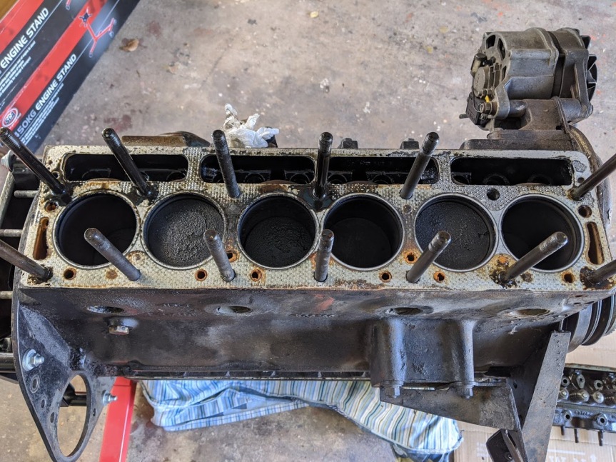 Number 6 was the worst of the bunch... 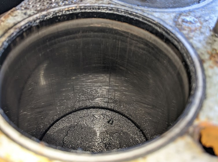 Followed by number 3, on the right of the below picture: 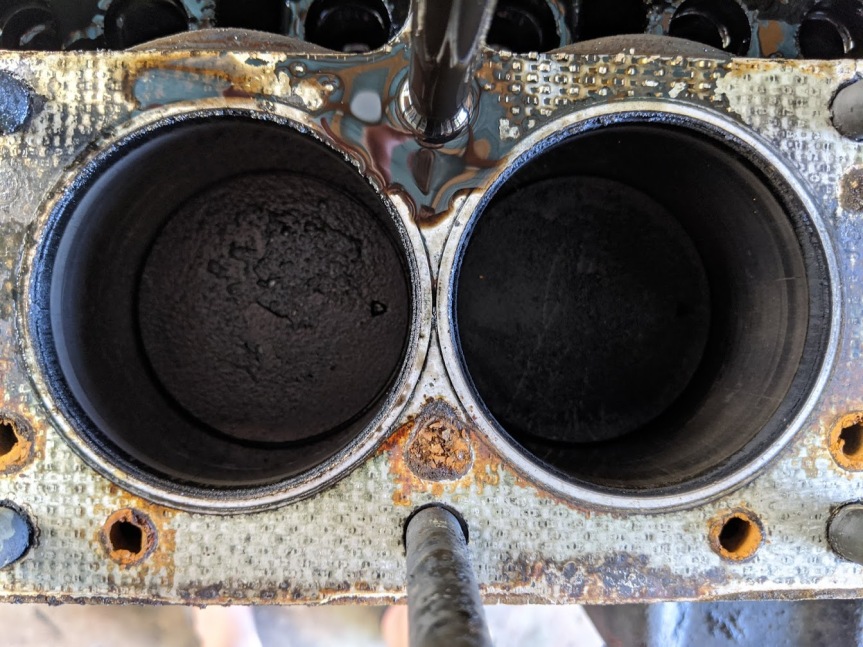 At least this has helped me decide on what needs to be done in terms of machining – I’ll get the block re-bored and decked if necessary as well as having the main and big end crank journals ground. Hopefully I can get away with 0.020″ oversize on the bores and 0.010″ undersized on the crank but I’ll get it inspected by the machine shop before ordering any bearings and pistons in case we need to go one size further on any of those. The only other unknown with the block at this stage was the condition of the camshaft. After a fairly uneventful removal process it seems the camshaft in my engine is part number 307621 which is the stock-standard cam for the 2500 TC and S. It’s in fair condition considering its age, although does have light wear marks to some of the lobes and bearing surfaces, as well as some very minor pitting to two of the lobe tips. Its condition annoys me somewhat as it falls into the territory of neither being completely buggered or in perfect condition. My heart says if I’m going to the trouble of rebuilding the rest of the engine I should replace it, whereas my head is telling me to save the money and reuse it. Stupid boring head. 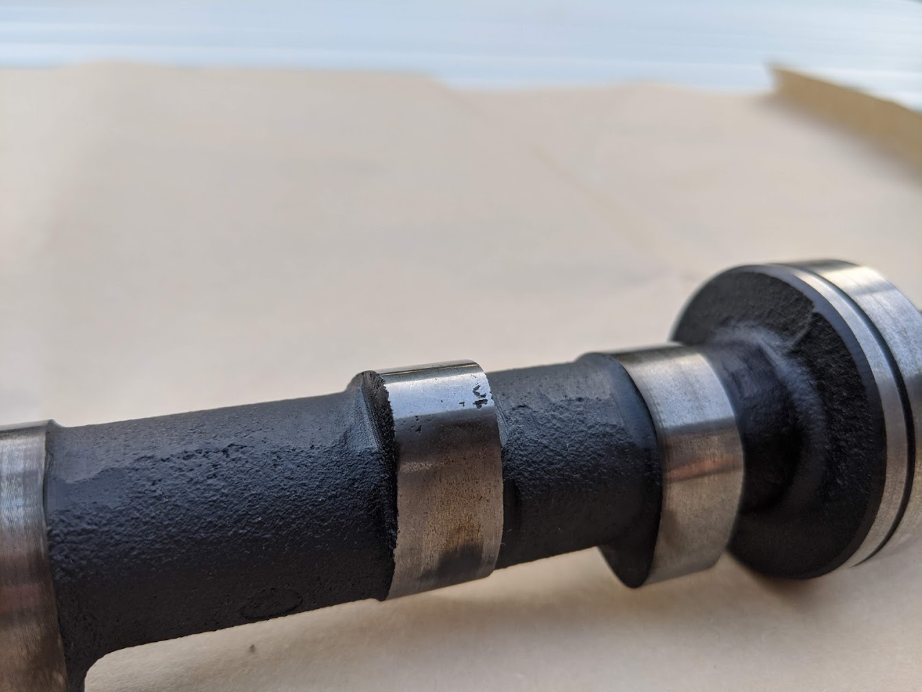 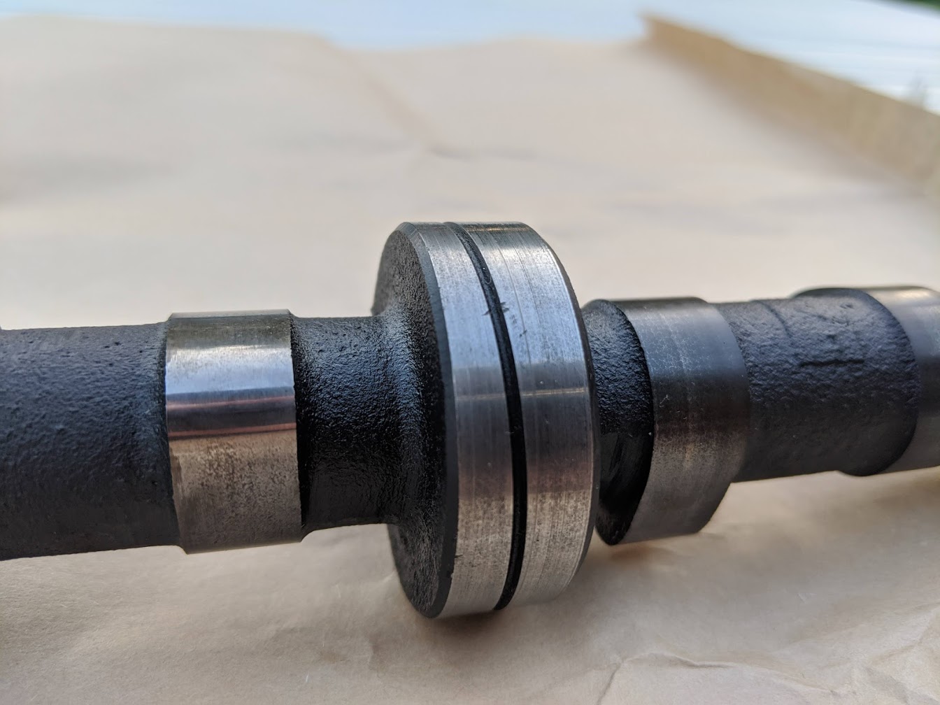 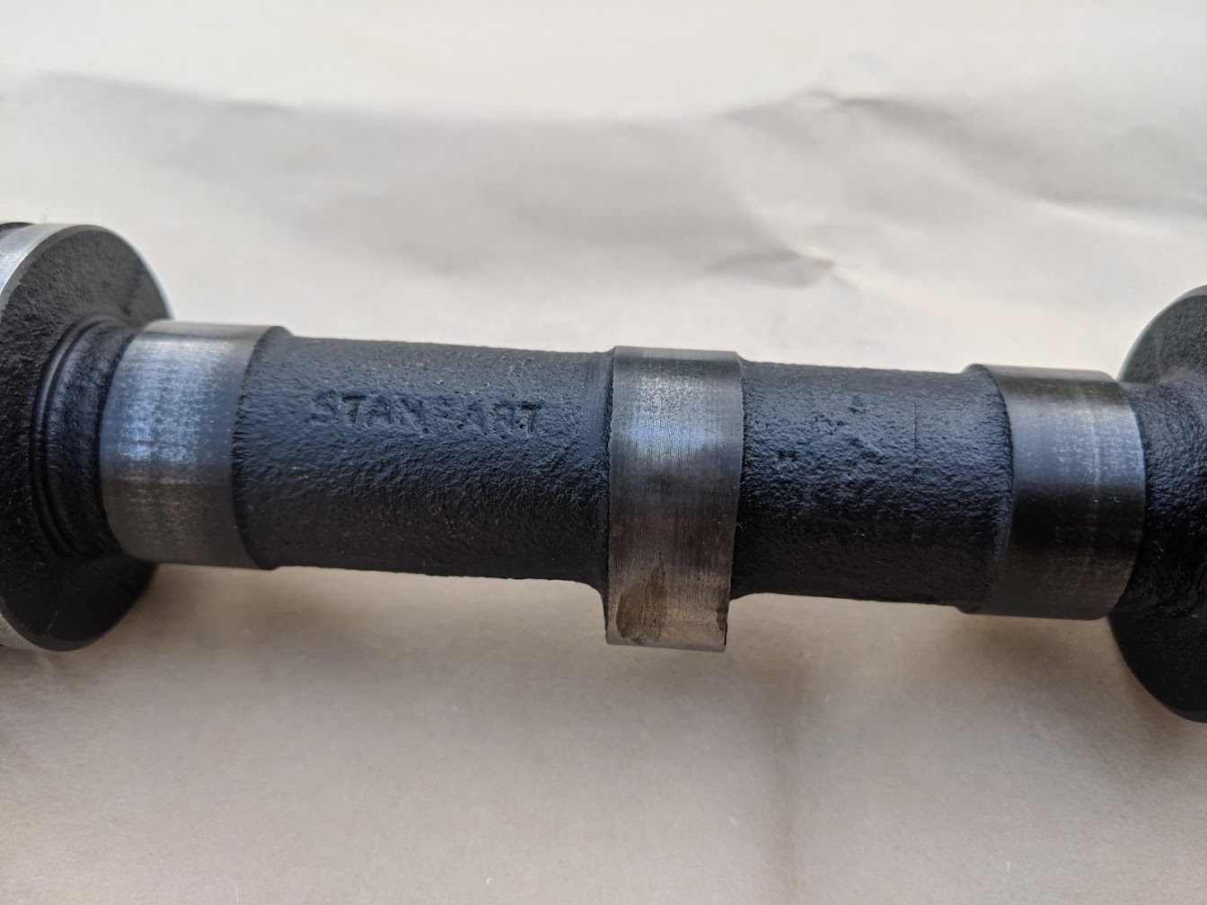 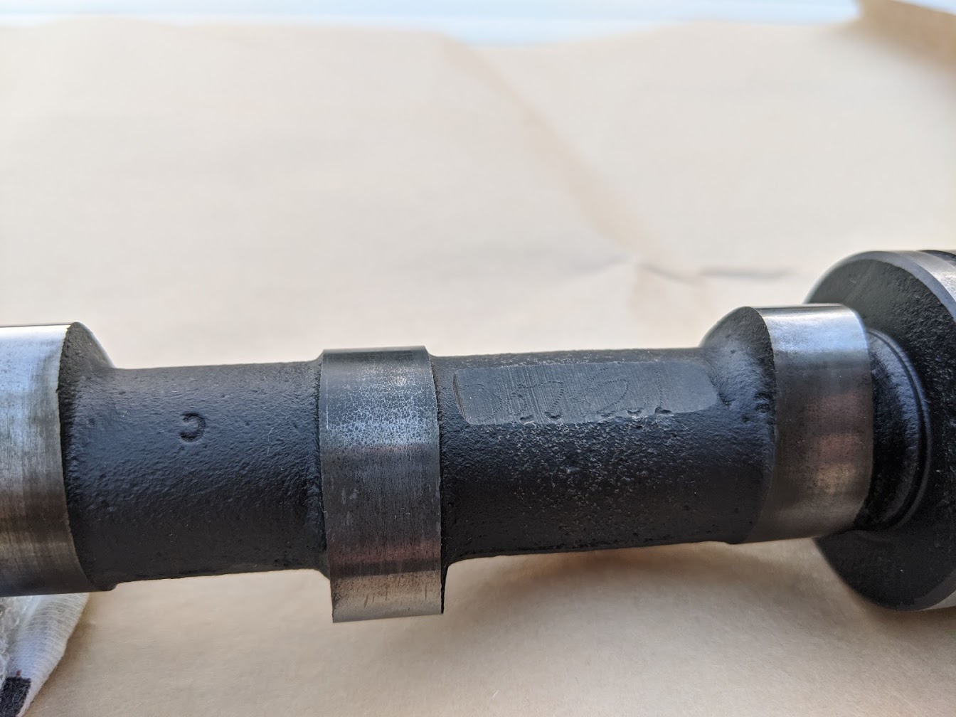 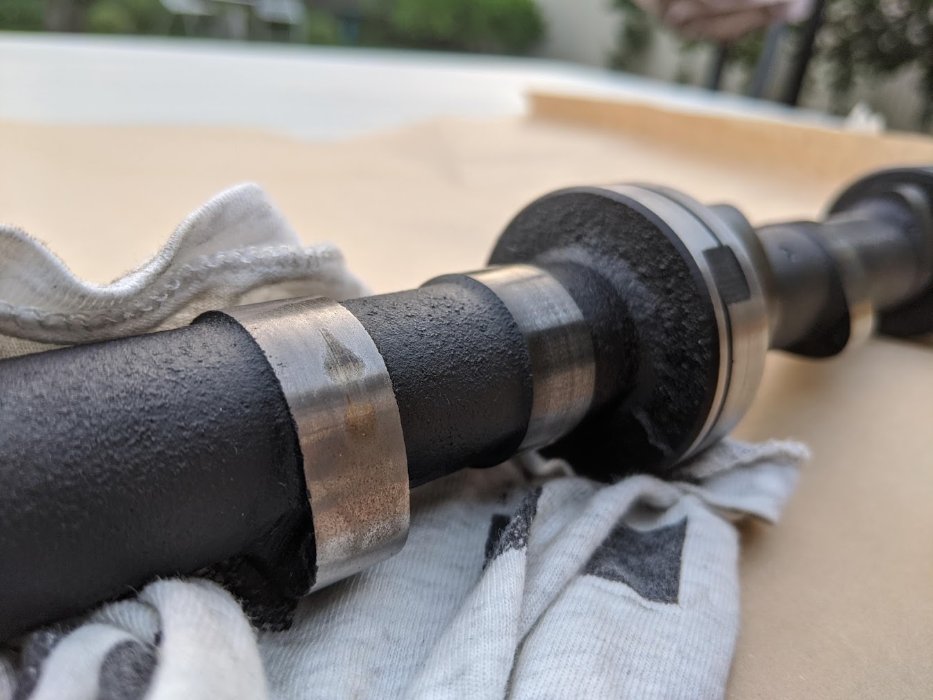 If I were to replace the camshaft there are various options including the 2.5PI standard item (part number 308778) which seems to be one of the most popular choices of OEM Stanpart cams for improving mid-range power without adversely affecting low-end torque. Chris Witor also does a reprofiled higher inlet lift variant of this camshaft which promises to get the most out of the twin HS6 carbs (especially when combined with a slight skim to the head to increase the compression ratio to 9:1), but this isn’t a cheap option at $700/£350. Newman Cams may also be able to grind this profile from a blank for less so I’ll follow that up with them as well. But, I’m also mindful that straying away from a stock cam could easily open the door for more expense which I can’t really afford such as a gas-flowed head, 6-3-1 manifold with sports exhaust, 123ignition with an ignition profile to better suit the cam etc etc. For now there are just the pistons and crank left to remove to complete the strip down, as well as a few other odds and sods such as the engine front and back plates etc. Then I’ll do some research into stocking up with rebuild parts and tracking down a decent local machine shop where the wallet-emptying fun can really begin… |
| |
Last Edit: Sept 1, 2020 6:12:46 GMT by llessur
|
|
|
|
|
|
|
Triumph 6s die slow, but that one looks to have already had a freshen up at some point and it's probably ready for a more complete rebuild now. My advice would be not to skimp on the major rotating/reciprocating unit. Get the cranl ground and fit matching shells, and, unles the bores are really good enough for a hone and re-ring - spend the extra for a rebore and new pistons. I skipped that part on my recent GT6 engine rebuild and has issues (epic oil burning for first few hundred miles and still rather too much going that way plus some odd noises). Also I suggest a simple alternative way of hanging the engine on a stand that is a bit less scary, won't bend your backplate and allows full dismantling and assembly I reckon it's heading that way based on the condition of the bores. I've had a quote for getting the work done which isn't too bad - then there's around $500 (or 250 pounds) of parts - pistons & rings, bearing shells, timing chain and sprockets etc. Still don't know what to do about the camshaft - I'll be doing really limited miles so very tempted to leave it as-is for now. I suspect the pitting is more likely casting imperfections as opposed to wear. I can always swap this out for a new one later if I need to. How was your cam? I like the mounting option btw - I'd read that somewhere else too but didn't have the thick piece of steel plate to hand when I set about stripping it down. Will sort it out for reassembly. |
| |
|
|
|
|
|
|
|
|
308778 cam with or without the extra lift is a worthwhile upgrade on what you have. You could also consider a Newman PH1.
My old PI made just under 150bhp with a wonderfully long and flat torque curve using a standard 308778 cam, diy gas flowed head, TR6 cast exhaust manifold with twin down pipes and EFI using the original inlet arrangement.
Nick
|
| |
1967 Triumph Vitesse convertible (old friend)
1996 Audi A6 2.5 TDI Avant (still durability testing)
1972 GT6 Mk3 (Restored after loong rest & getting the hang of being a car again)
|
|
biturbo228
Posted a lot
  
Posts: 1,868
Member is Online
|
|
Sept 1, 2020 10:13:30 GMT
|
If you can wait long enough I'll have an early PI cam going. I've got another to go in my engine before it's started, although it's got unequal inlet and exhaust timings which these engines don't seem to like. Oh, and if vitesseefi's 150bhp for a 2.5PI with a gas flowed head and EFI doesn't sound like much compared to the standard PI (rated as 150bhp), it's worth noting that the 150bhp stock figure is gross bhp. Triumph wasn't as cheeky as some US manufacturers with gross figures, but it was higher than the net 141bhp these engines produce in the car. Still, better than the 135bhp net of the Datsun 240z  |
| |
|
|
|
|
|
Sept 1, 2020 12:55:20 GMT
|
|
Why do you say these engines don’t like asymmetrical timing? I have a hybrid Newman PH3 (inlet)/PH2 (exhaust) in my current Vitesse engine and that works just fine. Don’t have a bhp number as it’s never been on a synonym but it pulls hard from 2,800 and is very docile and tractable below that.
Wouldn’t recommend for twin carb use - it’s too wild (inlet duration 300 deg, exhaust 280 deg). Needs a throttle per pot really - does have some minor reversion issues on my plenum Inlet EFI setup which make it a bit trying in extended stop/start traffic, though apparently not enough to force me to sort it (5 years /18kmiles)
Nick
|
| |
1967 Triumph Vitesse convertible (old friend)
1996 Audi A6 2.5 TDI Avant (still durability testing)
1972 GT6 Mk3 (Restored after loong rest & getting the hang of being a car again)
|
|
biturbo228
Posted a lot
  
Posts: 1,868
Member is Online
|
|
Sept 1, 2020 13:24:02 GMT
|
Huh, interesting. It was one of those things I'd read about tuning with the original PI that I'd just assumed was something to do with the head design. If it does work well then I'm happy to be able to keep my new hot cam! The one I've got is a TriumphTune Sprint 90 which is 39-71-81-29 and 290 deg inlet duration. Think I'll see what I can make of it  |
| |
|
|
jamesd1972
Club Retro Rides Member
Posts: 2,921  Club RR Member Number: 40
|
1977 Triumph 2500Sjamesd1972
@jamesd1972
Club Retro Rides Member 40
|
Sept 1, 2020 14:50:08 GMT
|
Nice write up and progress, for future reference one thing I've found doing hubs on the LR is that the shell in the freezer and the hub in the oven at 100deg can get things to go together with little or no whacking... 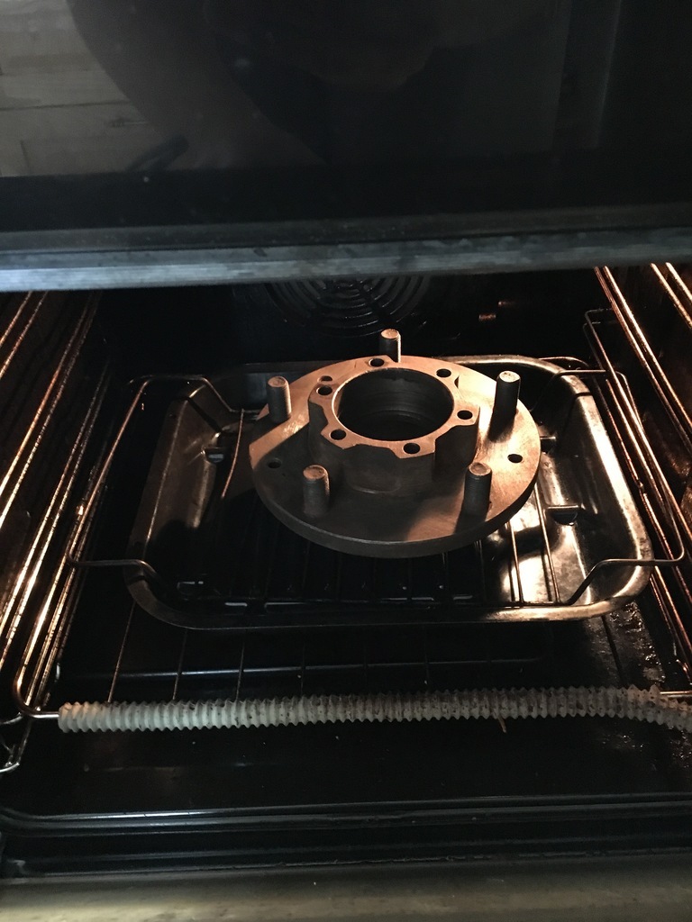 Just don't get caught by the wife whilst doing this... Good luck with the engine re-build, these are a sweet lump when running well. James. |
| |
|
|
|
|
|
|
|
|
Meant to say before....... the pits shown near the lobe peak on your first cam photo mean the cam is on the way out. Should be no pits on the working surfaces. You can also measure the heel to peak distances for all lobes and compare them. They should be all the same on a standard cam. They rarely are on a used one, even when they look ok.
Follower condition is also very important. Light circular markings on the flat face are normal but it should be flat. Any dishing indicates significant wear as does pitting or a a diametric wipe mark or score showing the follower has stopped turning.
Old followers in good condition may be reused with the same cam in the same block provided they are returned to their original position.
Be wary of new followers. These are flat tappet engines and flat means flat...... not CROWNed. Even those who should know better have been known to supply CROWNed...... so check!
Nick
|
| |
1967 Triumph Vitesse convertible (old friend)
1996 Audi A6 2.5 TDI Avant (still durability testing)
1972 GT6 Mk3 (Restored after loong rest & getting the hang of being a car again)
|
|
|
|


