lebowski
Part of things
  Hillman Avenger, Clan Clover
Posts: 488
|
|
|
|
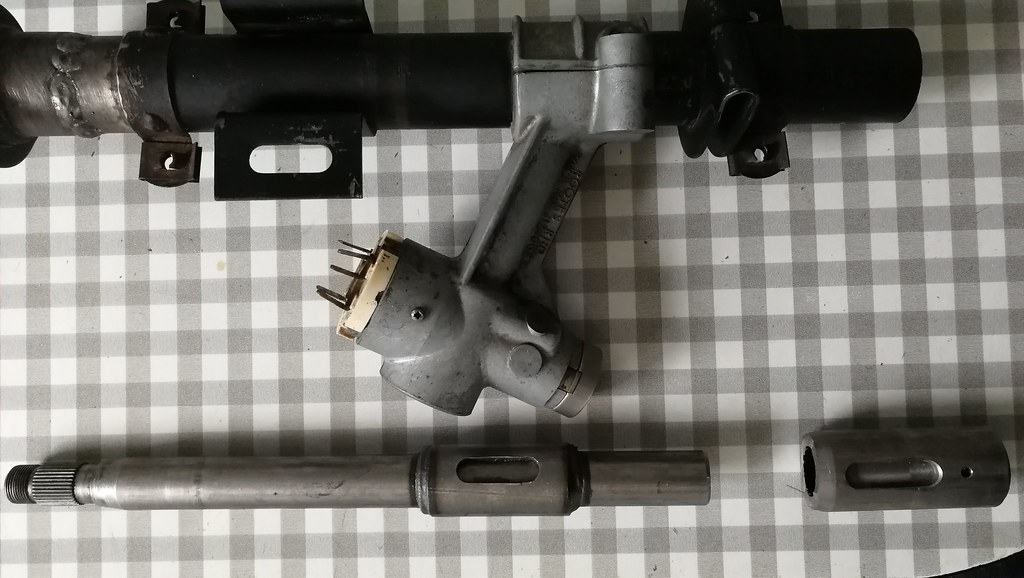
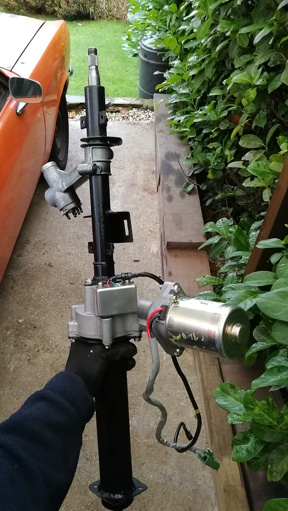
I've been fitting electric power steering to the Avenger over the last few weeks. The steering at parking speeds is ridiculously heavy with the quick rack and smaller diameter steering wheel, plus the wider tyres. I got hold of an EPS column from a Corsa B Once stripped down it looks like this. The steering wheel spline is the same as the early Avenger. Unfortunately though, the shaft is too short so needs modifying anyway.
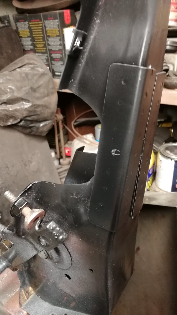
By far the most difficult part of fitting this motor into the Avenger column is deciding how far along the column it should sit. Space is really tight in the footwell/pedal box area and some time consuming trial and error was required. It's necessary to remove a semi circular area of the pedal box to give clearance to the motor, otherwise it's impossible to lift the column high enough in the car. I took this cutout right back to the captive nuts for the stop light switch bracket.
I actually had to remove a little more after this photo was taken, literally right upto the captive nut.
The Avenger/Sunbeam steering shaft is 769mm long, so the new column total length needs to be the same.
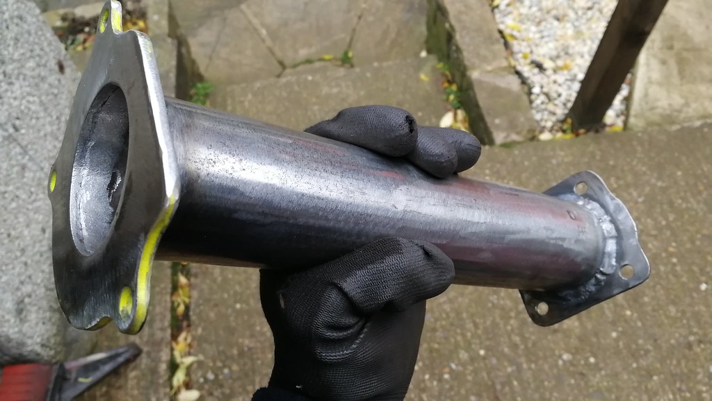
The Corsa UJ can be split with a mallet easily. It has a DD (double D) connection. The lower part of the Avenger steering shaft was cut to length and then ground into a DD shape at one end so it's a tight fit into the UJ. I then made an outer piece by joining the original Corsa flange with some 2.25" exhaust pipe. I sleeved it down at the bottom end for a 3/4" ID/2" OD sealed bearing, and welded in a smaller section of pipe to act as a bearing stop. The end was then peened over in a couple of places to retain the bearing. The plate that bolts to the floor needs tacking on when the column is fitted in the car, as it doesn't sit perpendicular on the pipe.
The hole in the floor is already big enough for this pipe to fit through.
|
| |
|
|
|
|
lebowski
Part of things
  Hillman Avenger, Clan Clover
Posts: 488
|
|
|
|
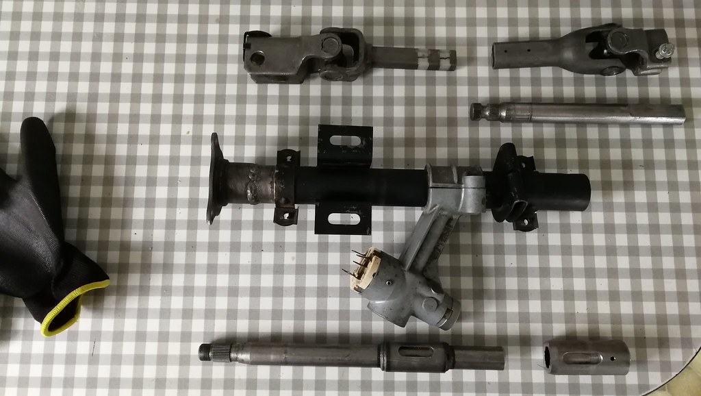
The upper part of the column is a little more difficult. The Avenger shaft needs cutting to length and the splined joiner needs removing from the Corsa shaft (see bottom right below). This part has a spline inside for about 30mm, and the rest is a plain bore. Unfortunately the Avenger shaft doesn't fit inside this bore, so a lathe is needed to match the two diameters, and then the parts need welding together.
It's important that this part is a good weld, because if it fails you'll have no steering. I outsourced the welding to someone with a powerful welder. The outer column is simply a case of joining the Corsa and Avenger columns together at the right length. I actually made the upper column 20mm too long, which means the steering wheel will sit a little closer to me. If I don't like it I'll have to remake the upper column. Components ready to be assembled.
And the finished product.
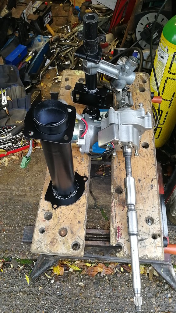
Fitted in the car it looks like this... I also beefed up the pedal box as it was a little flimsy after making the cutout. I made this bracket to support the motor, as it's fairly heavy and will be sending its torque into the chassis. I'll replace the jubilee clip with a more substantial one.
I haven't tested it yet. I still have to finish assembling everything and then deal with the electrics. |
| |
|
|
|
|
|
Dec 20, 2019 11:47:43 GMT
|
|
Neat job you've made there.
Don't under estimate the torque these can put into the vehicle structure, it surprised me when I did mine.
|
| |
Proton Jumbuck-deceased :-(
2005 Kia Sorento the parts hauling heap
V8 Humber Hawk
1948 Standard12 pickup SOLD
1953 Pop build (wifey's BIVA build).
|
|
|
|
|
Dec 20, 2019 12:01:53 GMT
|
|
looks a well engineered solution, wise decision to farm out the column welding I would do the same.
|
| |
|
|
|
|
|
Dec 20, 2019 15:21:45 GMT
|
|
Does the EPS require any sort of control unit or input from a speed sensor, or is it 100% self-contained?
High-grade project BTW...beyond what many of us can do (speaking for myself). Your Dad must be a great teacher. John
|
| |
|
|
lebowski
Part of things
  Hillman Avenger, Clan Clover
Posts: 488
|
|
|
|
I have finished with the power steering. The Corsa EPS unit has it's own ecu to control it. The steering ecu expects to see a speed signal, which allows it to alter the assistance between high, medium and low assistance automatically based on the speed that the car is travelling. I'm not sure exactly where the Corsa gets this signal from (could be from the rev counter, a reluctance ring, speedo etc.). The power steering won't work without some kind of speed signal.
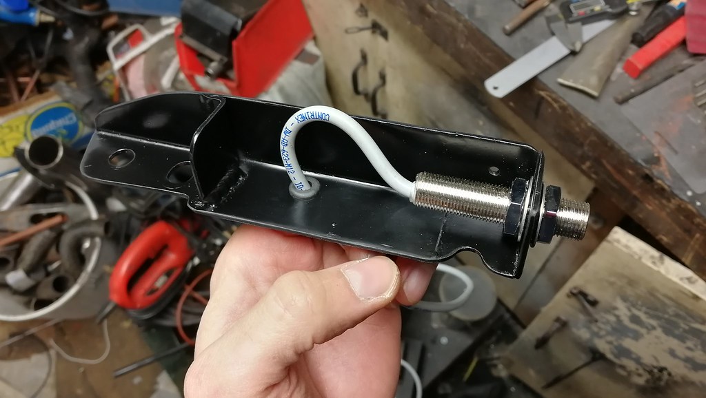
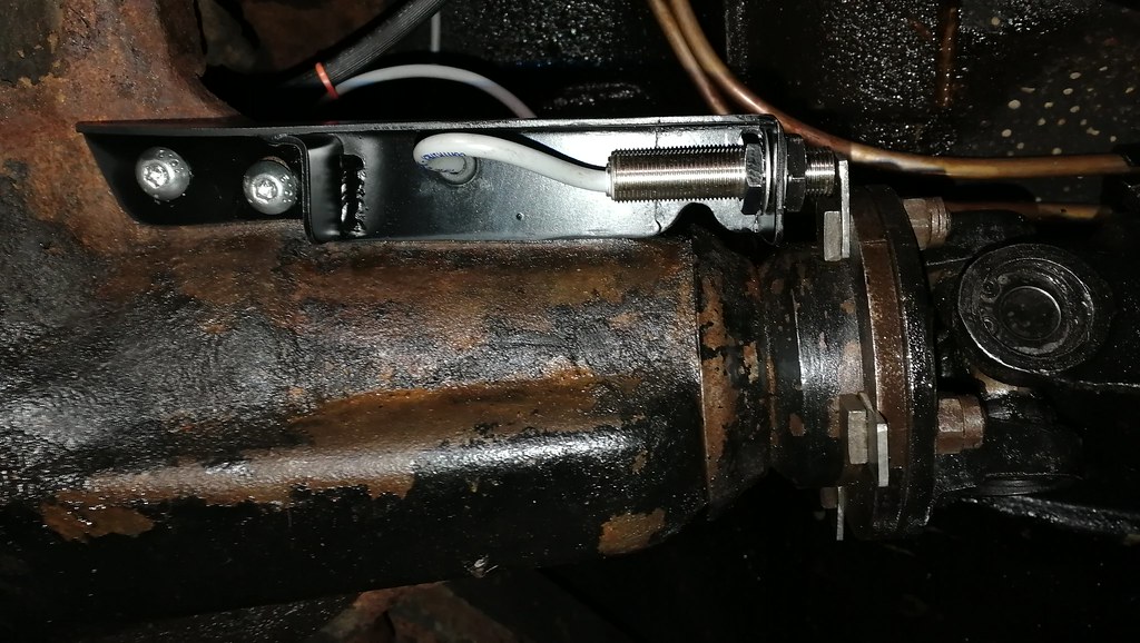
Most aftermarket installs use a potentiometer based system which creates a pulse and fools the ecu to provide a fixed assistance based on the pot position. I'm sure these systems work fine and they are cheap, but I wanted to have the variable assistance as per the original Corsa, as my steering is super heavy at parking speeds but could be too light at high speed if a lot of assistance is used. In the end I bought a speed sensitive system from Easysteer for £150. This uses a proximity sensor pointed at something to provide the speed pulses, so the steering will work as Vauxhall intended. There are no doubt several options to mount the proximity sensor, but I made this bracket which bolts to the diff housing. I drilled and tapped 2 M8 holes in the axle web to mount the bracket. I originally wanted to point the sensor at the heads of the prop bolts, but I'm not sure it's possible due to the shape of the axle nose, so I made 4 tabs which fit under the prop bolts and give the sensor something to aim at.
I then ran the cable up into the boot where I have several other cables. I made a blanking plate to mount the steering ecu in place of the ashtray. I didn't really want to lose the ashtray but it's getting pretty congested behind my dashboard. The plate has four tabs perpendicular to the main surface, which bolt to the sides of the ecu.
I've mounted the Easysteer control box in the glovebox next to my fuse and relay boxes. The system allows you to program the assistance change points, so I'll still need to do that. I did briefly start the car and I could turn lock to lock easily with one hand, which definately wasn't possible before. |
| |
|
|
lebowski
Part of things
  Hillman Avenger, Clan Clover
Posts: 488
|
|
|
|
This picture shows the control box that comes with the Easysteer unit (on the right). The green button I've wired in is used to program the unit. It basically involves driving at the speed/s you wish the assistance levels to decrease and then holding down the button for a few seconds.  IMG_20191130_145518 IMG_20191130_145518 by Chris Witkowski, on Flickr |
| |
|
|
|
|
|
Dec 23, 2019 17:53:38 GMT
|
|
Fair play, you certainly aren't cutting any corners with this build, not even on the smaller items.
Keep up the great work, really enjoying following this.
Will
|
| |
1964 Saab 96 two Stroke
1971 Hillman Avenger 1500 GL (Tuned 1600 fitted)
1976 Saab 99 2dr EMS (Project of very slow progress)
1978 Saab 99 2dr EMS (Awaiting reshell)
1981 Saab 99 2dr Turbo (Awaiting reshell)
|
|
lebowski
Part of things
  Hillman Avenger, Clan Clover
Posts: 488
|
|
|
|
|
Thanks Will. The thread is up to date now, so the updates will slow down somewhat.
|
| |
Last Edit: Dec 24, 2019 7:03:24 GMT by lebowski
|
|
lebowski
Part of things
  Hillman Avenger, Clan Clover
Posts: 488
|
|
Jan 19, 2020 15:36:15 GMT
|
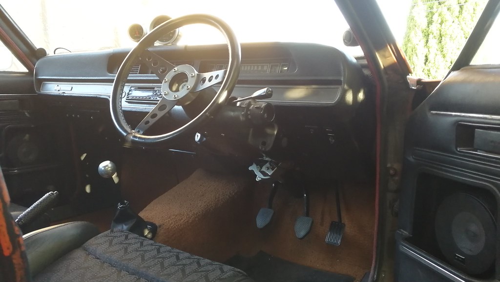
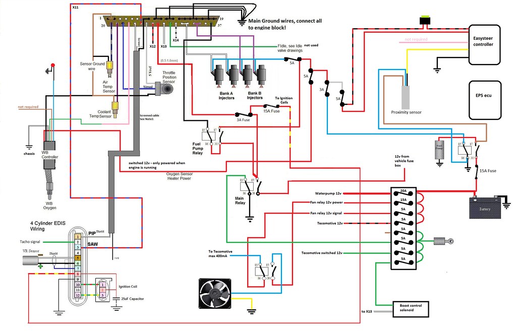
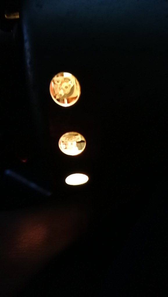
Not much has happened on the Avenger lately. I spent most of November, December and January overseas. Before I left, I got the power steering working. It made a huge difference and the super heavy steering is now about as light as a modern car. The EPS column is also very discreet under the dash, and can only really be noticed from underneath. The wiring for the EPS ecu was as below: One thing I did manage to get done is to sort out the rev counter. The car has been fitted with a Yazaki one for a year or so. It's triggered directly from the edis module pin 2 (see above). Of 7 or 8 Smiths, Jaeger and Autometer tacho's I tried, the only one that would work directly from edis was the Yazaki, so I went with that one. Unfortunately it's a bit hit and miss getting rev counters to work with edis. It only outputs a 12v square wave which is not enough to trigger many tacho's which normally work from the coil negative. Unfortunately for me, the Yazaki rev counter wasn't accurate. It was over 1000rpm out at high revs according to the laptop hooked up to the megasquirt. I did waste some time building a diode based circuit to try and combine the signals from the two sides of the coil, with the aim of using a different, more accurate tacho. Unfortunately this didn't seem to work with any of the ones I had available. I removed the tacho and stripped it down, hoping it would have some calibration function inside. Luckily for me, it does have a couple of potentiometers, which once lubed up were free to move. This is one of them viewed through a hole in the side of the casing. With a little time spent, I now have a rev counter which is bang on. |
| |
|
|
|
|
|
|
|
Jan 19, 2020 16:34:09 GMT
|
|
Very cool indeed. John
|
| |
|
|
|
|
|
Jan 19, 2020 21:49:10 GMT
|
|
Having fought the EDIS / tacho battle a couple of times I found that in order to get the voltage sensing RVC type to work from the EDIS diagnostic output, I had to build a little coil emulator amplifier which has been working on my Vitesse for 15 years now. When I converted by 2.5 PI, that was fitted with an RVI current sensing type as standard and I found that by using the standard coil supply wire to power the coil pack the tacho worked as normal without any further mods.
Liking your power-column mod. Very nicely engineered
Nick
|
| |
1967 Triumph Vitesse convertible (old friend)
1996 Audi A6 2.5 TDI Avant (still durability testing)
1972 GT6 Mk3 (Restored after loong rest & getting the hang of being a car again)
|
|
lebowski
Part of things
  Hillman Avenger, Clan Clover
Posts: 488
|
|
|
|
|
Thanks gents. I think my next choice would have been to buy a small circuit board from a company like Spiyda, which basically bypasses the circuitry inside the tacho and allows it to be triggered from a 5v or 12v signal, as well as giving calibration trim options too.
I know there are techniques like you mention above Nick, plus the 3 diodes method, but even they seem hit and miss, and I didn't want to start cutting into my wiring loom to test them all.
|
| |
|
|
|
|
|
Jan 20, 2020 21:31:10 GMT
|
|
Smiths RVI current sensing type with the coil supply passing though it should be easy and reliable. I know several other Triumph EFI folks who’ve learned from my battle and gone that way successfully. Just wish I’d worked it out before I did the Vitesse. - would have saved a lot of fooling about......
Nick
|
| |
1967 Triumph Vitesse convertible (old friend)
1996 Audi A6 2.5 TDI Avant (still durability testing)
1972 GT6 Mk3 (Restored after loong rest & getting the hang of being a car again)
|
|
lebowski
Part of things
  Hillman Avenger, Clan Clover
Posts: 488
|
|
Feb 29, 2020 17:32:49 GMT
|
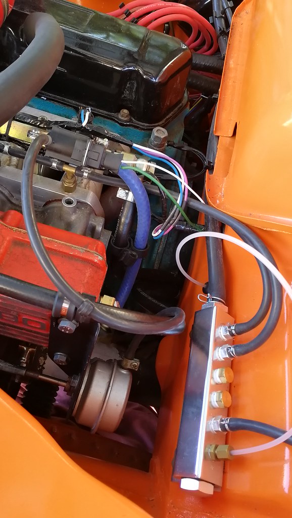
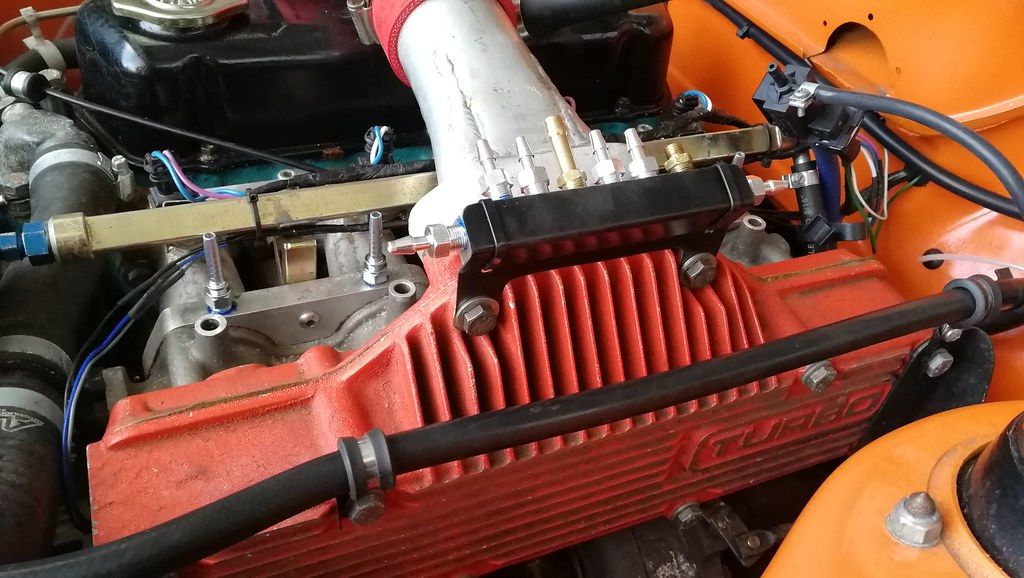
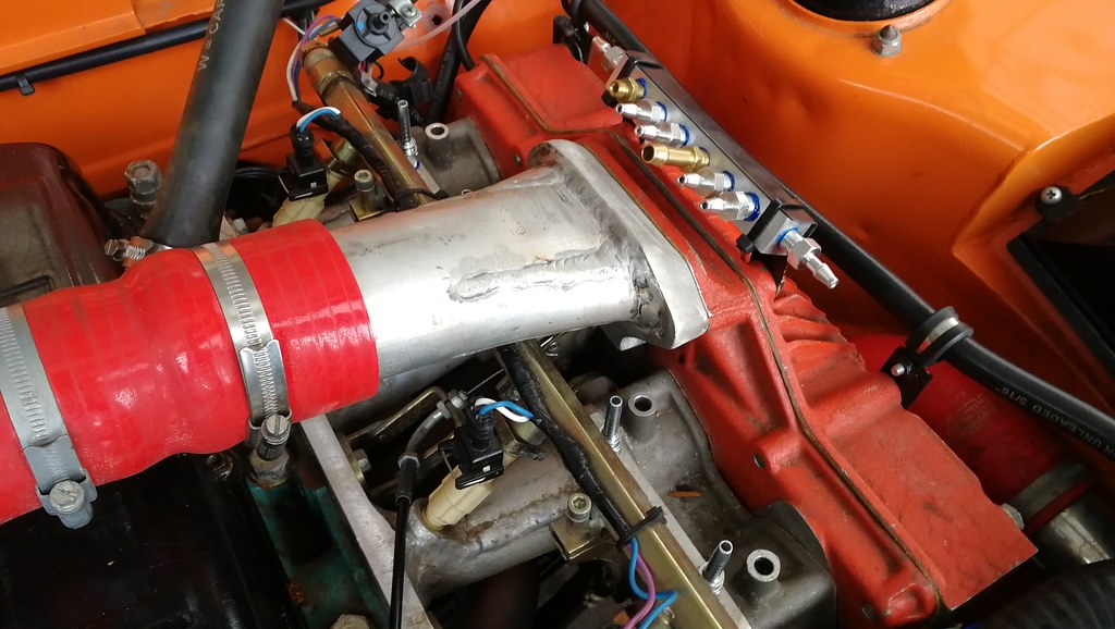
The last few days I have been making a new vacuum/boost manifold. This is the small manifold from which I connect my map sensor, boost gauge, fuel pressure regulator, dump valve and brake servo. With a single throttle body feeding a plenum chamber, this wouldn't be necessary, as all those connections could just be to the plenum chamber. Since I have individual throttle bodies fitted, the vacuum signal from just one runner would be too erratic, and would cause problems for the map sensor, so the solution is to plumb the cylinders together into one small manifold. This damps the signal and also provides a convenient point to plumb all the necessary items. The car is currently fitted with a cheap chinese manifold. This has 1/8" npt fittings. Unfortunately, the quality is low and the fittings bottom out (way) before they seal on the thread. This means I had to use loads of thread tape to get them to seal. The volume of the manifold is also probably larger than it needs to be. I decided to make another one from a piece of aluminium bar, with a smaller internal volume and decent threads which actually seal. I don't have a pillar drill which made it a bit of a challenge, but I managed to drill the main through hole straight enough that it works. I also made this little bracket which will mount the manifold on my plenum chamber, closer to the throttle bodies. Hopefully I can minimise the internal air volume of all the pipes and tidy up the plumbing. Whether it will actually make any noticeable difference is unknown.
I'm going to replace the T-pieces in the inlet manifold (see pic above) with straight fittings as below. This will allow me to connect all 4 runners to the manifold instead of the current arrangement which effectively has 3 connected. I'm currently waiting for some more fittings to turn up in the post.
 IMG_20200229_153627 IMG_20200229_153627 by Chris Witkowski, on Flickr |
| |
|
|
lebowski
Part of things
  Hillman Avenger, Clan Clover
Posts: 488
|
|
|
|
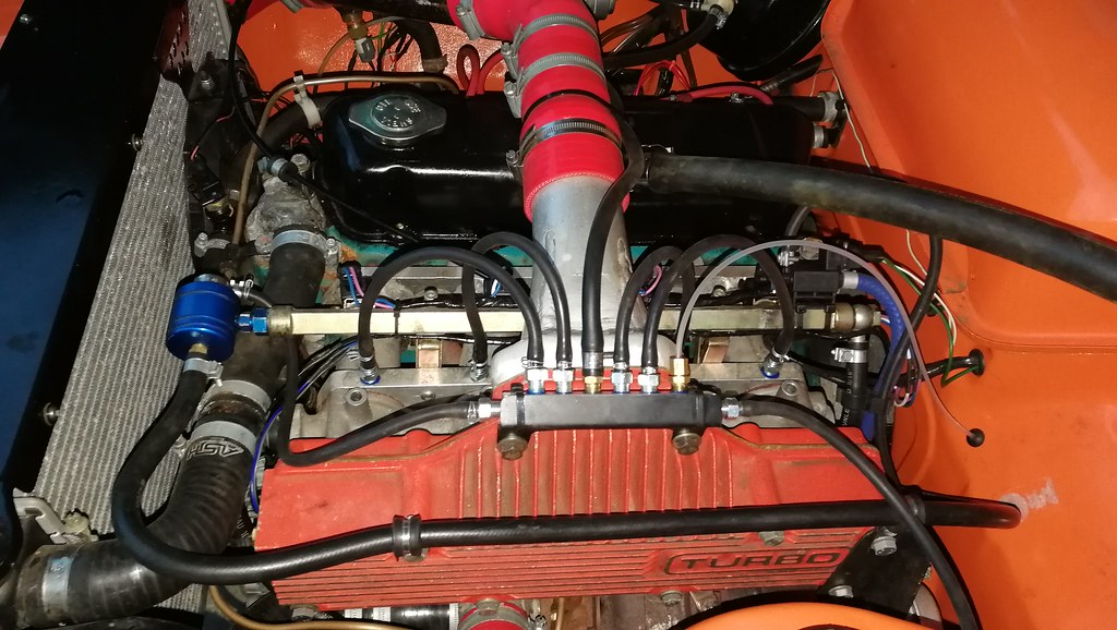
My fittings turned up today so I set about putting everything together. This is how it was initially. With a T-piece in each runner, I effectively had 8 connections from the inlet manifold. Obviously these wouldn't all fit to the vacuum block. I did try joining all the T's together and then just running two pipes to the vacuum block, but the signal was a little weak and unstable. I eventually ended up with the setup below, with some of the connections doubled back to the vacuum block. It was a little clumsy and I wasn't totally happy with it. I replaced the T-pieces with straight fittings and mounted my new vacuum block on the plenum.
All hooked up it looks like this. The larger pipe in the middle goes to the brake servo. I still need to connect one pipe to the map sensor on the ecu, and then reroute that white wire running along the bulkhead (it was hidden behind a pipe before).
|
| |
Last Edit: Mar 4, 2020 20:40:11 GMT by lebowski
|
|
mat88
Yorkshire and The Humber
Posts: 1,542
|
|
|
|
|
Excellent work as ever! I'm quite interested in what you've done for the vaccum manifold.
I'm in a similar dilemma as I need about a million vac lines (map sensor, dump valve, external wastegate etc). But only really have one decent take off from my inlet manifold to use. Would something similar to what you've done work from a single port on my manifold (I was concerned there wouldn't be enough vaccum/boost to give proper amounts of flow through summat like that). Assuming it all works ok fitting something similar to mine would make plumbing a lot easier/neater.
Cheers
|
| |
|
|
lebowski
Part of things
  Hillman Avenger, Clan Clover
Posts: 488
|
|
|
|
|
If you have a single throttle body feeding a plenum then you only need one connection from the plenum to the vacuum block. It should probably be a larger diameter than what I have here I would guess. If your car has an idle control valve connected to the plenum then you may be able to tee into that pipe, ie. Have the ICV feeding the vacuum block, then vacuum block connected to the plenum. I think that's what I would try to do.
|
| |
|
|
|
|
lebowski
Part of things
  Hillman Avenger, Clan Clover
Posts: 488
|
|
Mar 25, 2020 14:14:54 GMT
|
I'm struggling for jobs on the Avenger in this lock down. I have some derusting/painting jobs to do but haven't bought the gear so I can't do them. I have been thinking for a while of trying the original hubcabs on the steel wheels. I've seen lots of cars with banded wheels and their original caps which look great. It has 14" Peugeot 306 wheels, which don't have any clips for the hubcaps but I can sort that later. 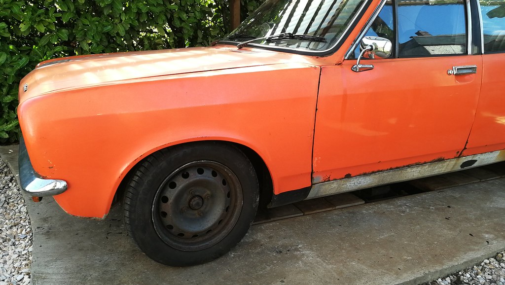 IMG_20200325_131218 IMG_20200325_131218 by Chris Witkowski, on Flickr I used blu tac to temporarily attach the caps. Suffice to say, it looks dreadful! It reminds me of a London taxi which is definately not the look I'm going for.  IMG_20200325_131526 IMG_20200325_131526 by Chris Witkowski, on Flickr  IMG_20200325_131538 IMG_20200325_131538 by Chris Witkowski, on Flickr Ideally I'd like some 5 spoke Revolutions in 14", but they don't come up for sale often. |
| |
|
|
|
|


