Kieran
East of England
Posts: 148
|
|
Feb 12, 2019 21:31:00 GMT
|
Ah, that is fair enough then  My comments weren't meant to dishearten you, just observations. The turbo blanket should help quite nicely though, especially with some exhaust wrap on the neccessary areas  No worries, all comments are welcome! I've tried to research things before starting but I've never done a turbo conversion like this so have no experience at doing it, it's a fun experiment.  |
| |
Last Edit: Feb 13, 2019 18:22:15 GMT by Kieran
|
|
Kieran
East of England
Posts: 148
|
|
Feb 21, 2019 12:42:57 GMT
|
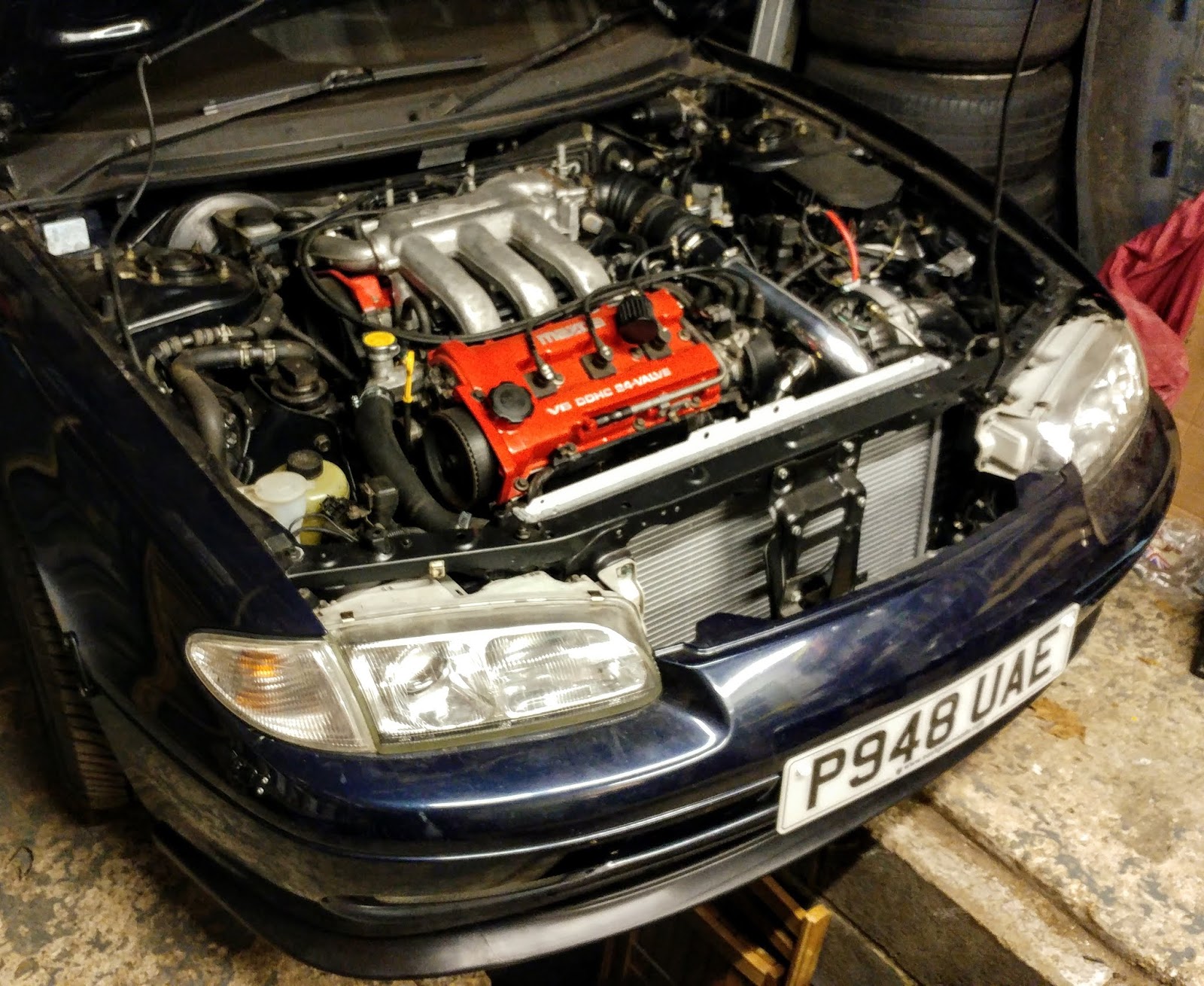
I got a bit done last night. As some may have noticed, in a previous pic' I had the intake coming off the turbo and pointing vertically, obviously I wasn't intending to cut a hole in the bonnet for this! The plan was to cut a hole to have it point down through the body. The panel I needed to cut is next to the frame rail and already had a hole for the now deleted coolant expansion tank filler neck, so this would form part of the new hole. Since the intake pipe is 3" I started off with the 4" hole saw, but this proved awkward so I just roughly chopped out a square shape with the grinder. I did a little trial fit and the positioning seemed satisfactory. Oh, and I need to get a new 3" silicone coupler as this is a cut down one I had.  I cleaned up the apperture edges with a file and fitted some neoprene edge strip that I bought from ebay for this purpose, looks nicer and prevents the intake pipe being scratched.   So the intake piping and air filter now point down though the hole and into the cavity below, this space forms an air box of sorts and will be a source of cold air away from the engine bay. The pic shows this area with the bumper removed. I'm not sure whether I should open this space by removing the section of wheel arch liner that forms the bottom side, or whether cutting this away with create excessive air turbulence around the cone filter resulting in less air flow...  Anyhow, quite satisfied with the work. Also, the longer 10AN oil drain line for the turbo has arrived, still awaiting the new fitting required so then I can get those fitted up.  |
| |
|
|
Kieran
East of England
Posts: 148
|
|
Aug 14, 2019 15:00:10 GMT
|
|
I see that it's been quite a while since I put an update here. Things have progressed slower than I would have liked, but I did managed to do a first start at the weekend, so the motor does run with the turbo now...
|
| |
Last Edit: Aug 14, 2019 15:00:46 GMT by Kieran
|
|
ToolsnTrack
Posted a lot
   Homebrew Raconteur
Posts: 4,137
Club RR Member Number: 134
|
|
|
|
|
A first start is an important milestone. When is the first test roll under it's own power? Who's doing the mapping?
|
| |
|
|
Kieran
East of England
Posts: 148
|
|
|
|
Yes a milestone indeed, I'm really pleased to get to this point. I've still some work to do to get to the stage where it's properly driveable though. The main job to do is replacement the fuel pump as the standard one won't flow enough fuel for boost. It's still in the tank so I need to swap this for the higher flow part that I have already bought. I also still need to wire up the AFR, boost and oil temp gauges.  My first stage setup to get things up and running is to run low boost (I've a 3.63psi wastegate spring installed) using the standard ECU with a 12:1 FMU, so no mapping required for this. I've somewhat larger injectors with the fuel pressure dialed down a bit with an adjustable fuel pressure regulator. If anyone is unsure what an FMU is, it's a fuel management unit, basically a rising rate fuel pressure regulator that will cause a rise in fuel pressure under boost, so the injectors will flow more fuel.  My stage 2 setup once I have everything mechanically sorted will be to swap the standard VAF (vane airflow sensor) for a MAF (mass airflow sensor) and use a Pilot Engineering piggyback ECU I have already bought to convert the sensor signal to the ECU and control the mapping. The piggyback ECU has a bluetooth transceiver to communicate with an android app that I have installed on my phone, so I can adjust the map on the road. So the answer to the question is, I will be doing the mapping.  I have designed a little housing for the piggyback ECU PCB in CAD, still need to 3D print it.  I have already trial fitted the MAF intake setup. This pic' shows me holding the FMU while I was fitting it.  This is how the engine bay currently looks with the VAF fitted in the intake. To the right of it is the FMU mounted on the strut tower.  A stage 3 setup will be to build a megasquirt/microsquirt or Speeduino standalone ECU to fully control fuelling and ignition, I see this a quite a big project in it's own right so it will take me some time to get this implimented. |
| |
Last Edit: Aug 15, 2019 8:50:57 GMT by Kieran
|
|


