Darkspeed
Club Retro Rides Member
Posts: 4,878
Club RR Member Number: 39
|
The Flowbench thread.Darkspeed
@darkspeed
Club Retro Rides Member 39
|
May 11, 2018 18:42:28 GMT
|
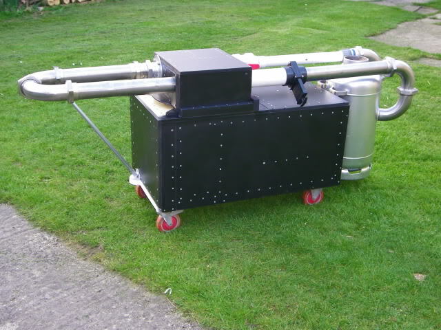
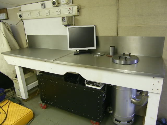
At least I can edit the title at any point in the future when I manage think of something witty and interesting to grab attention. I covered a bit about this in the Stratos thread and I will drag some of the posts I made there over to this thread but as its my intention to keep the bench running and do more regular work on it I figured a dedicated thread is really the way to go - There are also a couple of other peeps on this board from the PTS board who may also feel inclined (manometer pun) to contribute to this thread. Some years ago now I built myself a Flowbench from the PTS flowbench plans. www.flowbenchtech.com one of those things that fascinated me and probably indicates too much time reading books and articles by David Vizard. Looks like the photo's in the Strat' thread are PB hosted ones so will load new ones. I will aslo do a bit of cutting and pasting from the old thread to save repeating repeating myself myself. Reading below I already appear to be!
A while back I decided to build myself a flowbench, I had enjoyed modifying cylinder heads with a bit of simple porting following the guides on Pinto tuning by Mr Vizard and tweaking Rover V8 heads from information given to me by people who had vast experience in making good power from them, but being an engineer I was unhappy about not being able to measure the improvements being made even though I had no reason to doubt the information written or the advice being given. There are generally two choices when it comes to measurement of modifications to an engine that have been carried out to improve power. Choice one is building the engine up complete and putting it on an engine or a chassis dyno and measuring the power produced - preferable against an original datum so that direct comparisons can be made. The other measurement is with a flowbench. And engine being an air pump its ability to pump air has a direct relation to its ability to make power and therefore the cylinder heads ability to flow air is also directly related to that ability to produce power. Buying a professional flowbench for the odd bit of home porting is prohibitively expensive so the amateur head fettler has a couple of options - do without or try and build one. Lucky for me I started to get interested in flowbenches just when a chap in the USA was offering plans for sale on a bench design he had designed. www.flowbenchtech.com/Armed with a set of plans delivered in the good old method of paper in the post from the USofA I got stuck in with the build. Somewhere on an old PC or laptop there is a file with all the flat bits of MDF on it so you are sped along to the ones I can find with part assembly already complete. 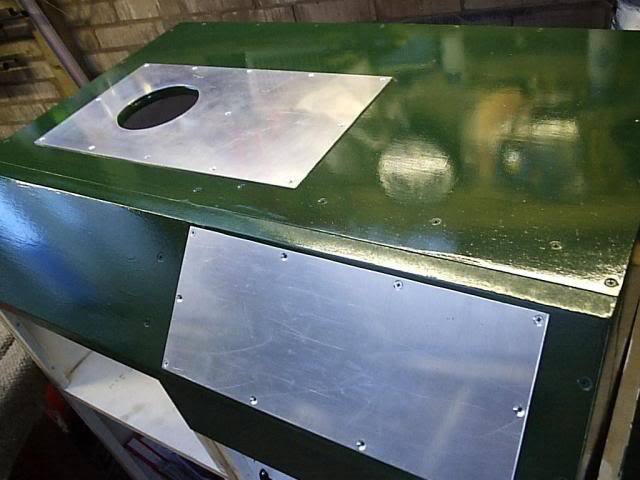 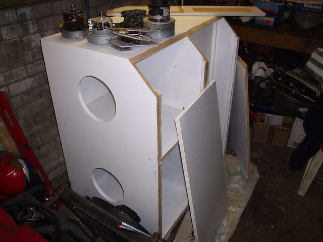 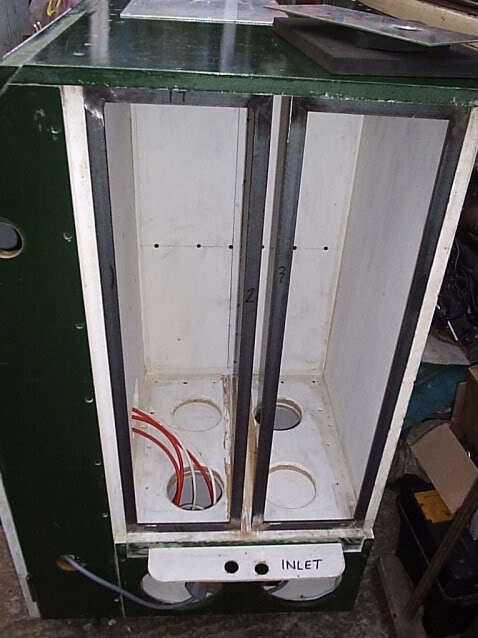 The PTS bench is an orifice bench and a ratiometric device which basically means that it measures flow across a calibrated sharp edge orifice and that as the air through the head is at the same temperature as the air through the orifice it is self compensating so all you need to do is allow for the atomospheric temperature in your calculations. Other types of bench need a bit more effort in the calculations. I am being brief as everything you would need to know is out there to find. I liked this bench design as it also has the facility to flow the exhaust ports in the direction of flow of the gas in the engine by reversing the bench flow. Typically you would just take the exhaust flow in the same manner as the inlet port but with this you can check the measurements you have and see if any anomalies crop up. I built the bench to the full specifications of 8 vacuum motors - each is about 1300 watts so flat out its drawing a fair bit of power - single phase 10.4kW or 13HP or about 42 Amps (again a simplistic calc) so a bit of a draw on the garage socket  At 8 motors the bench can pull over 40" inches of water vacuum at a flow rate of 450CFM - you will have to take my word for it that its moving quite a lot of air and that's quite a pressure drop. The Rover heads I was playing with have a maximum flow potential of at the very best 200CFM at the standard 28" pressure differential so with that I blocked off 4 motors before I had to find a way of putting the smoke back in the house ring main. Getting it back into Heated rear window circuits in old Fords is hard enough. Wonky picture showing the orifice plate in the settling chamber that sits under the port any fixture sit on. The studs hold a baffle and the chamber is there to slow the air once its been rattled past a valve and give it time to sort itself out so it can pass nice and orderly through the orifice - chambers and baffles are mirrored because of the ability to reverse the flow. 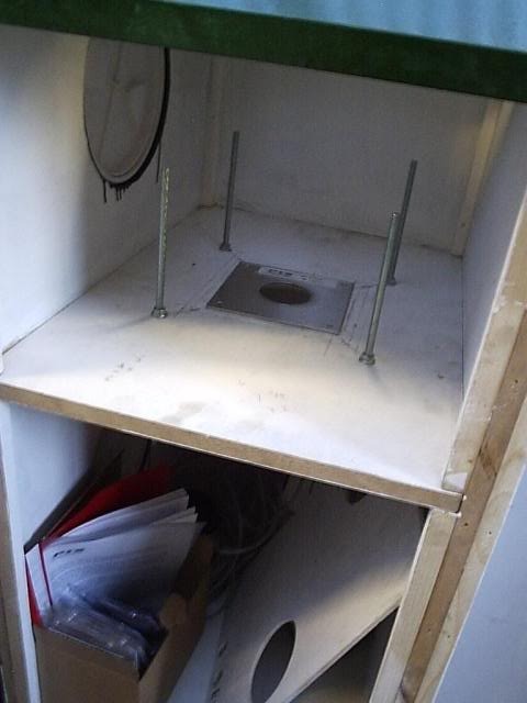 |
| |
Last Edit: May 13, 2018 15:35:31 GMT by Darkspeed
|
|
|
|
Darkspeed
Club Retro Rides Member
Posts: 4,878
Club RR Member Number: 39
|
The Flowbench thread.Darkspeed
@darkspeed
Club Retro Rides Member 39
|
May 11, 2018 18:46:26 GMT
|
This is the main motor board - I manged to find 4 quite powerful 2 stage motors which are the ones that I use in the main now that the other fours have been blanked off. They can flow a fair bit on their own and will easily take a well ported Rover V8 to the limit of the 36" sensor. 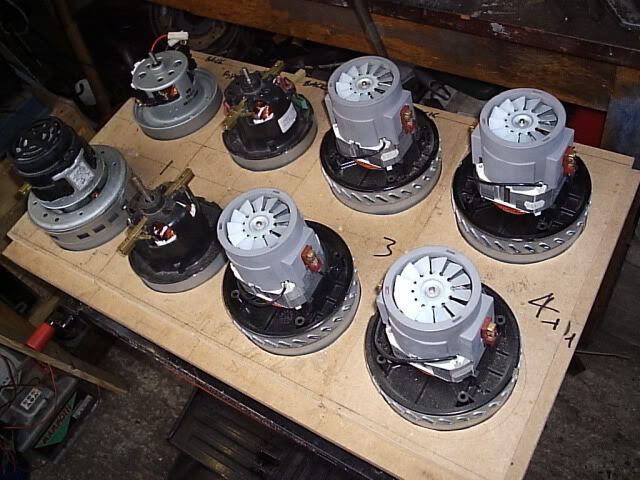 en.wikipedia.org/wiki/Orifice_plate The principle is very simple - the link above will explain it better than I can and also shows - if really keen - the associated calculations to determine the rate of flow of what fluid is passing through the orifice. The orifice plate between the settling chambers has a carefully machined knife edge and for it's diameter it has a given Coefficient of Discharge. When thrown in a calculation with the physical properties of the fluid being measured a rate of flow is spat out. So very simply Pressure A on side A - compared with Pressure B on side B = Flow rate C . So all of that effort to build the box and wire all the motors and some other stuff is just to measure the air flow across that plate. - Accurately How that translates to what is going on with air flow through whatever you bolt on to the top of the bench will be along in a bit. This is what it looks like when you decide to check on David Vizard and the flow through an old Pinto 32/36 DGAV that has had the chokes bored out to 30mm and lots of little tricks like knife edged butterfly plates, slimmed down and knife edged auxiliary venturies and the like  |
| |
|
|
Darkspeed
Club Retro Rides Member
Posts: 4,878
Club RR Member Number: 39
|
The Flowbench thread.Darkspeed
@darkspeed
Club Retro Rides Member 39
|
May 11, 2018 18:55:54 GMT
|
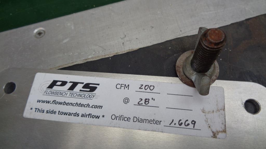
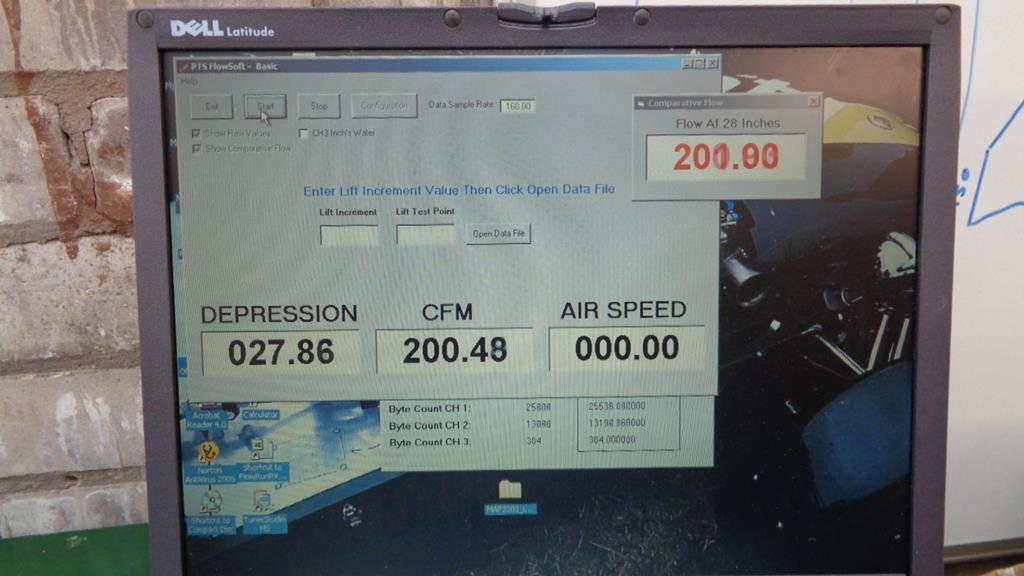
So, electricians please look away now - functionality first - and this is the heart of the beast 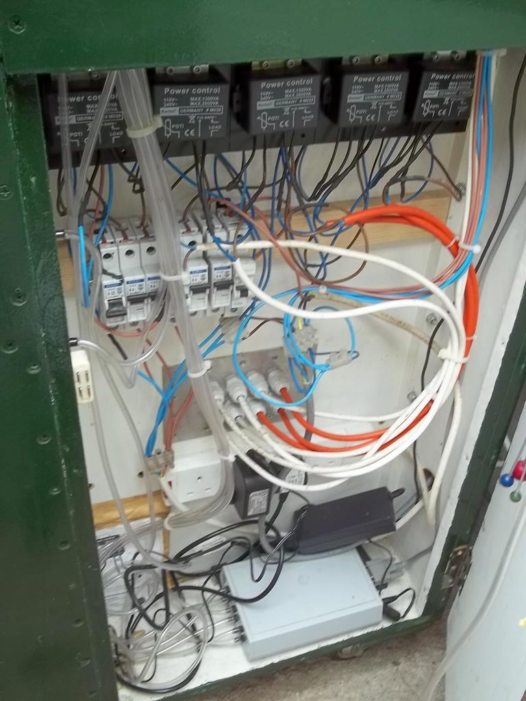 Up top we have 5 variable speed motor controllers each is rated at 2400 watts if i remember correctly, and each is then mounted on a large heatsink even though they seldom get warm at the test pressures and flows that I run the bench at. 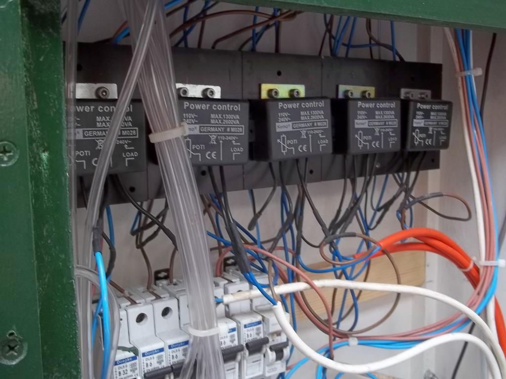 The little box in the bottom of the cab under the laptop power-supply is the clever part of the kit, the digital manometer. On a lot of older benches you will find vertical and inclined water column manometers. The trouble is that when you start pulling vacuums of near 40" that's quite a tall gauge and when you are trying to get good resolution on flow improvements the inclines also need to be carefully designed. It's also very easy to get sloppy and suck all the fluid out of the gauges and into the bench!! 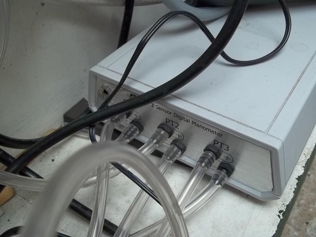 All these little air tubes connect to a couple of ported valves and the pressure tappings that pick up the pressures in the two chambers either side of the orifice. 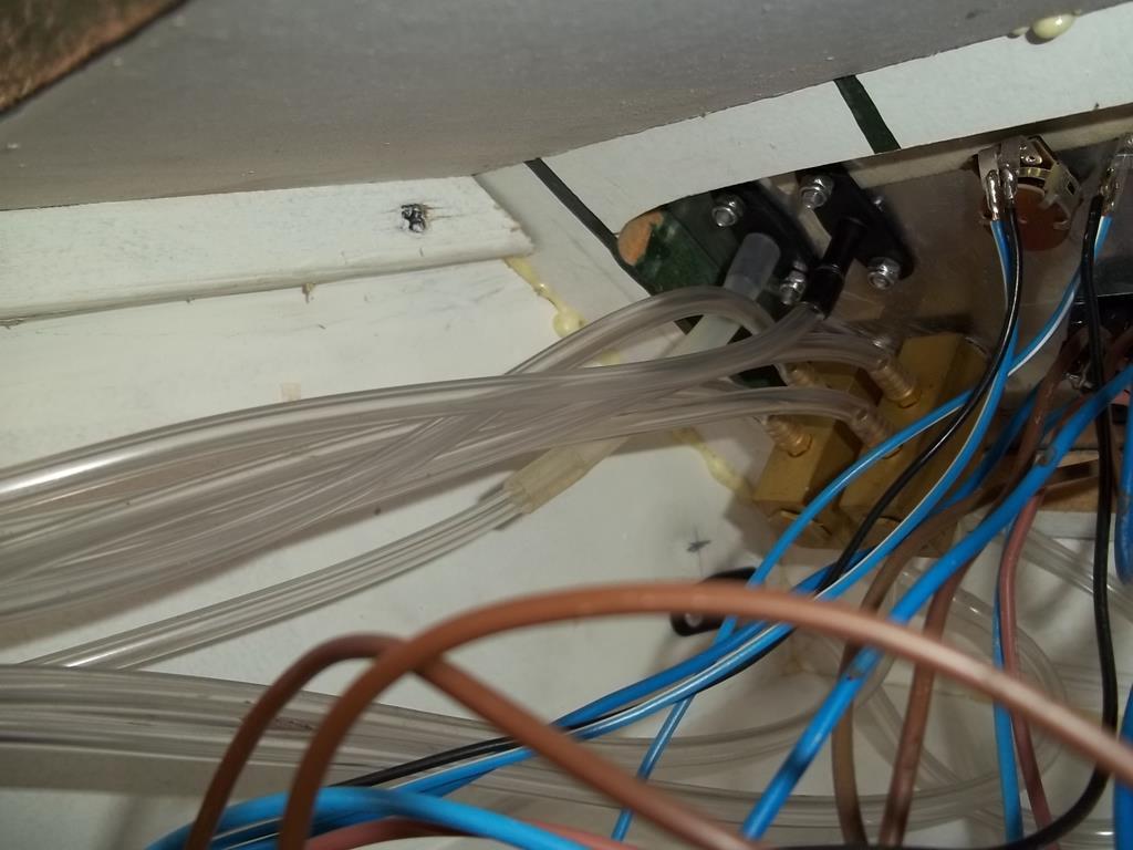 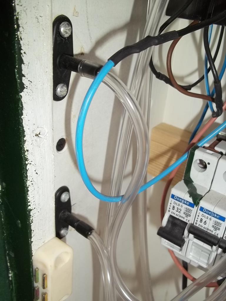 This is then all connected up to the control panel. 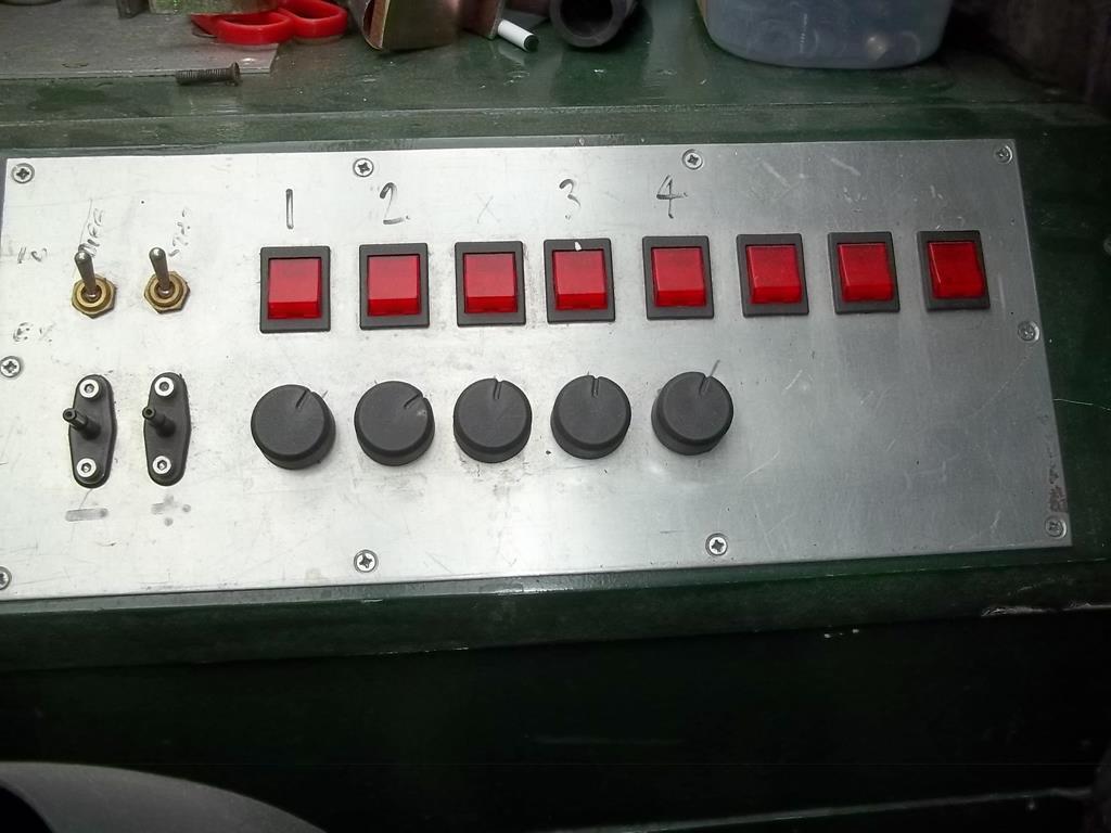 I really should invest in a label maker and stick some better labels on it. I keep promising myself to sand it all back and paint it correctly and make it look respectable - I will eventually Taking a peak down an adapter you can see the baffle over the orifice place - I made them clear so that I could fit lights in the chambers to reflect up the ports. The pro's will make the adapters from acrylic so that they can view what's happening. 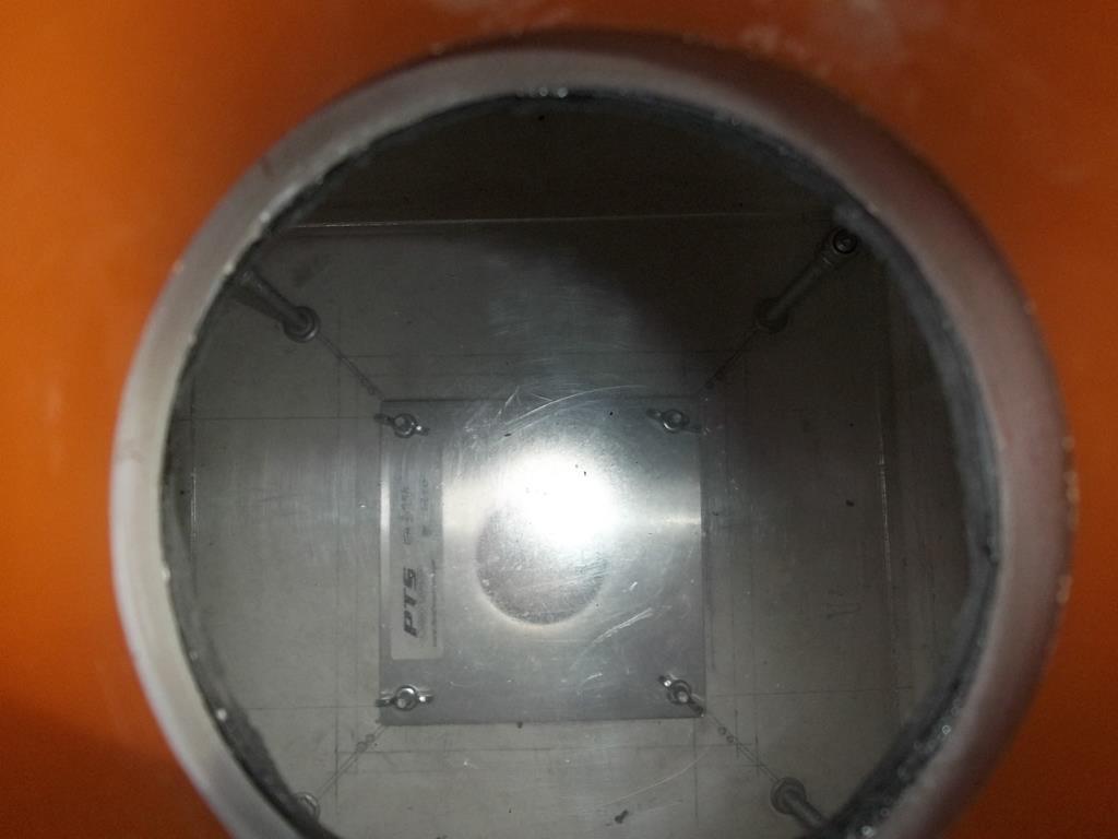 If you have gone through all the trouble of building a measuring device you really need to be able to test it's accuracy - no point having a ruler if it's calibrated differently to everyone else's ruler - These differences in units eventually end in issues and disappointment. I especially love the Mars Orbiter mission where an error was made with Metric and Imperial. What you need for repeatability is the ability to calibrate the bench against a datum and PTS produced a set of calibration plates derived from what were known as pass around plates. These were a set of plates that builders used to test the accuracy of benches and these original plates were then standardised into calibration plates. 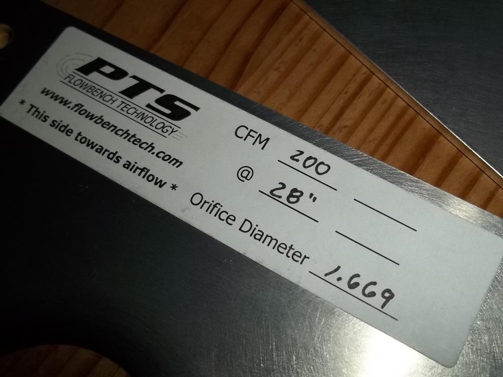 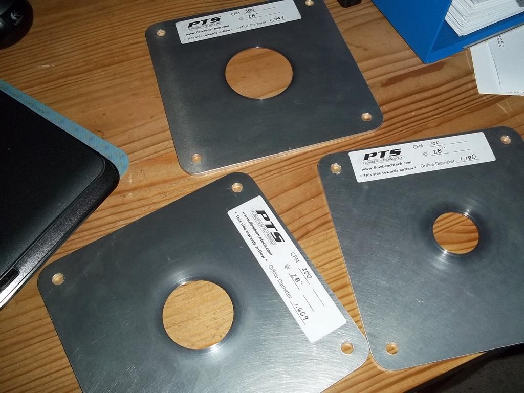 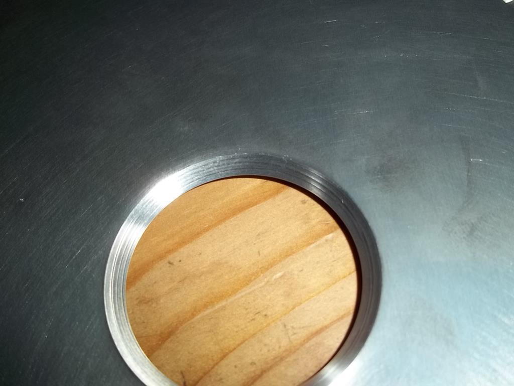 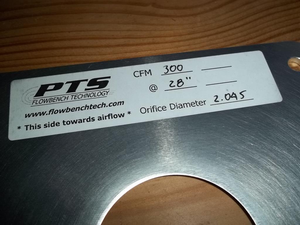 These plates have since been tested on other manufacturers plates to confirm accuracy across not only PTS benches but many other makes. Originally I ran the bench and calibrated it from a standard set of calibration figures and did not have it calibrated - when using the bench as a comparator and not an absolute measure calibration it is not 100% important but it's always nice to know that the figures you are reading actually have a place in the real world. When I eventually purchased a set of plates the bench was less than 2% out. |
| |
Last Edit: May 11, 2018 19:34:38 GMT by Darkspeed
|
|
Darkspeed
Club Retro Rides Member
Posts: 4,878
Club RR Member Number: 39
|
The Flowbench thread.Darkspeed
@darkspeed
Club Retro Rides Member 39
|
May 11, 2018 19:59:26 GMT
|
We will continue to rip the posts out of the old thread for a bit - cannot believe this was two years ago.. I was over at an old pals place - near two years ago - giving him a hand with a few things as he has torn something or other in a bicep. Whilst there I collected an old 40DFA to replace the heavily modified 32/36 on the G31, which to my annoyance has recently decided to start to decompose. More annoyingly is the fact I had an equally modified 38DGAS which I am now kicking myself for selling. 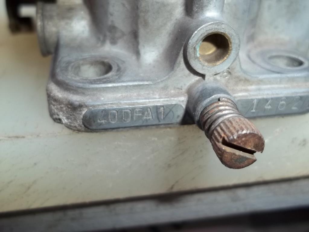 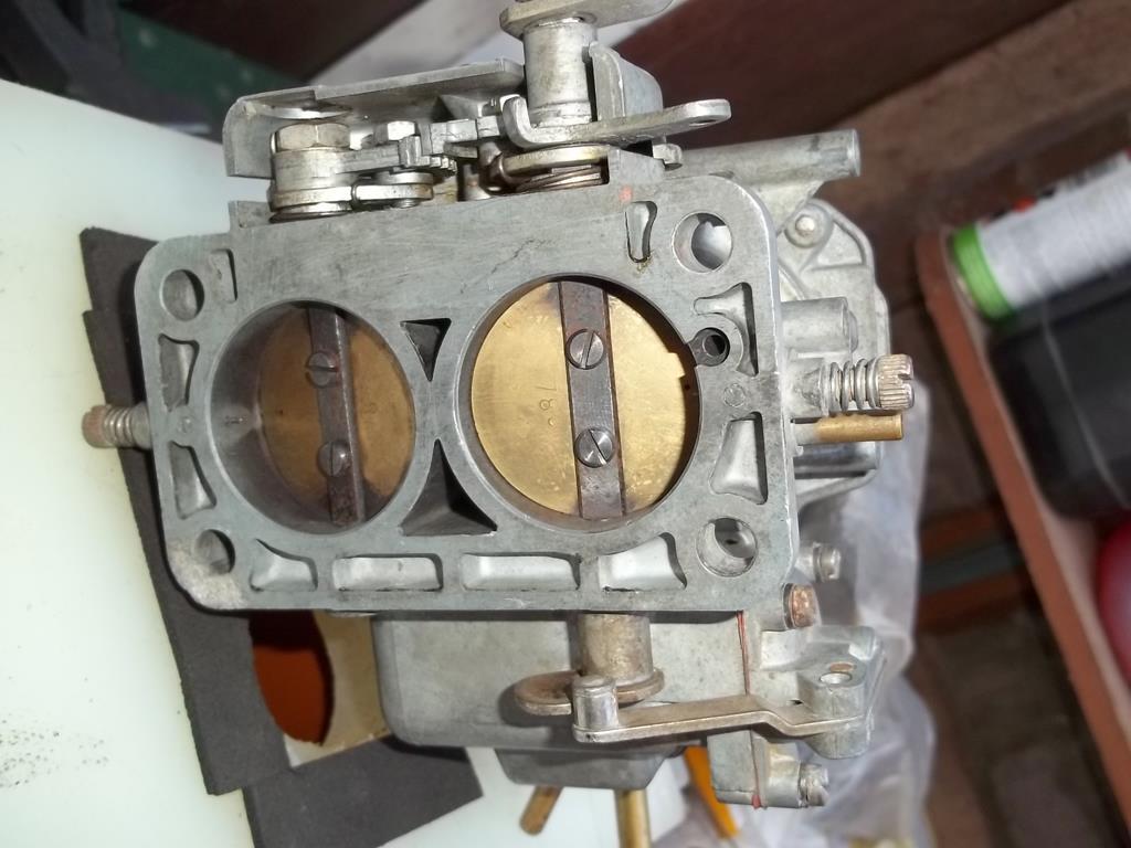 When I left, the back of the car had accumulated this little lot. 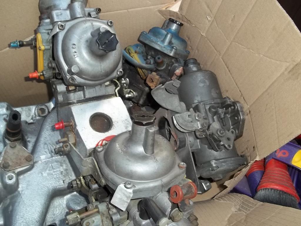 And a ported Vauxhall 1400 round port inlet manifold, throttle body and decompression plate that he had done for a customer for a turbo installation a good while ago for me to list on ebay for him! The Rover V8 manifold is only there to give up one of the Strombergs as a donor to match with the SU. I have been given them to settle a pub argument/discussion about what carb has the better flow potential, this "discussion" has been rumbling on for quite a while so I offered to stick both on the bench and settle it. The carbs will then go back to my mate Roy who will do a few little porting tricks on them and they will be back on the bench to see what the improvements are. For me I want to see the flow difference between my modified 32/36 and a standard 40DFA - a 32mm/36mm against a 40mm/40mm - no contest? I think it will be pretty close as the 32/36 has 30mm venturi bored into it and the 40DFA has the standard 28mm dia so how close will they be? |
| |
|
|
Darkspeed
Club Retro Rides Member
Posts: 4,878
Club RR Member Number: 39
|
The Flowbench thread.Darkspeed
@darkspeed
Club Retro Rides Member 39
|
May 11, 2018 20:06:48 GMT
|
Well it took a bit of time to get a suitable adapter made up but I got them on the bench - this was a very quick test as all it needs is a full flow comparison. 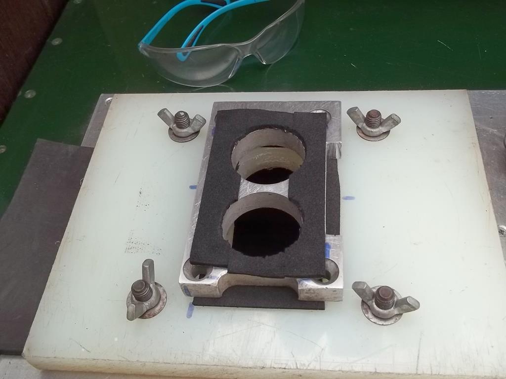 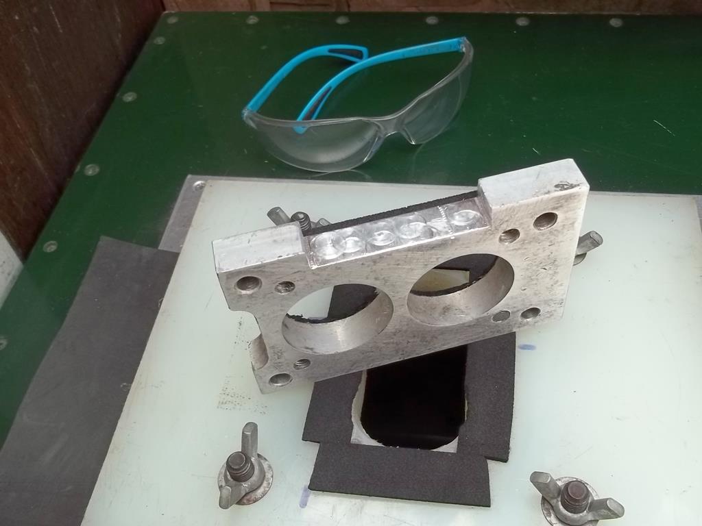 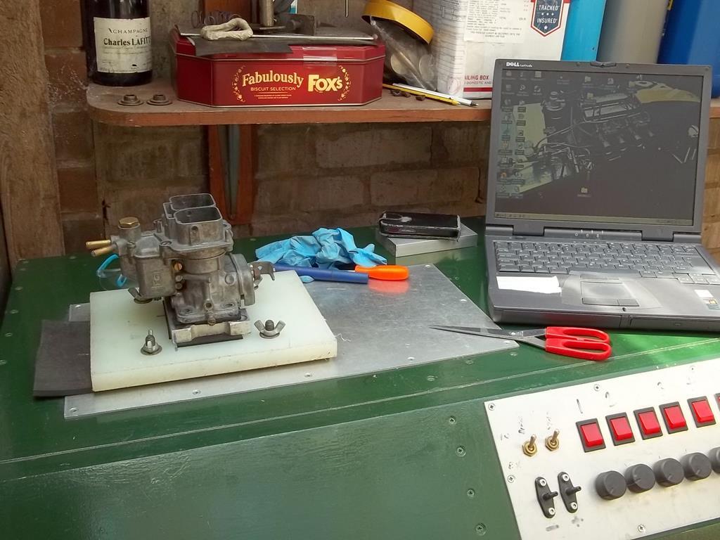 Modified 32/36 DGAV - 335 CFM @28" Standard 40 DFA - 400 CFM @28" 18% more flow out of the 40 DFA - to be honest I thought it would be a little closer than that so I thought maybe the 32mm choke really hurts the flow so I then did a quick test of the 36mm choke on its own. 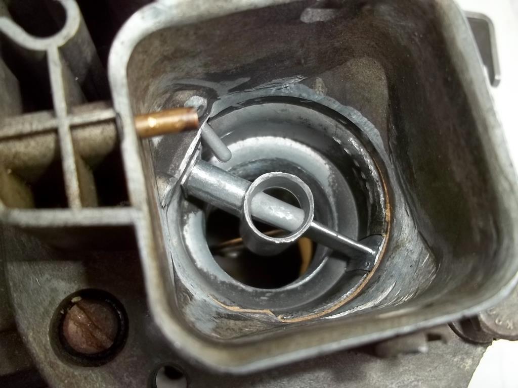 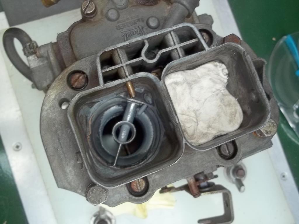 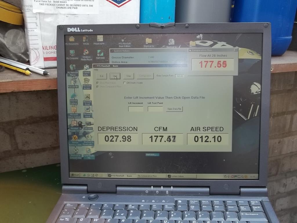 I did manage to get 179CFM out of the 36mm choke the 177 was due to the butterfly moving a little whilst I was taking the photo. On the 32mm choke only I measured 151 so 330 together which is close enough as there may be something going on with the airflow that allows a little more when both are open at the same time. One thing I can tell you is that it was incredibly noisy to test. |
| |
|
|
Darkspeed
Club Retro Rides Member
Posts: 4,878
Club RR Member Number: 39
|
The Flowbench thread.Darkspeed
@darkspeed
Club Retro Rides Member 39
|
May 11, 2018 20:11:44 GMT
|
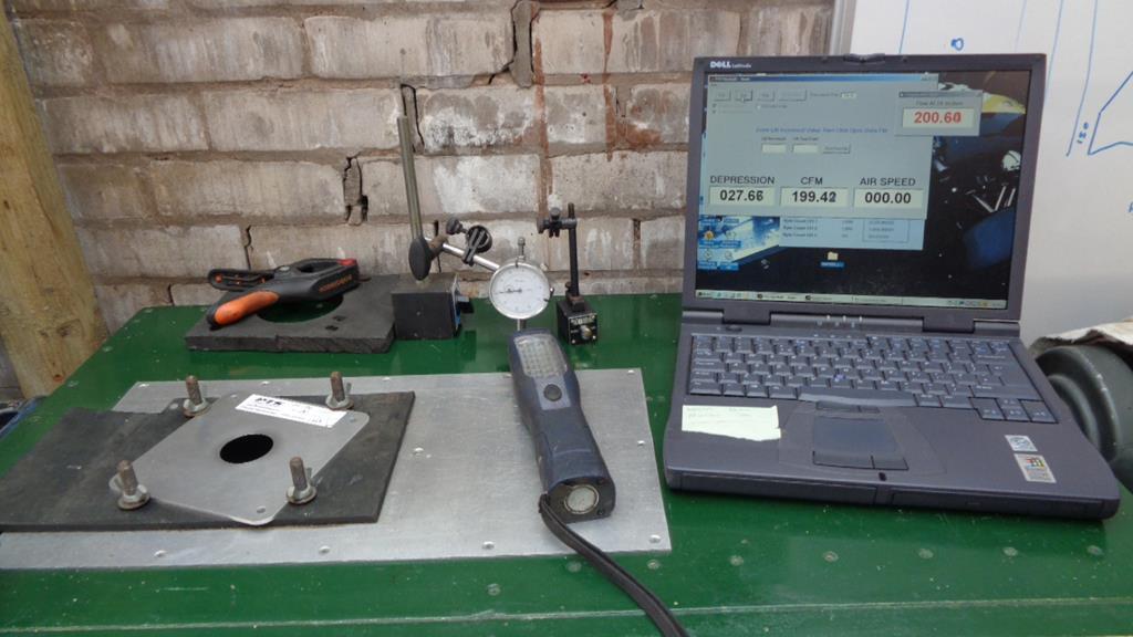
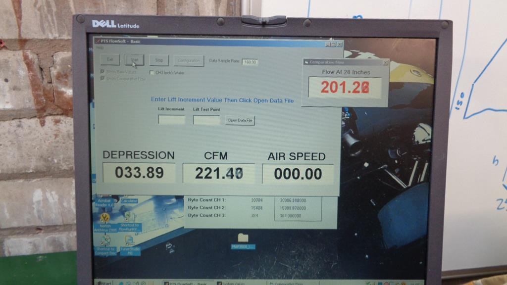
Useless information time - outside of this forum at least- but with a little relevance to this thread. Ever wondered what a 390, 450, 600 etc that Holley use for sizing 4 barrels actually means ? Well the figure that Holley put on the box is the air flow in CFM at a pressure differential of 1.5" Hg - Hg is Mercury and as it's a pretty heavy doohickey it takes a bit of suck to get it moving 1.5" up a tube - its the same as about of pressure required to move water 20.4" up a tube. Note - 2 Barrel Holleys are tested at 3"Hg so do not compare the two a 390 two barrel is not the same as a 390 4 barrel. converting Hg to Wg and flow at 20.4" to flow at 28" is actually quite straight forward. My flowbench operating program has a conversion built it - the picture below of me testing a modified 38DGAS shows three sets of figures. 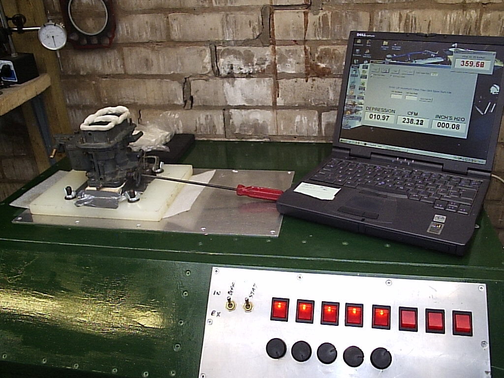 Depression - This is the actual measured pressure that the carb is seeing from the bench. Flow - This is the measured flowrate of air through the carb at that depression Ignore the lower right hand figure that channel is not being used. Up in the corner is a comparative flow figure that I have set to give an airflow reading that would be equivalent to 28" - This allows you to do a lot of testing at lower(and quieter) flows and you just need to whip it up to 28" actual to do a double check. At lots of benches just do not have the capacity to test over 10"wg. Back to the subject A 390 Holley flows 390 CFM at 20.4" wg which at 28" is - 457CFM If we want to compare our 400CFM 40 DFA Weber in Holley 4 barrel numbers that is 341CFM A 390 two barrel Holley - flows 323CFM at 28" - about the same as a stock 32/36 DGAV Hopefully this has also highlighted that without that crucial "wg figure - flow figures for anything are absolutely meaningless. |
| |
|
|
Darkspeed
Club Retro Rides Member
Posts: 4,878
Club RR Member Number: 39
|
The Flowbench thread.Darkspeed
@darkspeed
Club Retro Rides Member 39
|
May 11, 2018 20:24:17 GMT
|
Did the Triumph throttle body today Test result without a nice radius on the intake 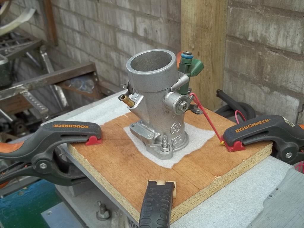 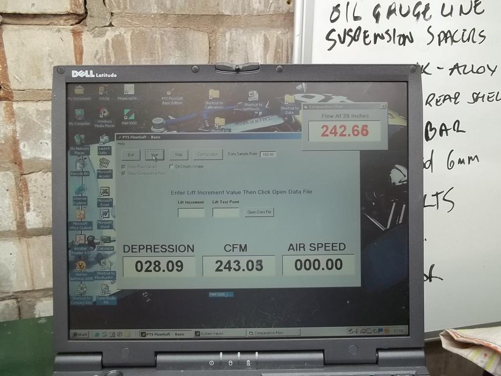 And with a nice radius on the intake. 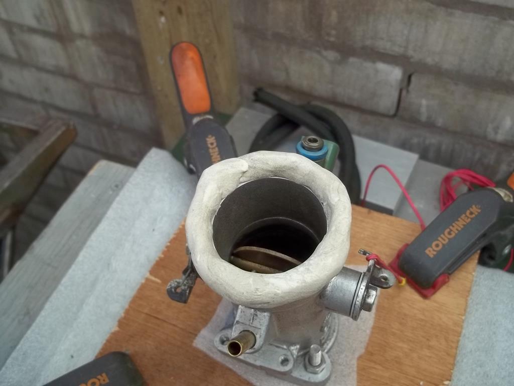 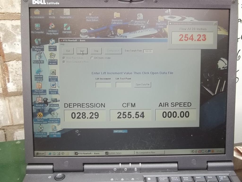 I nice bellmouth inlet on that is well worth the effort looking at those results Flow at 250CFM @ 28" - The manifold will offer no resistance to flow and should even enhance it a little - I will do some further tests on this throttle body as I think I can grab a little more flow from them. It will be interesting to get a head on the bench and see what capacity it has. |
| |
Last Edit: May 12, 2018 6:54:11 GMT by Darkspeed
|
|
Darkspeed
Club Retro Rides Member
Posts: 4,878
Club RR Member Number: 39
|
The Flowbench thread.Darkspeed
@darkspeed
Club Retro Rides Member 39
|
May 11, 2018 20:46:19 GMT
|
I put a couple of carbs on the rig to answer a question that came up with the lads down the pub on what flows better - an 1 3/4 SU or a 1.75 Stromberg SU made 262 CFM @ 28" and the Stromberg 247 CFM @ 28" I tested both with a generous radius on the intake and with the SU it made no difference and on the Stromberg it increased flow to 250 CFM - The SU has a slight taper into the carb the Stromberg does not. Before I did the tests I figured that the Stromberg would flow less as its smaller internally than the SU My mate that does lots of head porting is going to give the SU a go over to see what improvement in flow there is. This evening I may make up another simple adapter and put one of the Triumph throttle bodies I am using on the Honda engine on the bench and see what the flow capacity is. 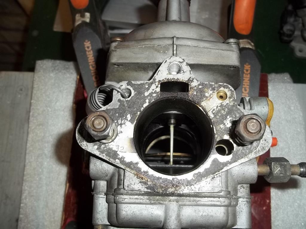 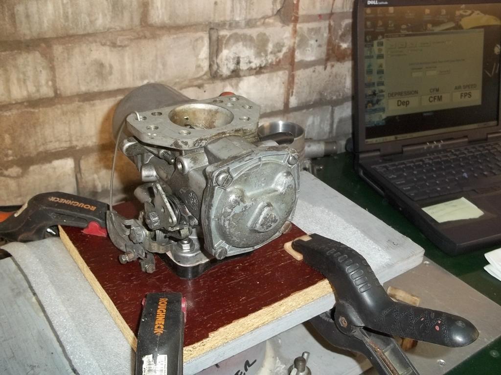 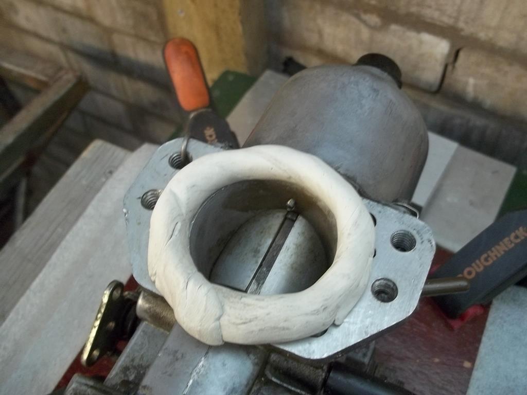 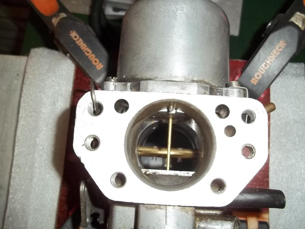 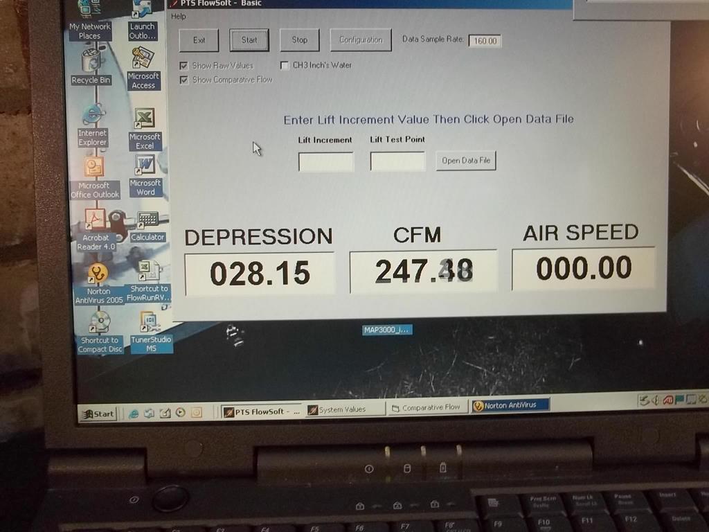 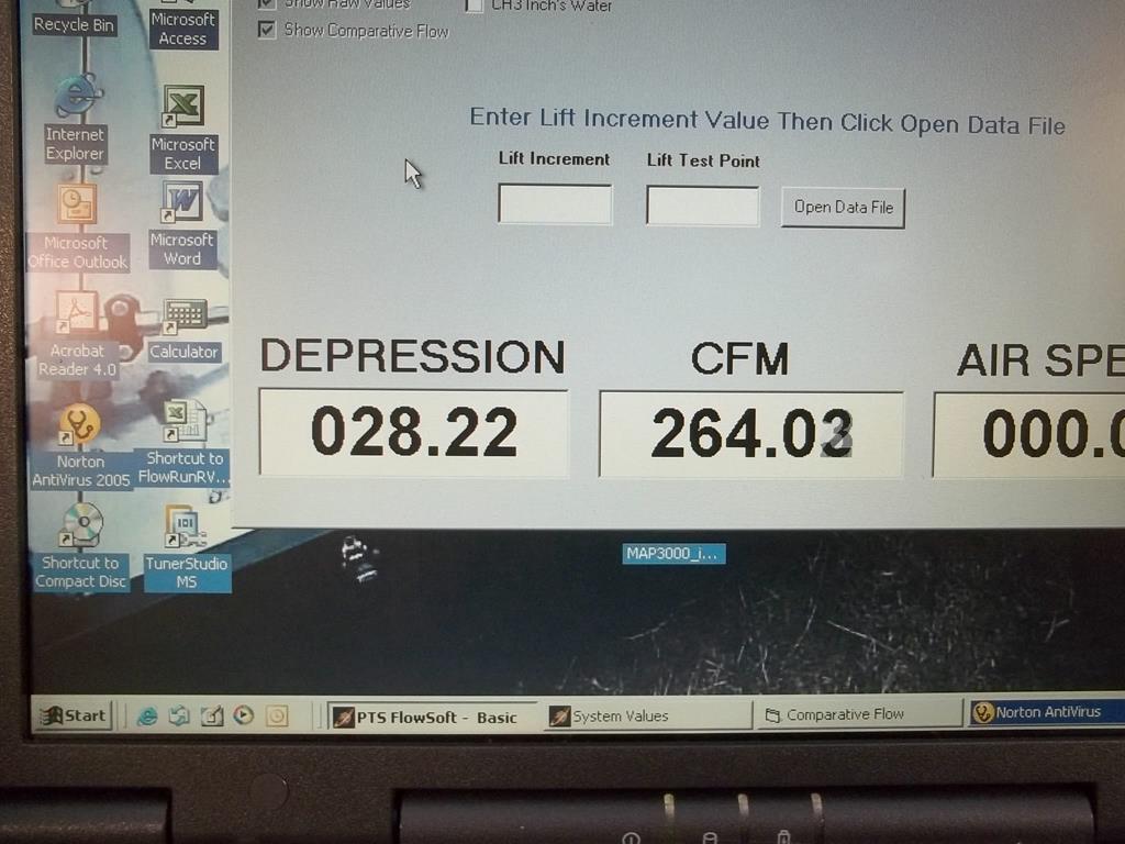 |
| |
|
|
Darkspeed
Club Retro Rides Member
Posts: 4,878
Club RR Member Number: 39
|
The Flowbench thread.Darkspeed
@darkspeed
Club Retro Rides Member 39
|
May 11, 2018 20:58:47 GMT
|
And if we look at the flows achieved for the Triumph throttle body - and the SU/CD we can see just how close they are - let's see what a 40 IDF flows 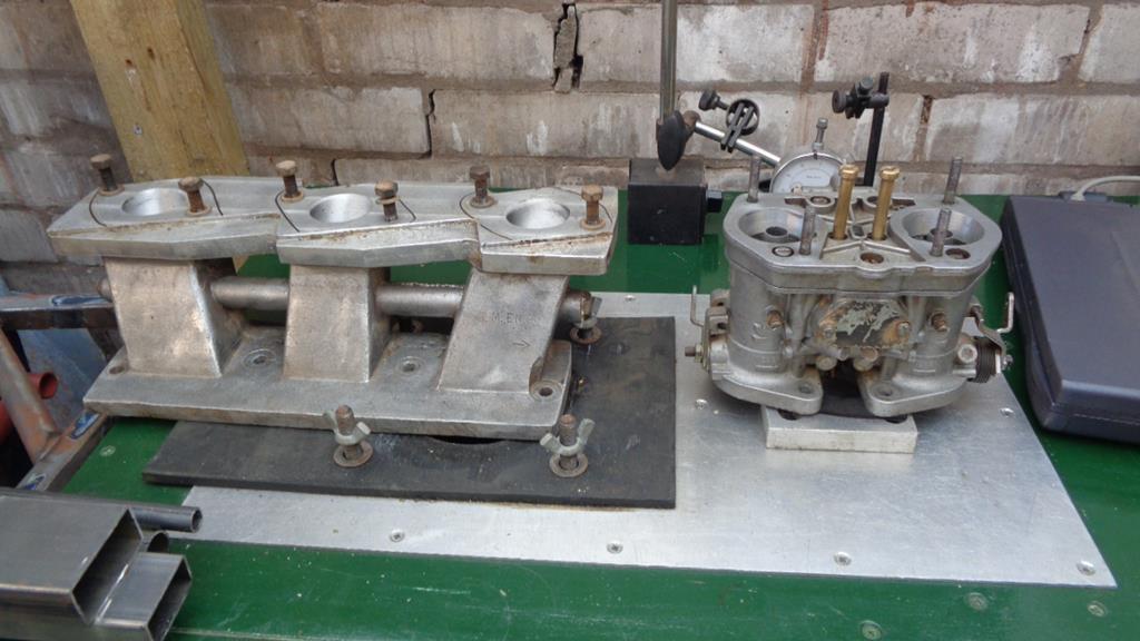 With 32mm and 34mm and a 36mm chokes - and an empty body - When they arrive we can see how the 44 IDFs with the 36mm chokes perform and as we have some 45 IDF throttle bodies we can test those as well  - I suspect that the IDF manifold will be a restiction at some point. 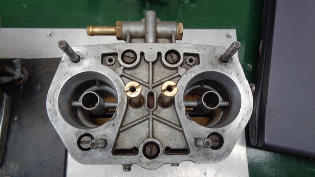 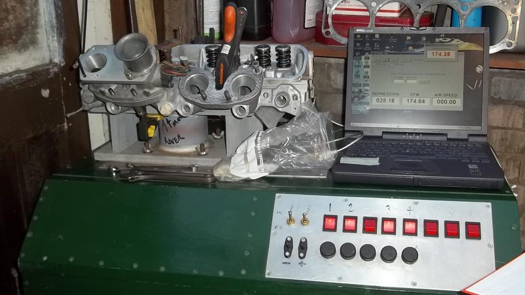 |
| |
|
|
|
|
|
|
Darkspeed
Club Retro Rides Member
Posts: 4,878
Club RR Member Number: 39
|
The Flowbench thread.Darkspeed
@darkspeed
Club Retro Rides Member 39
|
|
|
I think I might have a couple more, maybe ... Be interesting to see what the difference is in flow rate between a modded DGV and a standard DGS too. Picking through the posts above there was not much to choose between a modified 32/36 DGV and a Modified 38 DGS so I suspect a modified DGAV will have a smidge more flow than a stock DGAS Modified 32/36 DGAV - 335 CFM @28" Standard 40 DFA - 400 CFM @28" Modified 38 DGAS - 360 CFM @28" What I did find with the DGS over the DGV was far better economy due to having that smaller choke to run on but the DGS felt far more "sporty" with it opening both chokes quickly. Banging both to the floorboards there was not much difference which is why I sold the DGAS and kept the DGAV. The other stock carb in the box is a 34 DGAS from the 2.5 Ford V6. Interesting that the 38 DGAS was a popular conversion onto the Rover V8 - 2 X 3/4 SU 520 CFM @28" 1 x 38 DGAS around 330 CFM @28" 1 x 390 Holly 4 barrel 457 CFM @28" I suspect that 8 x 45mm IDF TB's are 2400 CFM @28" But for engine power there are big differences between manifolds that allow all cylinders to draw from the same carb and those that split the flows and individual runner per choke types. |
| |
|
|
|
|
|
|
|
|
I'm not a carbie man, so the numbers don't mean much to me, but the ability to measure head porting or manifold porting would be interesting.
Not that I'm an engineer or have the slightest clue about air flow/fluid dynamics, but I always thought that standard, mass produced manifolds could be made so much better by getting rid of casting burrs, superfluous lips etc (I saw a Honda Civic TypeR manifold yesterday that looked like it had nearly 4mm of lip on the exhaust manifold ports that could possibly have been ground off).
|
| |
|
|
|
|
|
May 13, 2018 21:12:44 GMT
|
Great work - I'm looking forward to seeing how 40IDFs on IR RV8 manifolds, flow if you are going to test those soon. I also ran a pair of 38DGAS carbs on a Rover manifold..... 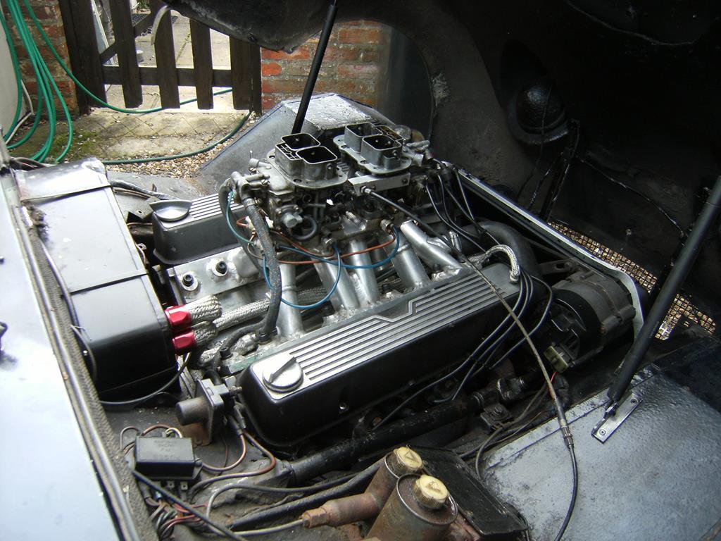 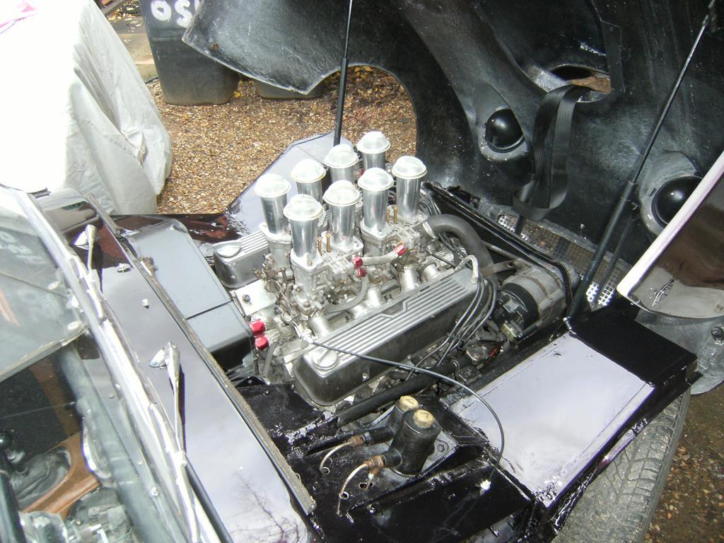 |
| |
Last Edit: May 13, 2018 21:18:28 GMT by flyingphil
|
|
Darkspeed
Club Retro Rides Member
Posts: 4,878
Club RR Member Number: 39
|
The Flowbench thread.Darkspeed
@darkspeed
Club Retro Rides Member 39
|
|
|
I'm not a carbie man, so the numbers don't mean much to me, but the ability to measure head porting or manifold porting would be interesting. Not that I'm an engineer or have the slightest clue about air flow/fluid dynamics, but I always thought that standard, mass produced manifolds could be made so much better by getting rid of casting burrs, superfluous lips etc (I saw a Honda Civic TypeR manifold yesterday that looked like it had nearly 4mm of lip on the exhaust manifold ports that could possibly have been ground off). You do have to take care with exhausts as they need a step at the manifold face to combat reversion. |
| |
|
|
|
|
|
|
|
I'm not a carbie man, so the numbers don't mean much to me, but the ability to measure head porting or manifold porting would be interesting. Not that I'm an engineer or have the slightest clue about air flow/fluid dynamics, but I always thought that standard, mass produced manifolds could be made so much better by getting rid of casting burrs, superfluous lips etc (I saw a Honda Civic TypeR manifold yesterday that looked like it had nearly 4mm of lip on the exhaust manifold ports that could possibly have been ground off). You do have to take care with exhausts as they need a step at the manifold face to combat reversion. That is true, but as per Slipngrip's thread, Honda vtec engines are weird like that. The name brand sports exhaust currently on my friend's car already has 44mm ports with no lip, while the standard manifold has the same size port, but with a 4mm lip a couple of mm down the throat. So at worst, he goes back to the same as whats already fitted to the car. But as per this thread, if it were measurable, comparable or quantifiable then a flowbench would be able to see the difference if any. |
| |
|
|
Darkspeed
Club Retro Rides Member
Posts: 4,878
Club RR Member Number: 39
|
The Flowbench thread.Darkspeed
@darkspeed
Club Retro Rides Member 39
|
|
|
Great work - I'm looking forward to seeing how 40IDFs on IR RV8 manifolds, flow if you are going to test those soon. I also ran a pair of 38DGAS carbs on a Rover manifold..... - For the love of Car(b)s As big valve Rover heads (not ultra big) flow around 170CFM @28" and a modified 38DGAS with a 30mm choke 360CFM @28" (180CFM per choke) I would expect a 40 IDF with a 32mm choke to run 200 + CFM @28" and therefore be no restriction to the flow capacity of the head. As I have a spare stage 3 big valve Rover head in the shed it will be a simple enough task to run it on the bench with 40 and 44 IDFs with 32 34 and 36 mm chokes and see if there is any difference overall - The 45mm IDF TB offered no resistance at all. I will be putting the Honda heads - the stock and ported cylinders - on the bench as soon as I make up suitable adapters and it will be interesting for me to see if the IDF 44's flow as much at the Triumph ITB or the flow achieved by the 1-3/4 (44mm) SU/CD |
| |
|
|
|
|
|
|
|
|
Looking forward to seeing those figures...
I must confess that in my youth (well 20's),I did try to do flow testing of original RV8 heads by timing the outflow of paraffin (or was it water or petrol?)from a bore dia tin sealed to the head face and opening the exhaust valve a set amount. It was certainly crude but I did see a comparative 15% improvement with porting and valve lift changes. The car did also get into the 11's with 40DCOEs. Years and £s later with big valve SD1 heads 45 DHLAs etc I finally got into the ....mid 11s....
|
| |
|
|
Darkspeed
Club Retro Rides Member
Posts: 4,878
Club RR Member Number: 39
|
The Flowbench thread.Darkspeed
@darkspeed
Club Retro Rides Member 39
|
|
|
|
What you find a lot of the time with a two valve head and IR manifolds is that if the carb is the biggest equivalent of the valve you will not be too far out! - as a big valve Rover has a 41mm valve a 42 should be chosen. With the IDFs we have 40 and 44 so a 40 should work - With an ITB you will probably find that 90% of the valve size will do.
|
| |
|
|
|
|
|
|
|
|
|
| |
Last Edit: May 14, 2018 8:58:58 GMT by ivanhoew
|
|
|
|
|
May 14, 2018 11:28:19 GMT
|
|
Robert - I didn't realise that you had a flowbench....and there are no brass fittings with polished wood surrounds!
|
| |
|
|
|
|


 - I suspect that the IDF manifold will be a restiction at some point.

