RobinJI
Posted a lot
   "Driven by the irony that only being shackled to the road could ever I be free"
Posts: 2,995
|
|
Feb 10, 2019 11:00:15 GMT
|
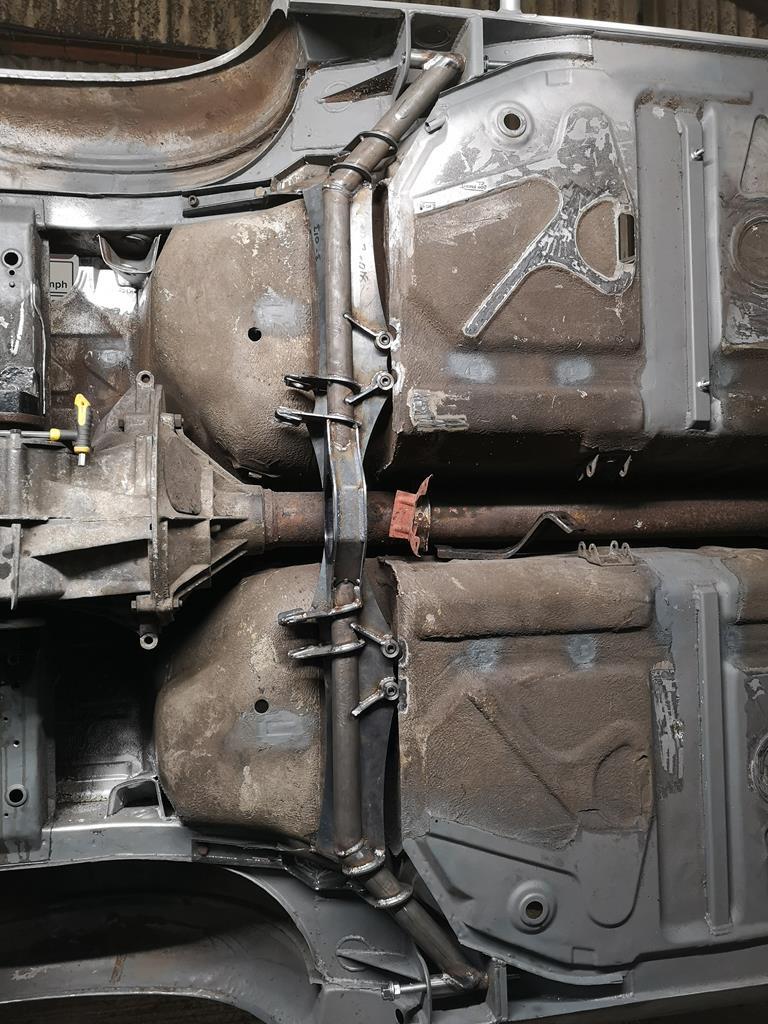
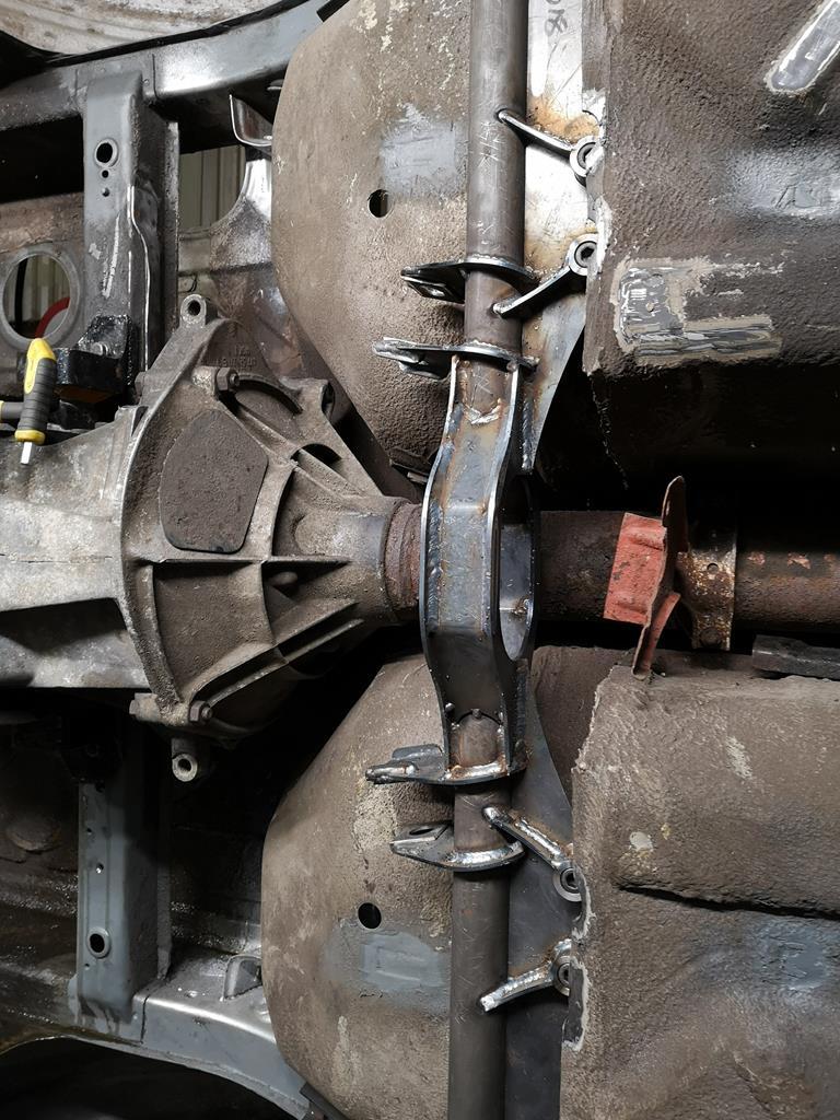
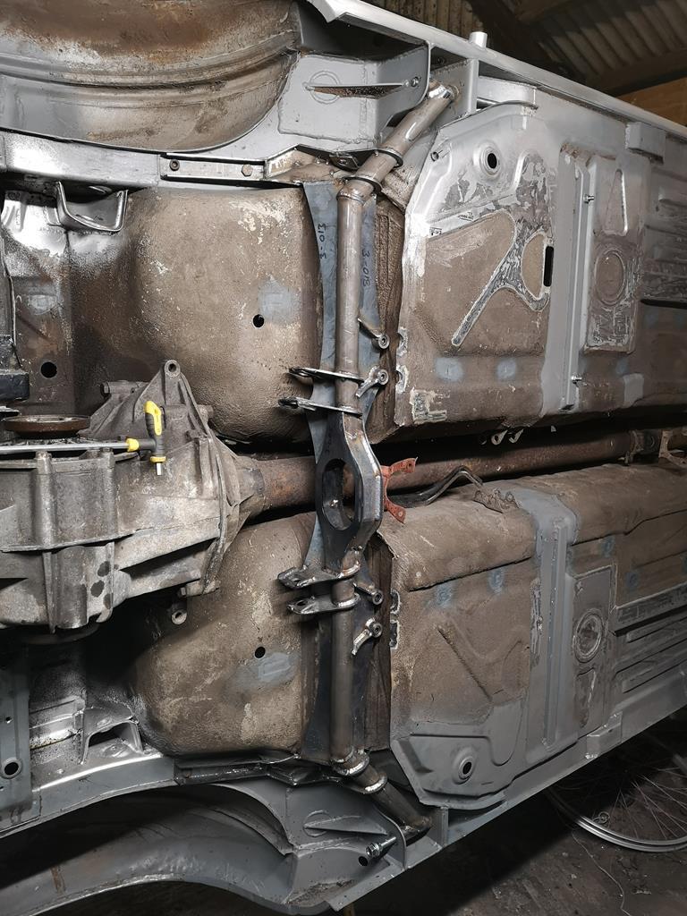
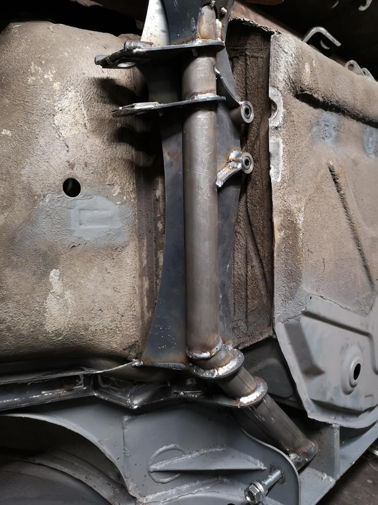
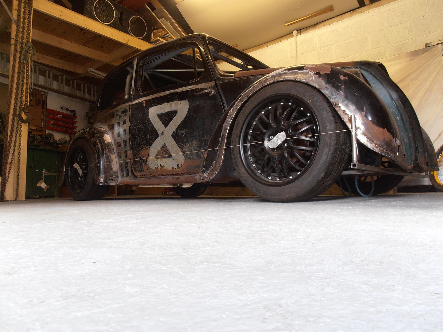
My oh my yet more brilliant and well though out work. While checking you seating position I was going to say. Make sure you check it while wearing your bone dome. And there it is in the photo, so I can only assume you were already wearing it  Thanks Broady. I was impressed with myself for remembering to take my helmet and steering wheel with me. It's the kind of thing I'd usually forget. With the seat in the position I settled on there's loads of headroom without the helmet, and even with my comedy sized 'XL' one on there's comfortable clearance. I managed to get a little time in Friday evening and yesterday and made a good start on the rear subframe (any further seat stuff can wait, getting it on wheels is highest priority right now.) I built a jig to locate the rear trailing arm mounts as they're not as easy to measure on the car as the front subframes critical dimensions were. The jig fixes their positions in space so I can build the rest around them. 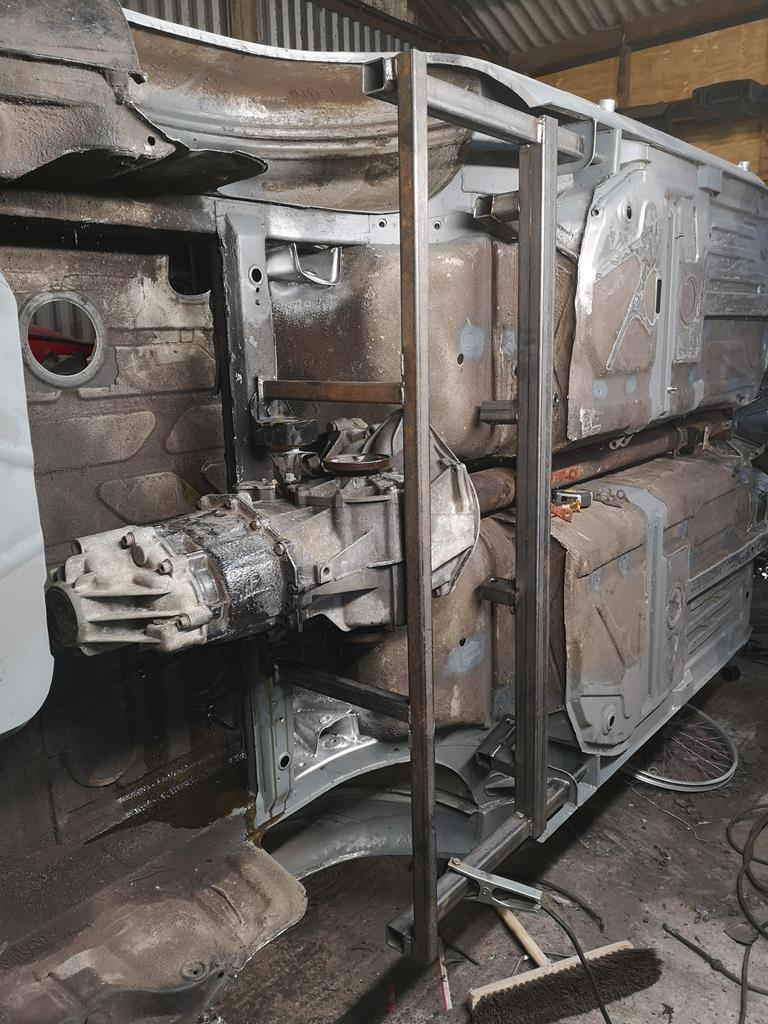 Then I've been adding in the laser cut parts along with a couple of lengths of tube with mitred ends: 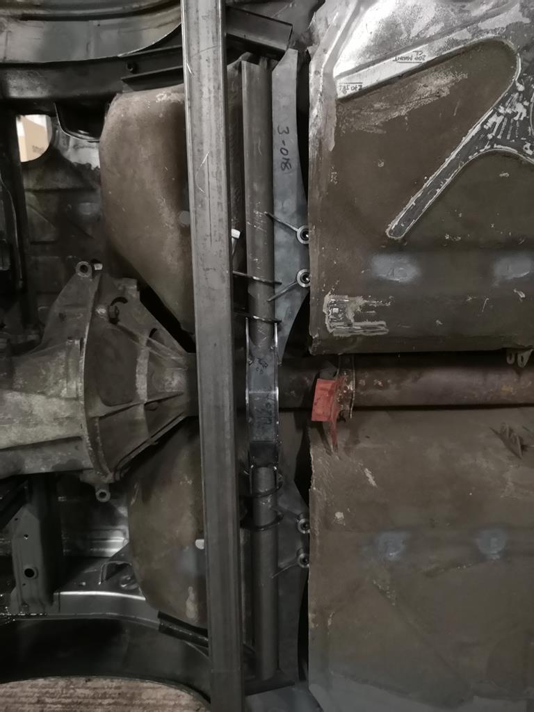 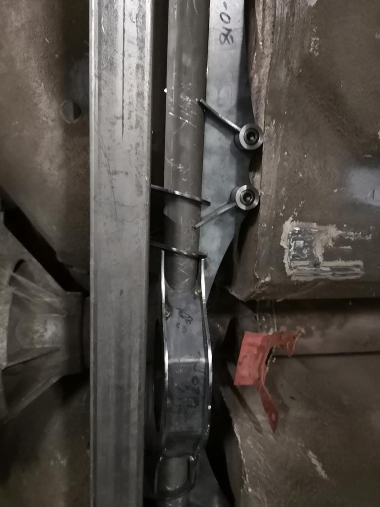 Unfortunately those terrible photos are the best I managed. Its hard to see much as the jig gets in the way. More soon hopefully. |
| |
|
|
|
|
RobinJI
Posted a lot
   "Driven by the irony that only being shackled to the road could ever I be free"
Posts: 2,995
|
|
Feb 10, 2019 20:39:00 GMT
|
|
|
| |
Last Edit: Feb 10, 2019 20:48:56 GMT by RobinJI
|
|
|
|
|
Feb 10, 2019 22:05:07 GMT
|
|
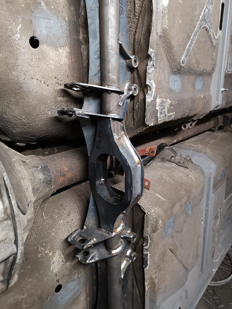
Stupid question: in your new rear subframe, there's the large center element with a big hole in the middle...what's that for? The factory torsion tube/driveshaft is above it.
Thanks for the answers re imperial vs. metric hardward. It may be apocryphal, but I think I read that during the Concorde program, the French said they wanted Bristol/Rolls to re-engineer the Olympus engines from Imperial fasteners to metric. We can imagine the words used at Filton to say "ain't gonna happen". Thanks, John
|
| |
|
|
RobinJI
Posted a lot
   "Driven by the irony that only being shackled to the road could ever I be free"
Posts: 2,995
|
|
Feb 11, 2019 10:58:43 GMT
|
Stupid question: in your new rear subframe, there's the large center element with a big hole in the middle...what's that for? The factory torsion tube/driveshaft is above it. Thanks for the answers re imperial vs. metric hardward. It may be apocryphal, but I think I read that during the Concorde program, the French said they wanted Bristol/Rolls to re-engineer the Olympus engines from Imperial fasteners to metric. We can imagine the words used at Filton to say "ain't gonna happen". Thanks, John Haha, I can imagine that wouldn't go down very well! I'm definitely a metric guy on the whole, and very much think in metric, but if there's a product that suits my needs and is cheaper and more readily available than a metric one then I'm happy enough to put up with having to divide the odd number by 24.5. It is proving to be a pain with tools though, my selection or larger imperial sockets and spanners is pretty lacking! In an ideal world I'd love to design everything around a common bolt size/head size and use that throughout as it makes working on it going forward a pleasure but I it's a lot of messing around and time. If I do end up remaking anything (funnily enough I have plans to replace this rear subframe with something a little fancier in the long run) then I'll likely put the effort in, for now though I'm compromising to get it on the road as soon as possible. A rally car I lend a hand on has M10 fine bolts with a 14mm 12 point head on everything on the front end (sump guard, wishbones, subframe, rad support, top mounts etc..) and it's amazing to work on. |
| |
|
|
|
|
|
Feb 11, 2019 15:11:46 GMT
|
Finally got round to checking this out Robin - massively impressed with your work and immensely jealous of your design skill! If you fancy a change of scenery, there's plenty to do round mine  Andy |
| |
|
|
broady
East Midlands
Posts: 408
|
|
Feb 14, 2019 18:17:04 GMT
|
More thumbs up. No further comment  |
| |
|
|
|
|
|
Feb 14, 2019 23:29:10 GMT
|
|
So what is that big circle with the hole in the middle of the new subframe for? Driveshaft? John
|
| |
|
|
jonomisfit
Club Retro Rides Member
Posts: 1,790
Club RR Member Number: 49
|
|
|
|
|
I'm going to guess exhaust. Can't see another passage for it.
|
| |
|
|
RobinJI
Posted a lot
   "Driven by the irony that only being shackled to the road could ever I be free"
Posts: 2,995
|
|
Feb 16, 2019 23:46:37 GMT
|
Thanks Broady! So what is that big circle with the hole in the middle of the new subframe for? Driveshaft? John Ah, not sure how I managed to miss answering that in my last post! jonomisfit is absolutely right, it's for the exhaust to pass through. I really want to make sure that no part of the car sits lower to the ground than the floor pans or front subframe so the exhaust will pass through there to keep it up out of harms way. |
| |
|
|
RobinJI
Posted a lot
   "Driven by the irony that only being shackled to the road could ever I be free"
Posts: 2,995
|
|
Feb 18, 2019 23:30:04 GMT
|
So a little progress. Saturday I popped out to work and gave my much neglected lathe a once over. I'd taken it into work to help with one or two urgent bits and help out my manager with a couple of things for his rally car. The lathes carriage had been getting a bit loose and the half nuts for the auto-feed were occationally disengaging unexpectedly. I'd also been meaning to modify it to add a proper carriage lock, as the only way to lock it when facing was to take the auto-feed out of gear and engage the half nuts, but it doesn't lock very solidly that way. Nothing to tell about it really, I took it apart, cleaned stuff up and reassembled it with care over the various adjustments. As for the carriage lock, a drilled and counter-bored hole in the carriage and a chunk of bar acting as a t-nut (in the channel the tail-stock locks with) seems to do the trick well. 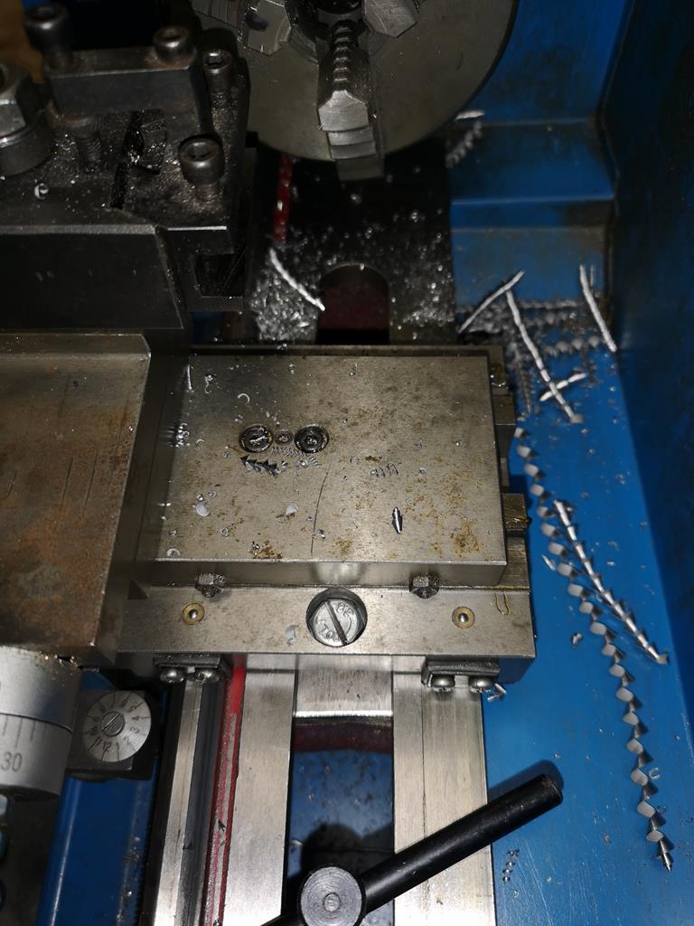 Excuse the bodged hex bolt with a slot cut in it! There weren't any long enough cap heads in the workshop and I know I've got some at my unit, so it's very much temporary! The lathe was definitely happier once it was back together, the carriage lock's great when facing and everything being tightened up has definitely brought it back from shonky-ness. Sunday I popped out to the unit, flipped the car 180 degrees and welded the opposite parts to those I did last weekend. I unbolted and removed the subframe and went to weld the top side but immediately ran out of gas so had to leave it there. 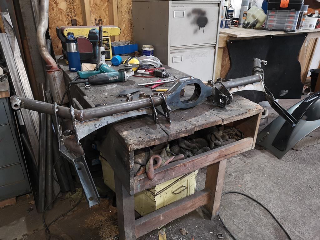 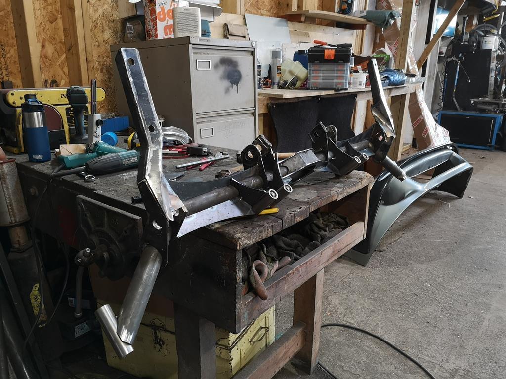 There's a couple of extra gussets (because clearly there's a lack of them so far  ) but other than the welding it's mostly there. |
| |
Last Edit: Feb 18, 2019 23:41:24 GMT by RobinJI
|
|
|
|
RobinJI
Posted a lot
   "Driven by the irony that only being shackled to the road could ever I be free"
Posts: 2,995
|
|
Mar 14, 2019 21:12:30 GMT
|
A little bit of an update: I finally managed to get some welding gas and decided to distract myself from the subframe briefly by getting the rear bearing carriers sorted. I had a pair of mk1 Audi S3 front uprights kicking around from an old project which I'd decided to use the centre section of as a pre-machined bearing housing. I did try and swap them for mk4 golf or audi A3 ones as the S3 items make a nice upgrade for the lower spec cars if they're lowered, as they have the geometry corrected for the lower ride height of the S3. Sadly it got to a point where it wasn't worth my time so I just butchered the S3 ones. The first job was to get the drive flanges out of the uprights to give me space to get in and cut off the superfluous bits. I thought the was a good excuse to finally make a press frame to work with the porta-power I own but never use. I'd grabbed some really heavy duty steel from the scrap bin at my old work (with permission) when some stuff got ordered wrong and thrown straight in the scrap. Some of it was used to reinforce the doorway of the unit and add some security, and the rest I'd kept with a press frame in mind. It's massively overkill for the 10 tonne ram of the porta-power, but it was free, so who cares. At least if I ever decide to get a bigger ram it'll be up to the job with a tweak or two: 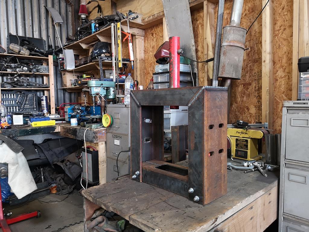 Which let me squish out the drive flanges to be left with a pair of these: 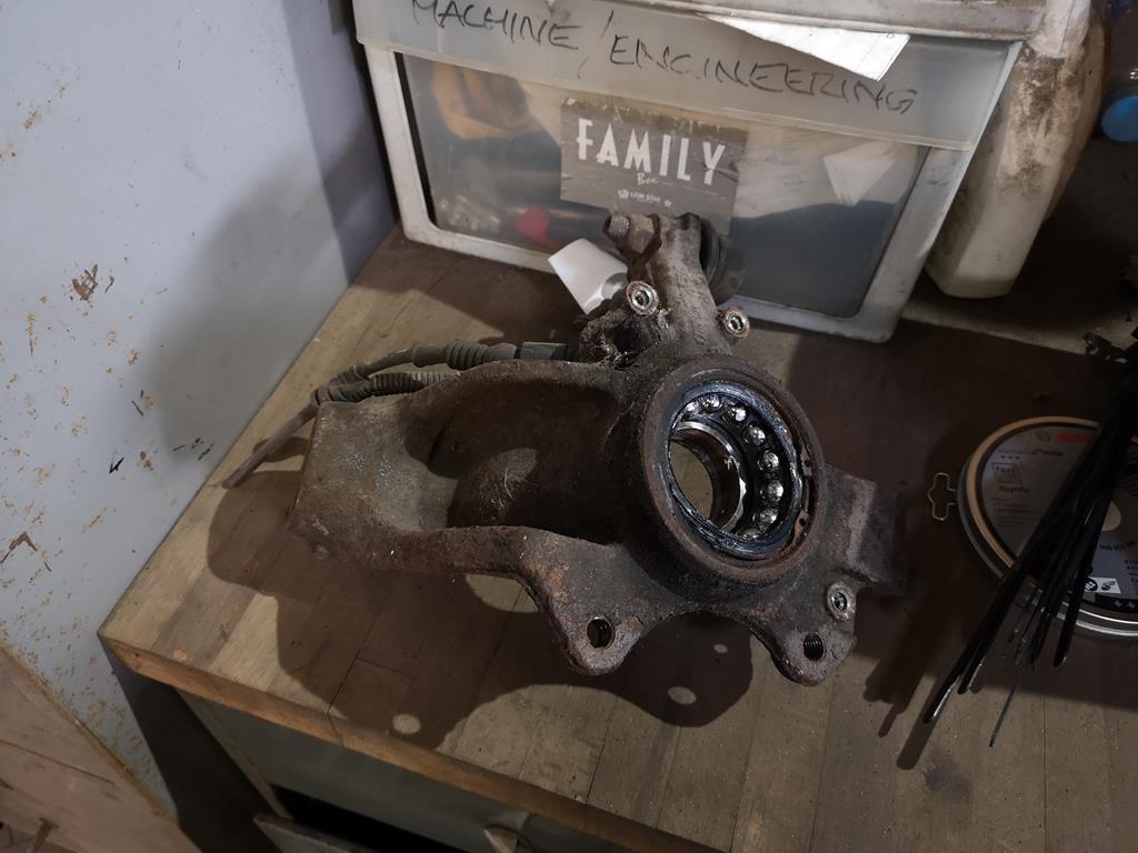 A while with an angle grinder later: 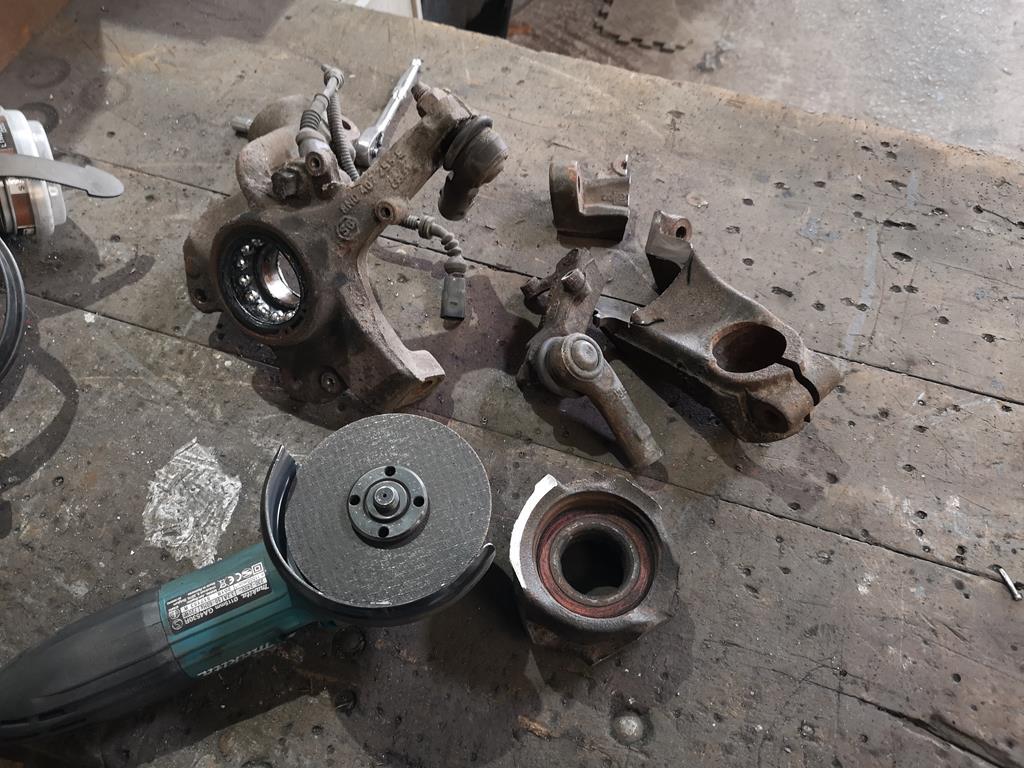 Then a while in the lathe to take all the unwanted features off, and just leave a lip at the rear edge 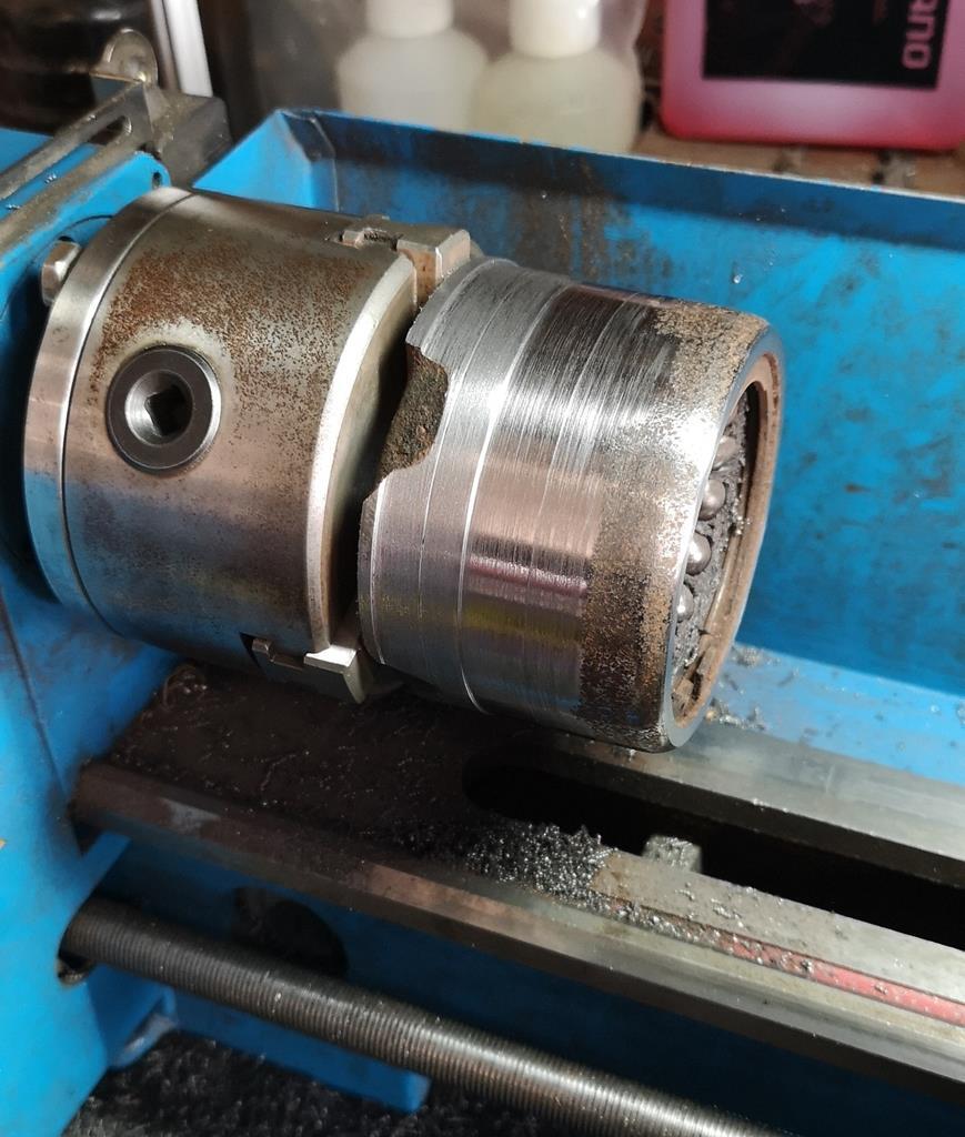 Tap a laser-cut profile over it up to the lip, weld the hell out of it, then press out the old bearings outer race, repeat the lot as a mirror image and you're left with a pair of these: 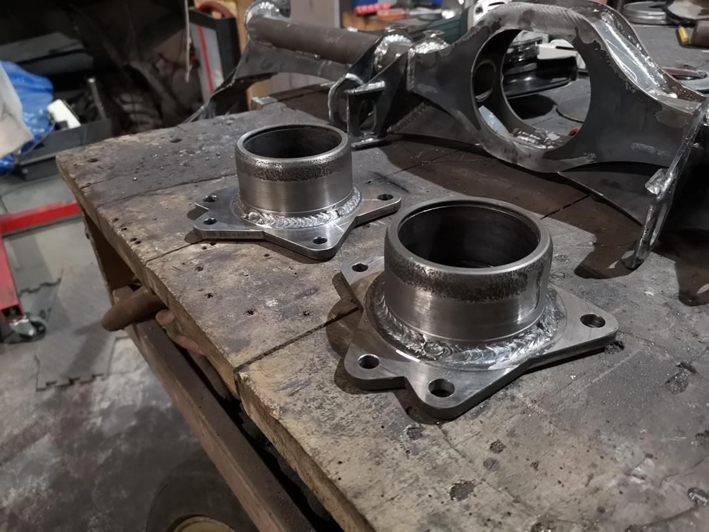 I left the bearings in until after the welding to try and minimise distortion and it seems to have worked, they certainly appear to still be round and parallel sided but I don't have much in the way of specialist bore checking kit. Once the initial corrosion was cracked the old bearings pressed out very smoothly, hopefully the new ones will go in similarly. The welds are actually kind of behind the bearing and I haven't taken it back very thin, so hopefully haven't messed up their shape. With those done, I welded the rest of the rear subframe before starting fun and games with a few strategic cuts and welds to get it back to the shape I wanted it, as the heat of welding all the top surface without it supported by the cars shell warped things a fair bit. In hindsight this was obviously going to happen, the design's very weld heavy and it was probably a mistake to weld one side in place and the other unsupported as it encouraged it to all banana pretty badly. I'm happy I've got it back how it should be now though and no weaker thanks to careful thought of where to make the nips and tucks. I should have got some shots while doing the tweaks but I was in a head-down-get-on-with-it mood with headphones on and didn't think to take photos: 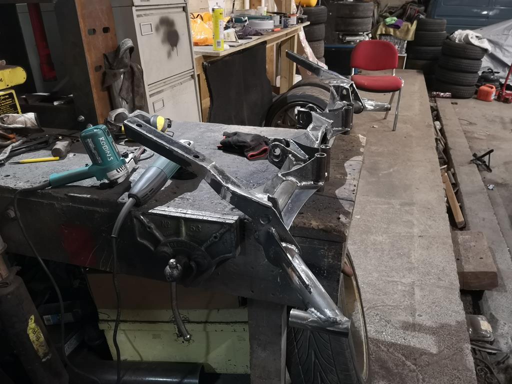 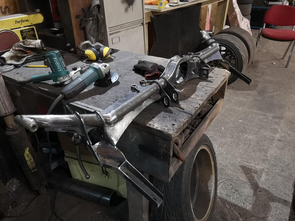 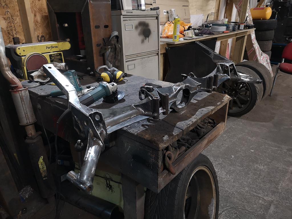 I think the end result looks quite cool, it's a shame it'll all be hidden under tatty bodywork. The next job for the back end is to make the bits that will join what I've done already: the rear arms. Speaking of arms, I also found time to send some of these off to our friendly local laser cutters: 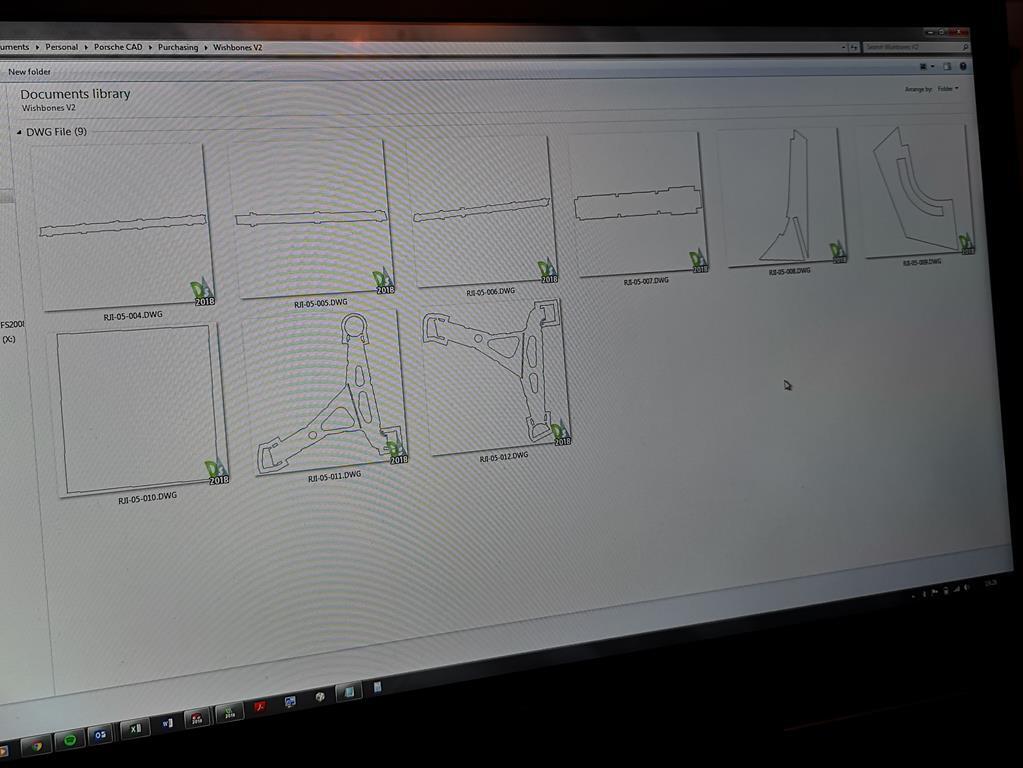 Which allowed me to collected this little lot earlier today: 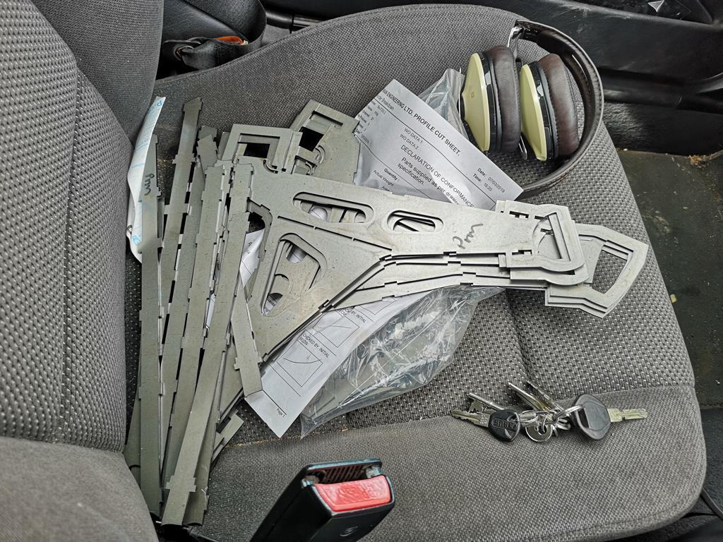 Those will let me have another go at the front arms, this time with the M18 lower ball joints matching the strut inclination angle from the word go, instead of the 5/8th ones mounted horizontally the old ones were cut to suit. The eagle eyed of you may notice that there's actually the parts of the 3 arms there. I thought this time I'd get enough done to have a spare in case anything goes wrong with the first. So I'm now 4 arms and one front upright away from being able to put the car down on 4 wheels, I'm genuinely excited by that thought, I think it's been 2.5 years since I first cut up the original front subframe and killed the possibility of having 4 wheels fitted at once! |
| |
Last Edit: Mar 15, 2019 7:50:50 GMT by RobinJI
|
|
|
|
|
Mar 17, 2019 18:40:24 GMT
|
|
genuinely interested (not critical!) about welding cast steel steering knuckles, as i have to do it.
|
| |
|
|
RobinJI
Posted a lot
   "Driven by the irony that only being shackled to the road could ever I be free"
Posts: 2,995
|
|
Mar 18, 2019 22:24:32 GMT
|
genuinely interested (not critical!) about welding cast steel steering knuckles, as i have to do it. To be honest I probably didn't think about it as much as I maybe should have, but after the fact I'm happy they're well stuck on there. Most importantly they do seem to be cast steel not cast iron; they're not brittle, they spark like steel and they give off curly 'cuts' of swarf, not just powdery chips. That's from memory though and I must admit I wasn't looking out for whether they were iron or steel, I'd just assumed that they would have used steel for a part like this, you've got me thinking I should double check on some of the off-cuts before I put them into any use. I did do a little test weld on the off-cuts and when I attacked it with a hammer it broke through the weld before the metal of the part. I kept a close eye out for any oddness around the weld but it seemed quite normal. On the back face the edge I was close to burned back just like I'd expect and the pool seemed to flow into the housing fine. I managed a bit more over the weekend. I stuck together the second upright: 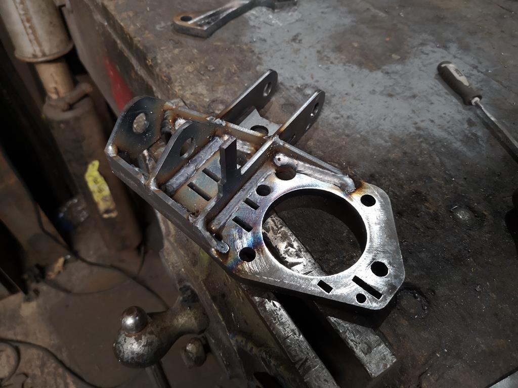 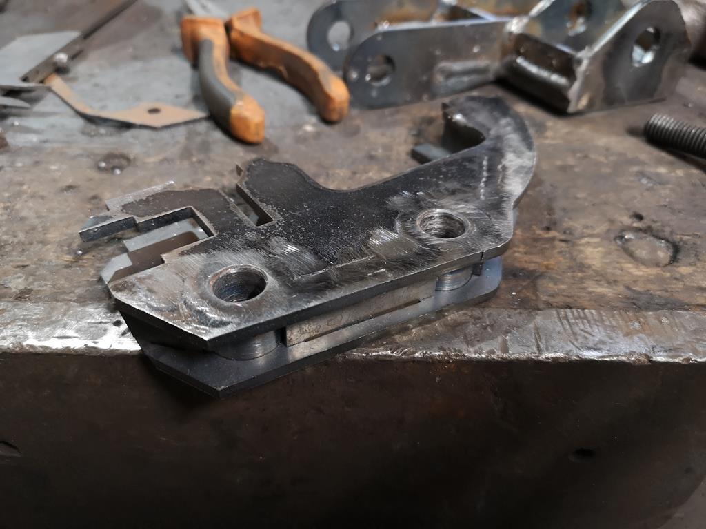 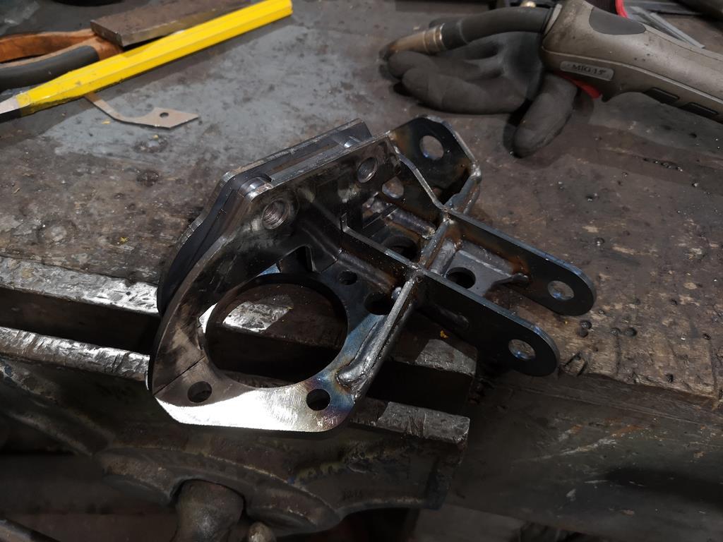 Then although I forgot to take any photos of the process I repeated the chopping up that I'd done on the other side to angle the balljoint to face the top mount. Then I cleaned up the track rod end adapters I'd made ages ago for the front subframes 'plan a' which was abandoned before this thread started. In the end these turned out to be right for the new set-up too. They're M14x2 one end and left handed 5/8th UNF the other end, with a hex in the centre and a fair bit of length to make up for how much narrower an escort is than a 924. A few seconds in the lathe with some emery cloth and they're looking good again. Finally I threw a little primer on them and uprights as well as the rear subframe to keep them from going orange:  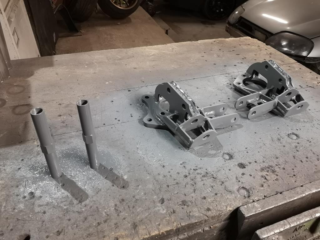 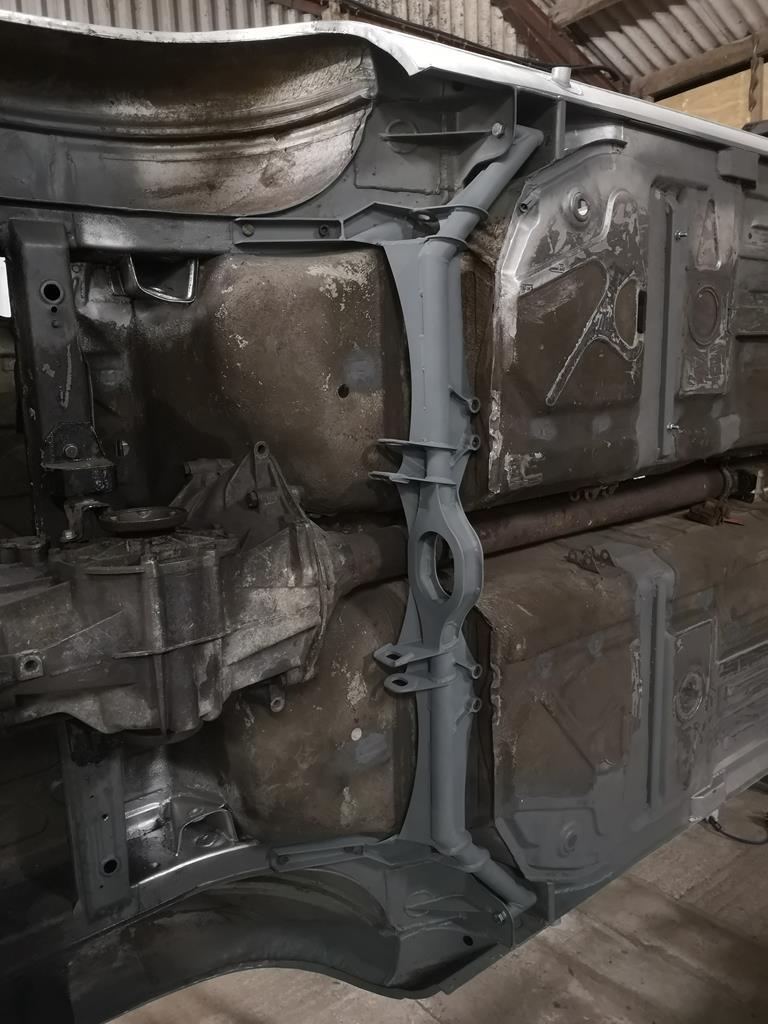 |
| |
|
|
broady
East Midlands
Posts: 408
|
|
Mar 19, 2019 21:10:16 GMT
|
|
Coming together very nicely. Certainly closer to the end than the beginning now.
|
| |
|
|
jamesd1972
Club Retro Rides Member
Posts: 2,922  Club RR Member Number: 40
Member is Online
|
|
|
|
|
Could I ask where you get your laser cutting done ? Can't be a million miles from me (near Wells) but been quoted a stupid amount of money for a cut piece of 1mm sheet so time to investigate options.
How's progress anyway?
James
|
| |
|
|
|
|
|
|
|
|
Exceptional. Really enjoy this thread.
|
| |
|
|
RobinJI
Posted a lot
   "Driven by the irony that only being shackled to the road could ever I be free"
Posts: 2,995
|
|
|
|
Thanks Broady and Oioisavaloy. Could I ask where you get your laser cutting done ? Can't be a million miles from me (near Wells) but been quoted a stupid amount of money for a cut piece of 1mm sheet so time to investigate options. How's progress anyway? James All the bits in this thread have been done by Luffman Engineering, who are based just off junction 27 of the M5, so the wrong side of me for you unfortunately. There's a couple of bigger guys in Bristol (SSC Laser and Precision Profiles), but I don't know how they'd take to smaller orders. For small batches Luffmans and Laser Industries (Saltash/Plymouth based) have always been good to me. I suspect all of them will have minimum orders though, and I don't know how any are with selling direct to the public. I've always put a few orders through them through work before getting my own bits done, which probably helps with the price too. |
| |
|
|
jamesd1972
Club Retro Rides Member
Posts: 2,922  Club RR Member Number: 40
Member is Online
|
|
|
|
|
Thanks for that. I probably meet to get a cad drawing of a 9” pipe going though a surface at an angle first.
We shall see. No harm in making a couple of calls. James
|
| |
|
|
|
|
|
Jun 25, 2019 18:49:51 GMT
|
|
HI Robin,
Any update's on the Porker ?
|
| |
If it doesn't fit you need a bigger hamer
|
|
RobinJI
Posted a lot
   "Driven by the irony that only being shackled to the road could ever I be free"
Posts: 2,995
|
|
Jun 27, 2019 16:56:43 GMT
|
HI Robin, Any update's on the Porker ? Sadly I've not got a whole lot done on it, life's been managing to get in the way plenty and I've struggled to dedicate any time to the car. The BMW needing some attention hasn't helped either as the few chances I've had to do stuff have been spent keeping that going. What I have managed to do is weld these two up: 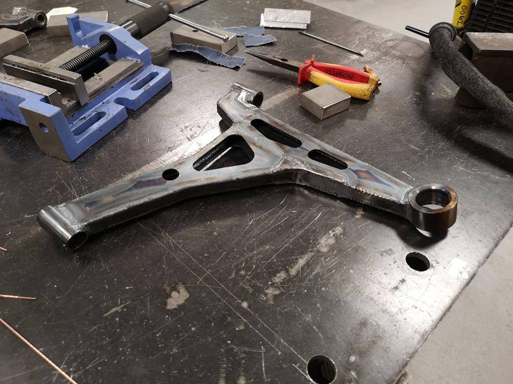 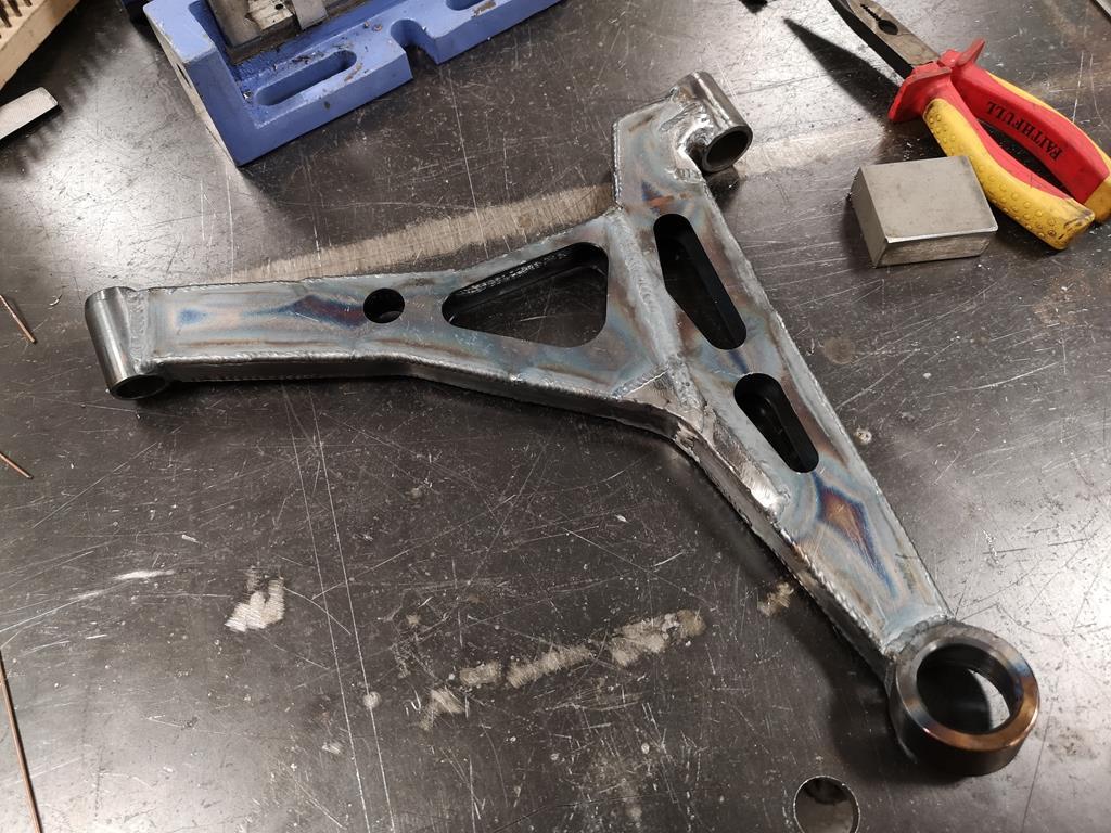 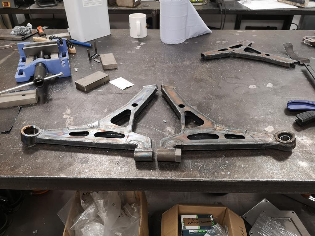 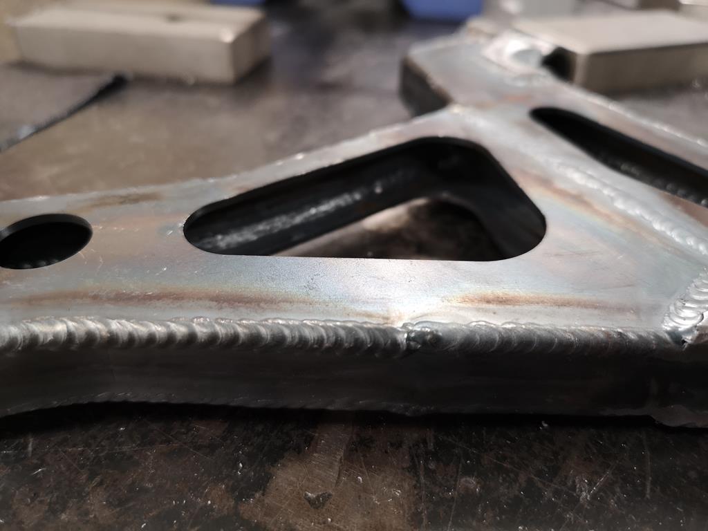 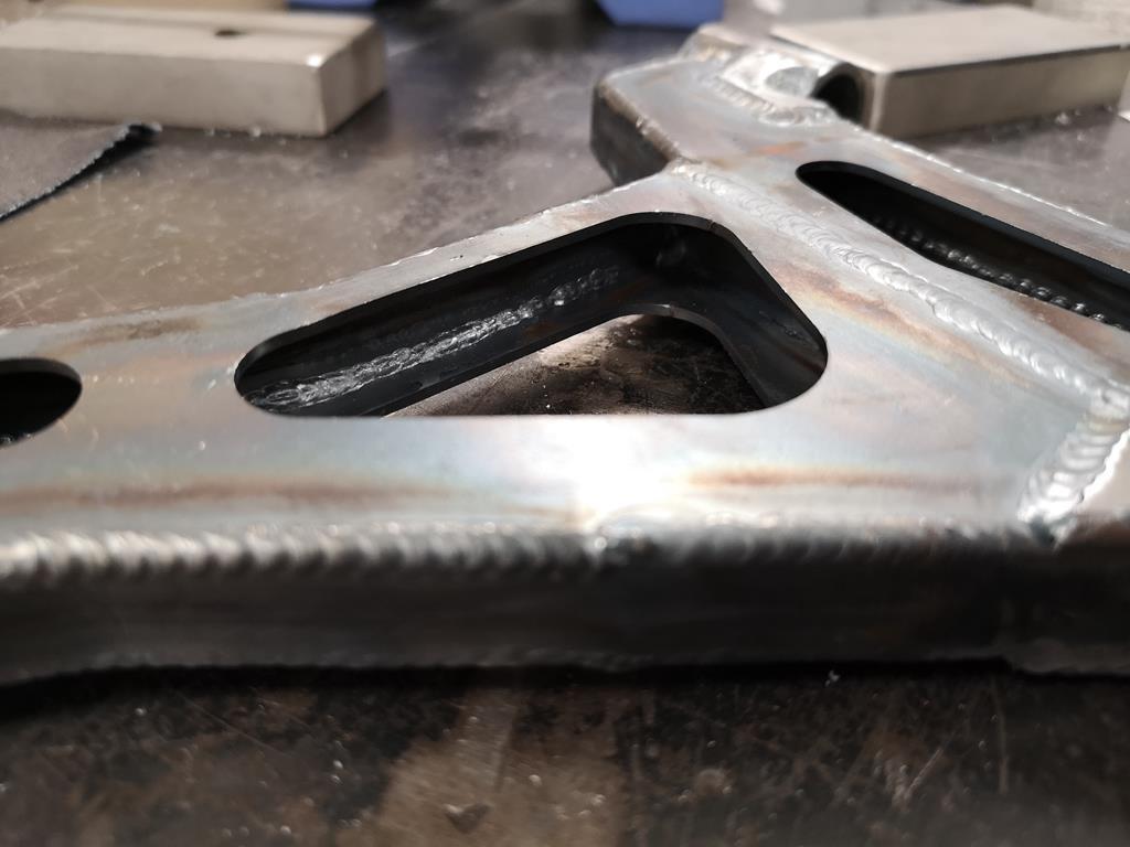 They're not the prettiest TIG welds ever, but I'm pretty happy that they're plenty strong enough. The downside is that the bearing housing for the lower ball joint has shrunk too much and I couldn't get the bearings to press into them! I'll be speaking to the machine shop we use at work to try and get them honed out to a nice press fit, but if that doesn't work I'm not sure what I'll do. My only thought was to turn up an aluminium slug to press in in-place of the bearing and remake them with that fitted while I'm welding the housing on, in the hope it reduces the distortion. I really do need to pull my finger out with it. |
| |
|
|
|
|


