logicaluk
Posted a lot
   Every days a school day round here
Posts: 1,373
|
|
Jul 10, 2024 20:20:15 GMT
|
Here is a raw data dump.  biscuits, I'm going to have to redo the exhaust numbers as i didn't reset the valve clearances to 0.15mm to check against the Haynes manual, but what clearance is usually used for producing cam data, I would guess 0 as it would give the most impressive numbers. The Haynes book of lies says with the valve set to 0.15mm clearance and in between points where the valve is 1mm off the seat inlet opens at 10°ATDC inlet closes at 30° ABDC Exhaust opens at 40° BBDC Exhaust closes at 10° BTDC The std setup marks on the cam pulley = TDC On my engine, the head has had a 1mm skim to raise the compression ratio to around 9.5:1 this has retarded the cam by 1.2°. It also has a Newman Cams uprated reground cam shaft. the following numbers were taken with valve clearances set at inlet 0.15mm (6 thou), exhaust 0.19mm (8 Thou) the cam set up marks are at 12° ATDC Inlet Starts to open at 14° BTDC Opens 0.1 at 8° BTDC Opens 1mm 11° ATDC Fully open 9.63mm at 110° ATDC / 70° BTDC Starts to close 115° ATDC / 75° BBDC Closed 1mm at 139 BTDC / 41° ABDC Closed 0.1mm 100° BTDC / 80 ABDC Closed at 82° BTDC Exhaust Starts to open at 120° ATDC / 60 BBDC Opens 0.1MM at 128° ATDC/52°BBDC Opens 1MM at 142° ATDC/38°BBDC Fully open 9.65MM at 124° BTDC/ 56° ABDC Starts to close at 94° BTDC/ 86° ABDC closed 1mm at 4° BTDC closed 0.1mm at 24° ATDC fully closed at 50° ATDC Now to try to make some sense of it all. Dan 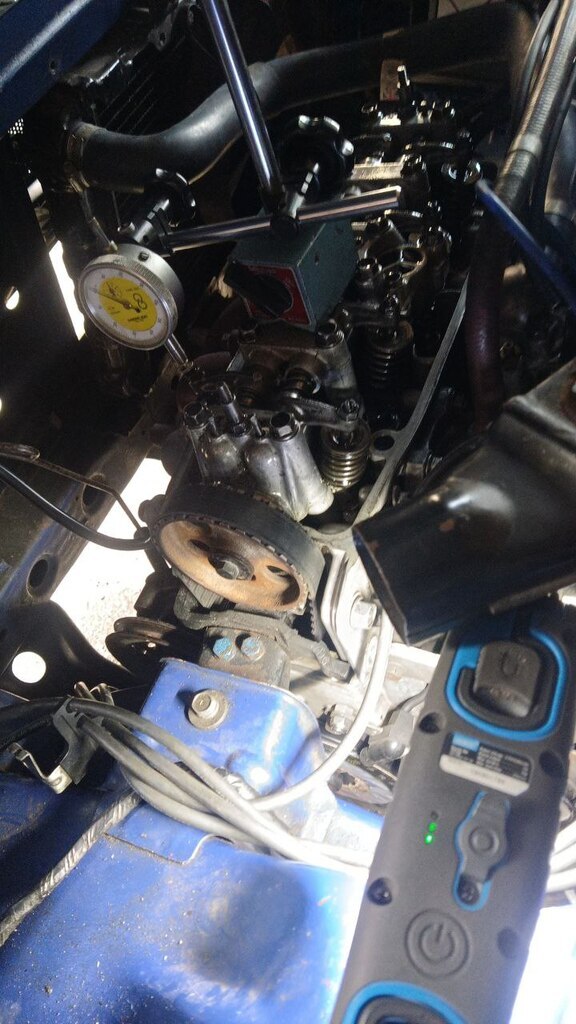 |
| |
Last Edit: Jul 10, 2024 21:46:46 GMT by logicaluk
|
|
|
|
logicaluk
Posted a lot
   Every days a school day round here
Posts: 1,373
|
|
Jul 10, 2024 21:00:11 GMT
|
|
My first pass over the data, if I take the data as good with the current valve clearances
Absolute timing events are 32-66-78-32 which puts this in the 280-290 duration area. (I equalled the inlet opening and exhaust closing numbers to get to these numbers)
If you know more about cam shafts than me, which won't take much, please chime in.
Dan
|
| |
Last Edit: Jul 10, 2024 21:29:18 GMT by logicaluk
|
|
logicaluk
Posted a lot
   Every days a school day round here
Posts: 1,373
|
|
|
|
|
Second pass on the data, from what I've read the starting point for setting up and testing is to equal the inlet opening and exhaust closing on TDC, BUT which numbers to use, the just off seat exhaust closing numbers don't look right, 0.1mm Vs 1mm come to different points 0.1mm 8° 1mm 3.5°
|
| |
Last Edit: Jul 11, 2024 11:26:15 GMT by logicaluk
|
|
|
|
|
Jul 11, 2024 16:26:01 GMT
|
|
The cam manufacturer would state at what lift the measurements should be taken. In order to assess the fully open positon, measuring the full lift with the DTI isn't accurate, you have to measure a few tenths of a mm either side of the peak (DTI reading same numbers) and take a point halfway between the two.
Using your 1mm numbers throughout:-
According to the Haynes numbers, your standard cam gives full inlet open position (inlet centreline, halfway between 1mm opening and 1mm closing numbers) of 110ATDC, assuming symmetrical valve motion. Exhaust centreline is 115BTDC.
Using your 1mm numbers for your new cam, you're somewhere around 116ATDC inlet centreline. The exhaust centreline on your new one is 111BTDC. The lobe centre angles (angle between Inlet and Exhaust Centrelines) on the old cam is 227degrees crank, which is similar to your old cam.
I might be inclined to get the new cam's lobe centrelines back to the same as the old cam by advancing it (5-6 degrees) and go from there.
|
| |
Living vicariously through other people's projects!
|
|
logicaluk
Posted a lot
   Every days a school day round here
Posts: 1,373
|
|
Jul 11, 2024 21:36:22 GMT
|
|
Thanks TG, unfortunately Newman only said to set it up on the original timing marks, and I'm not going to be able to check my mated car till next week.
I've been thinking, the valve clearances inlet 6 exhaust 8 have effected those numbers so straight after dinner I went out and reduced the valve clearance to 0, which gave these results;
inlet opens, 0.1mm at 24° BTDC. Exhaust closes 0.1mm at 38° ATDC 24+38=62/2 31, so I set the cam to 0.1mm inlet opening and the crank to 32° BTDC, found the closest keyway to it, so it's not spot on, but I certainly feels like an improvement,
ill drive it to work tomorrow and see how it feels, hopefully ill have the adjustable cam pulley made this weekend, but all the bits to build an exhaust manifold might be arriving too so I might rip the front off the car and build that instead.
When the adjustable pulley is fitted, I intend to try setting up to the original full lift center line as well as a few things to see what works, then go from there.
D
|
| |
Last Edit: Jul 12, 2024 9:11:22 GMT by logicaluk
|
|
logicaluk
Posted a lot
   Every days a school day round here
Posts: 1,373
|
|
|
|
|
My drive to work this morning was interesting, now I can hear and feel the cam come "on", it sounds like angry wasps again.
|
| |
|
|
logicaluk
Posted a lot
   Every days a school day round here
Posts: 1,373
|
|
Jul 12, 2024 17:54:41 GMT
|
After work I ran som errands, picked up 10 of these 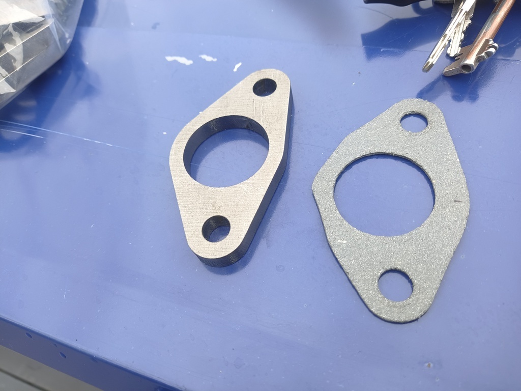 For £50 Went to the post office delivery office to pickup some parcels because the postie can't read the sign saying please deliver to number 1 if we're not in and picked up this box.  Whilst waiting for the PO to open I adjusted the timing, I've got it as advanced as it will go and still start. Which according to Des Hamills book is where it should be set. This guy seems to know his stuff as I learnt more about cams in an evenings reading than I have in 47 years. Now I have enough torque to drive at 30 in 5th gear and still accelerate. The only issue is stalling when slowing down. |
| |
Last Edit: Jul 12, 2024 18:42:46 GMT by logicaluk
|
|
logicaluk
Posted a lot
   Every days a school day round here
Posts: 1,373
|
|
Jul 13, 2024 17:43:09 GMT
|
Well as per usual, that didn't go to plan, although the pipes lined up with the flanges, all the pipes offset to the drivers side, and there's an engine support cradle there, so I chopped it up in the hope of doing something witty and clever with them and got this far. 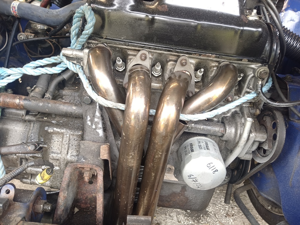 I got this far and n further as there's no way to stack the pipes that will not make the manifold the lowest point by over 30mm, and I'm not sure my fabrication skills would have been up to a full fanymould build. So seeing as I had ripped the front of the car apart I waved the last attempt at a turbo manifold at the engine. 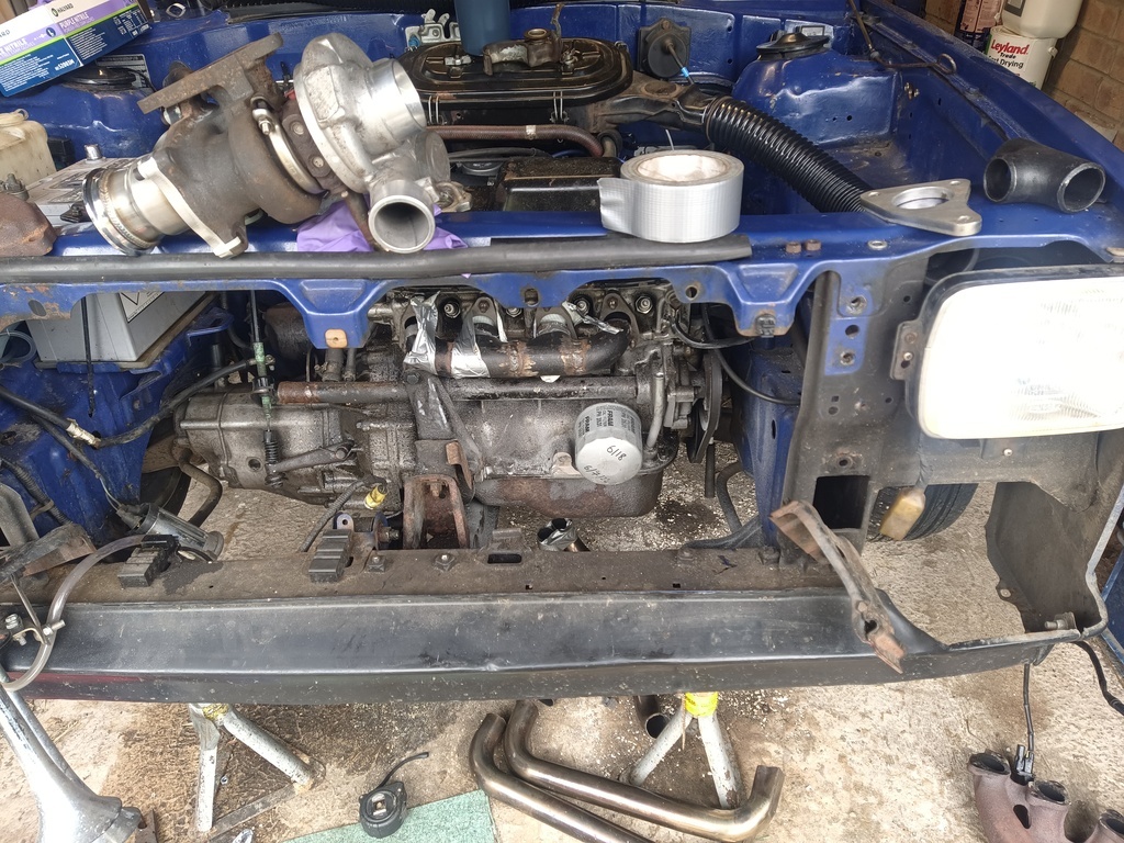 And thought about where the snail of power would fit. 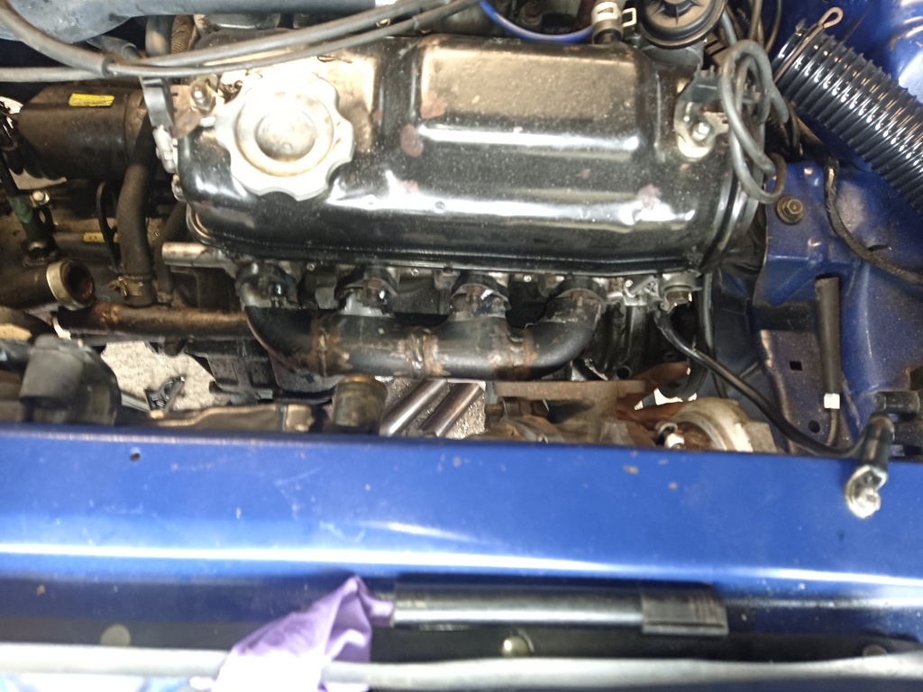 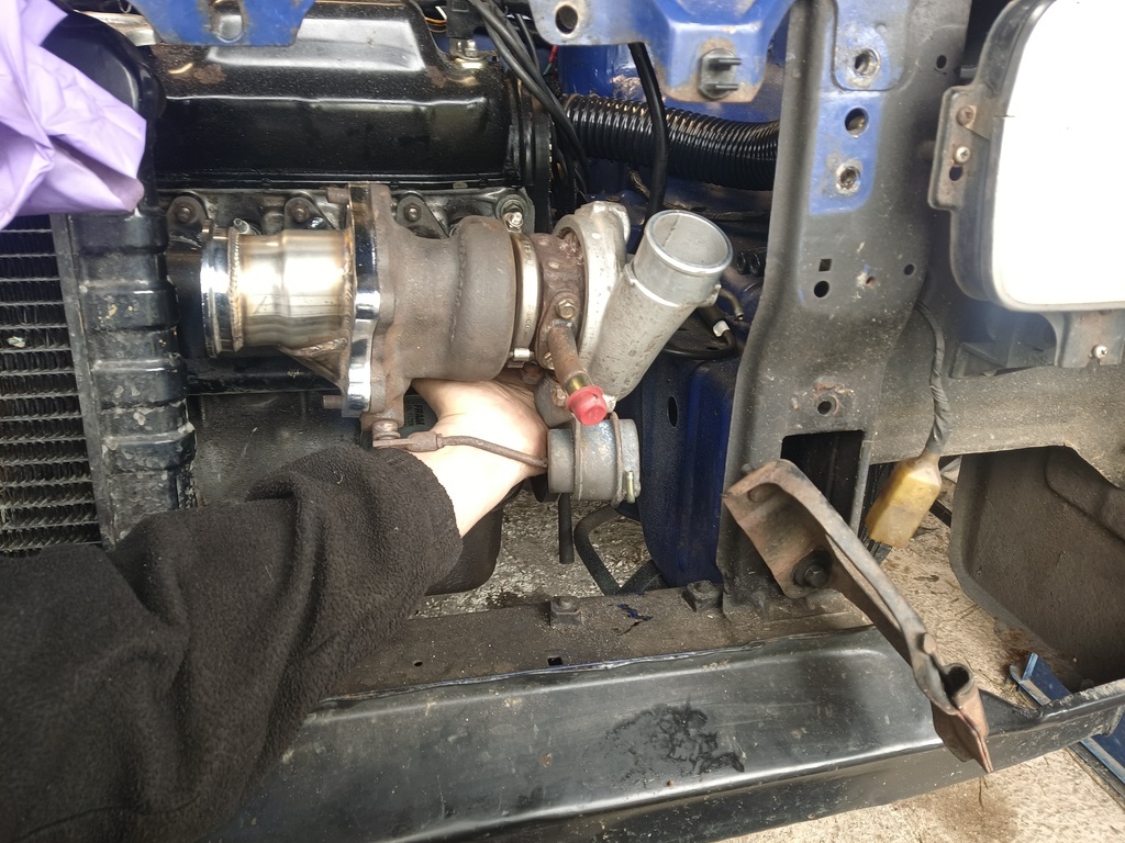 |
| |
Last Edit: Jul 13, 2024 19:11:56 GMT by logicaluk
|
|
logicaluk
Posted a lot
   Every days a school day round here
Posts: 1,373
|
|
Jul 13, 2024 19:14:38 GMT
|
|
No I'm not planning on fitting the turbo at the moment, I'm just taking the opportunity to see what fits whilst the front of the car is apart.
D
|
| |
|
|
logicaluk
Posted a lot
   Every days a school day round here
Posts: 1,373
|
|
Jul 14, 2024 17:01:05 GMT
|
Today was spent putting Frank back together, but I felt he needed a treat so I baked him a manifold. 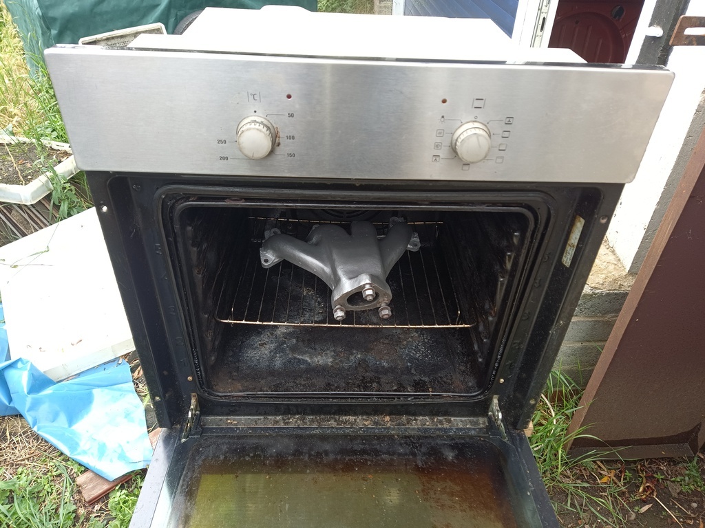 That's the original one I ported out, and changed when I was trying to make him quite. Which I blasted and gave a couple of coats of silver VHT and baked for about 40min, let's see how long it lasts for. Broke the mount for the air horn pump, which is now tiewraped to the bulkhead. Then took him out for a drive, I'm very happy, so happy in fact I gave him a new badge of honour. 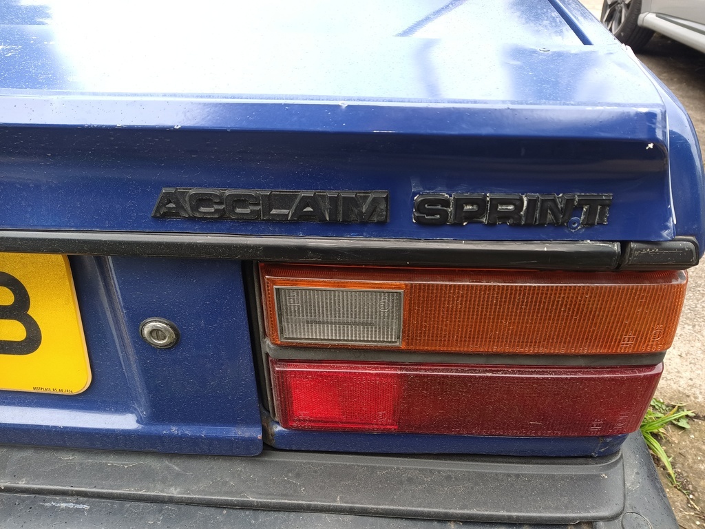 It needs cleaning to get the polish residue off. |
| |
|
|
|
|
logicaluk
Posted a lot
   Every days a school day round here
Posts: 1,373
|
|
Jul 15, 2024 21:07:01 GMT
|
I've just got back in from another spirited drive. Here are some numbers. Standard Acclaim 70 bhp, 74lbft at 3500, 0-60 13sec. Avon turbo Acclaim 105bhp, 123lbft at 3500, 0-60 9sec Frank 0-60 solid 11sec maybe a bit less. I also checked the cam timing on a standard car, with 0 clearance inlet opens 0.1mm 10° BTDC, 1MM 11° ATDC.  Hopefully next up will be the adjustable cam pulley, its all marked out, I just need to get on with it. |
| |
|
|
logicaluk
Posted a lot
   Every days a school day round here
Posts: 1,373
|
|
Jul 16, 2024 21:27:02 GMT
|
After the gym and dinner, I took my marked out ali plate to the workshop. 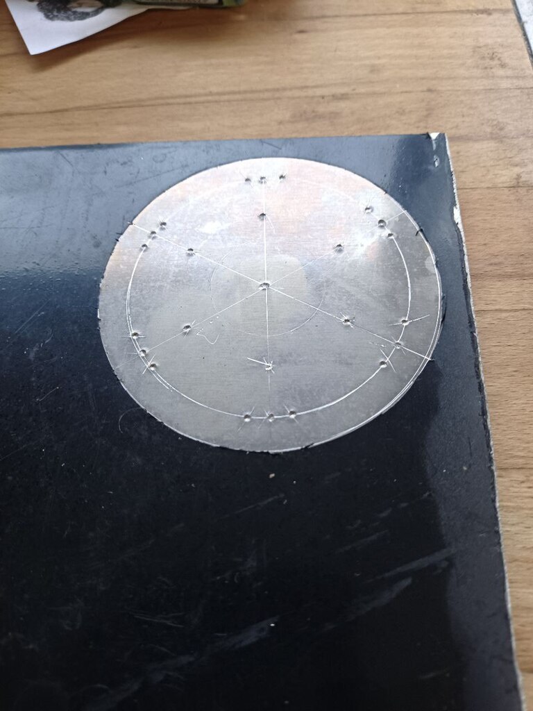 Spot carefully spot drilled it, then cut it out with a hole saw. 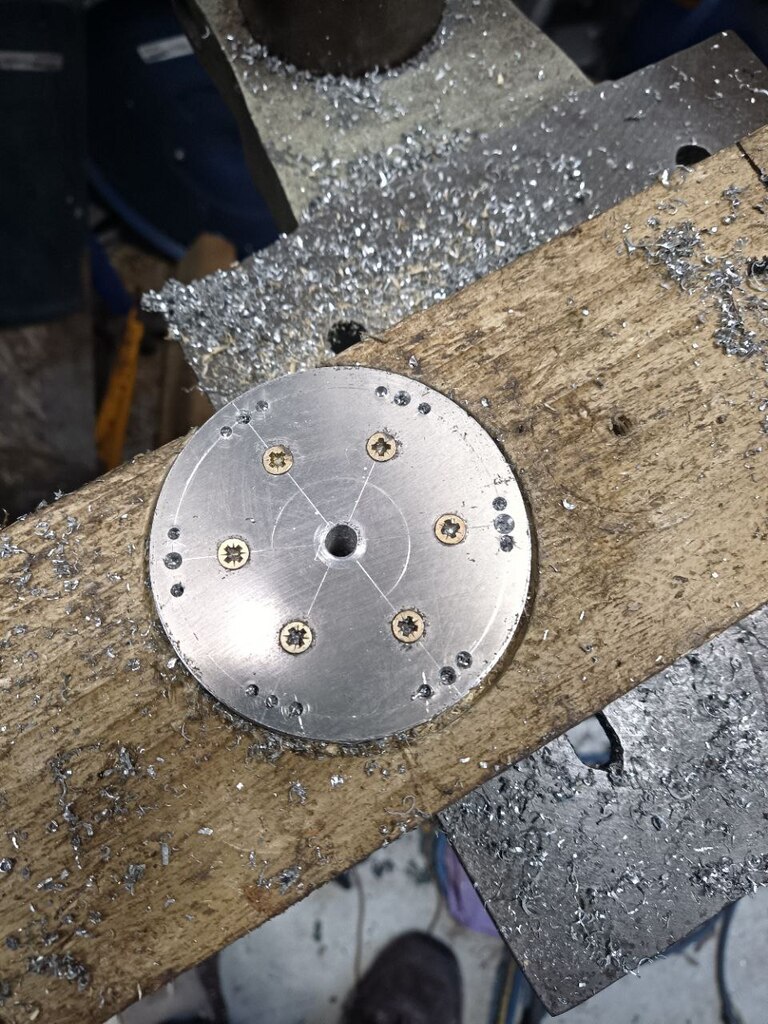 Centred it in the lathe and bored out the centre hole, trying to make it a very tight fit i didn't quite open it up far enough. 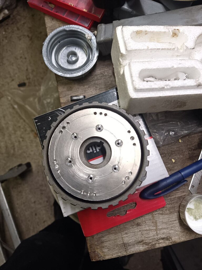 But I'm not happy with it, I stared it down for half an hour, and I think I've worked out a better way to approach it. 1 Cut out a square big enough that the outside dim can be cut out in the lathe and not touch the chuck. 2 Mark out the 6 points for drilling, use the lathe to mark out the intersections. 3 Bore out the centre hole. 4 Put the lathe in to back gear and lowest gear, mount a drill on the top slide and use it like a mill to drill out the screw holes and slots. 5 Cut the external dim and fingers crossed it should fit. 6 Use the plate to mark up the holes in the pulley, drill and tap. 7 Chuck the pulley in the lathe and separate the centre, hopefully take enough weight out of the pulley to counteract the weight of the modification. dose this make sence? |
| |
|
|
logicaluk
Posted a lot
   Every days a school day round here
Posts: 1,373
|
|
Jul 17, 2024 21:51:37 GMT
|
Plan B definitely worked better I marked out the 6 centre lines and each of the sections 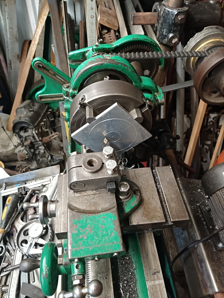 But the flexible drill shaft cacked it's self and a mighty bit of bodgery ensued. 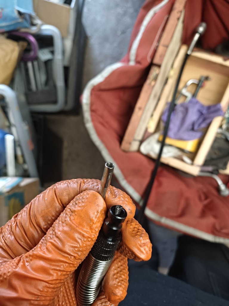 After 3 attempts I ended up cutting an M6 thread on the drive dog and locking a couple of nuts together to drive it with the drill, unfortunately I had to hack the back off the drill to make it fit 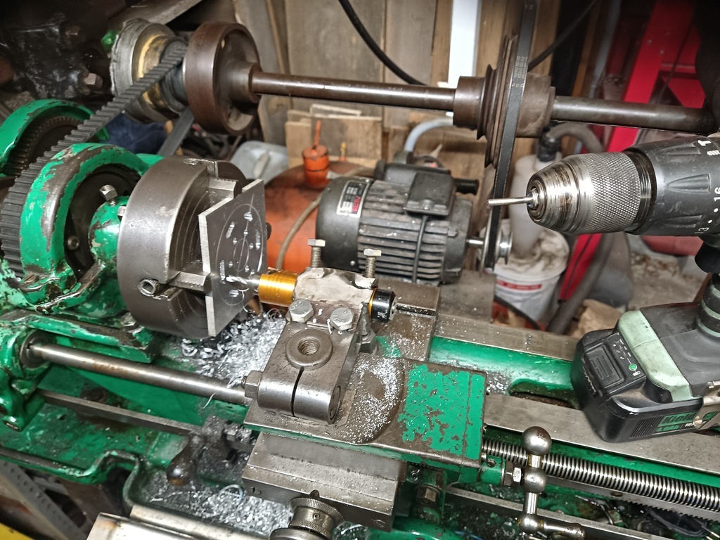 But eventually it got done, hopefully nothing a file won't cure 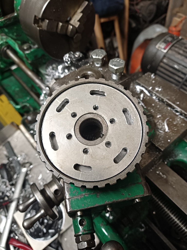 |
| |
Last Edit: Jul 17, 2024 21:56:30 GMT by logicaluk
|
|
Enbloc
Part of things
 
Posts: 400
|
|
Jul 22, 2024 17:03:14 GMT
|
|
love the lathe work for doing the slots. May well be doing this same job soon.
|
| |
|
|
|
|
|
Jul 24, 2024 10:43:59 GMT
|
|
Very clever use of the lathe! Are you going to do any balance testing? I suppose they spin at half engine speed and are pretty small radius so the out of balance forces should be small, but I remember a clever trick for home balancing (the work of either @vitessefi, or JohnD/GT6M on the Triumph forums IIRC). Find a bearing that will seat neatly into the centre hole of your part. This will cause the heavier side to drop to the bottom, the bearing being free-spinning. Shave a little bit off the bottom edge, rinse and repeat until there's no clear heavier side and hey presto! I recall it being done on a flywheel and working well, so a cam pulley should be far lower risk.
|
| |
|
|
Darkspeed
Club Retro Rides Member
Posts: 4,889
Club RR Member Number: 39
|
83 Triumph Acclaim SprintDarkspeed
@darkspeed
Club Retro Rides Member 39
|
Jul 24, 2024 17:54:41 GMT
|
Are you going to do any balance testing? I suppose they spin at half engine speed and are pretty small radius so the out of balance forces should be small, Made me think of when I had my RV8 pulley balanced with the trigger wheel - I wondered then just how many bother to correct for that missing tooth..... |
| |
|
|
logicaluk
Posted a lot
   Every days a school day round here
Posts: 1,373
|
|
|
|
Very clever use of the lathe! Are you going to do any balance testing? I suppose they spin at half engine speed and are pretty small radius so the out of balance forces should be small, but I remember a clever trick for home balancing (the work of either @vitessefi, or JohnD/GT6M on the Triumph forums IIRC). Find a bearing that will seat neatly into the centre hole of your part. This will cause the heavier side to drop to the bottom, the bearing being free-spinning. Shave a little bit off the bottom edge, rinse and repeat until there's no clear heavier side and hey presto! I recall it being done on a flywheel and working well, so a cam pulley should be far lower risk. Thanks. I had thought about the balance, but concluded that it was probably fairly well balanced to begin with, the parts added (and removed) were fairly evenly distributed, its fairly small diameter and lower speed, and considering I didn't have a way of balancing it, it was fairly likely to be good enough for the girls I go out with Frank. But now that equation has changed, ill see if I can find a suitable bearing. D |
| |
|
|
Enbloc
Part of things
 
Posts: 400
|
|
Jul 28, 2024 12:32:11 GMT
|
|
When I had my last rotating balanced I was told the trigger wheel had been removed and loosely put back.
Like an idiot I didn't ask why at the time but assume its because they don't actually balance with the missing tooth trigger wheel in place?
|
| |
|
|
|
|
|
|
|
When I had my last rotating balanced I was told the trigger wheel had been removed and loosely put back. Like an idiot I didn't ask why at the time but assume its because they don't actually balance with the missing tooth trigger wheel in place? If they're doing it the thorough way they'll balance each individual component, then bolt everything back together and correct for any minor differences. Not 100% sure that's necessary though as the whole thing operates as a unit anyway. Only really gets to be an issue when you're balancing out of balance forces at one end of the crank with ones at the other. The tell will be if there's any little drilled sections on the trigger wheel itself. |
| |
|
|
logicaluk
Posted a lot
   Every days a school day round here
Posts: 1,373
|
|
Sept 8, 2024 21:03:26 GMT
|
|
Ive been thinking, whilst I'm laid up recovering from having my appendix removed.
My thoughts have turned to the over sized pistons I have on the shelf, now to say mafs was never my strong point would be an exaggeration, so I'm hoping some kind, passing mafs genius can help me out here.
Acclaim standard specs are
72mm bore x 82mm stroke x 4 = 1335cc with a compression ratio of 8.5:1 (I have the CC of the standard head chamber written down somewhere)
Frank has a standard block with 1mm milled off the head, giving an estimated 9.5-10:1 comp ratio.
The bigger pistons are 74mm bore x 82mm stroke x 4 = 1410cc can the compression ratio be estimated with the standard or skimmed heads
But I can get +1.25 & +1.5mm conrod bearings, what if I offset ground the crank? Now if my jometry is correct (and it's considerably worse than my mafs) if the conrod journal is good enough to offset 1mm that would increase my stoke by 2mm taking the swept volume, with a huge boost in compression ratio, add all this to the learnings I got at Dark Towers and a high lift cam. I think it might be quite quick
This engine would be
74mm bore X 84mm stroke x 4 1445cc compression ratio ?
How much land at the top of the bore should I leave ?
|
| |
|
|
|
|
 biscuits, I'm going to have to redo the exhaust numbers as i didn't reset the valve clearances to 0.15mm to check against the Haynes manual, but what clearance is usually used for producing cam data, I would guess 0 as it would give the most impressive numbers.
 biscuits, I'm going to have to redo the exhaust numbers as i didn't reset the valve clearances to 0.15mm to check against the Haynes manual, but what clearance is usually used for producing cam data, I would guess 0 as it would give the most impressive numbers.


