|
|
|
Jun 10, 2015 16:08:02 GMT
|
|
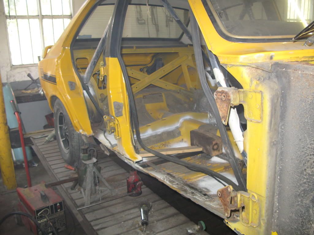
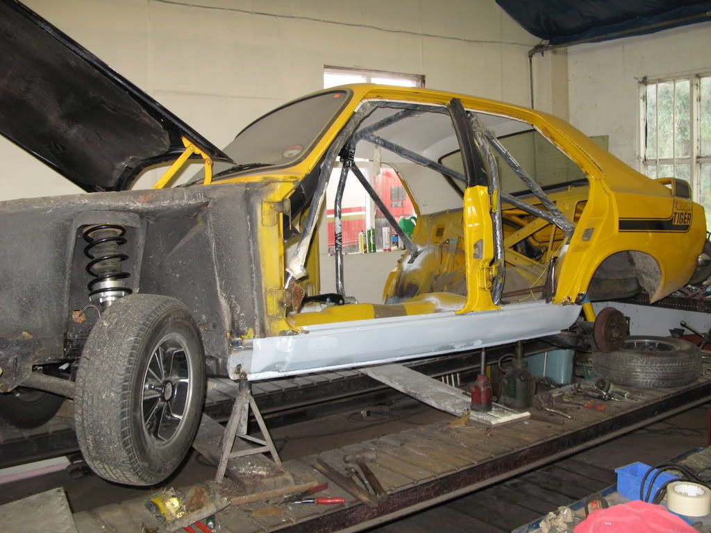
OK, this is the story - so far - of my Avenger Tiger and its journey from road car to its current state.
This is basically a copy and paste from the ASOC forum, so if you are a member i apologise for the repetition :-)
|
| |
|
|
|
|
|
|
|
Jun 10, 2015 16:14:52 GMT
|
|
Where is it?
|
| |
New cars. Who needs em.....
|
|
|
|
|
Jun 10, 2015 16:16:02 GMT
|
November 2008 Well the time has come to pay attention to my Tiger after spending a year with the Lotus. I am hoping to do the ASWMC Sprint championship with it next year and so at the begining of the year i started gathering bits for a new engine. The current one then had the head fail with one of the waterways and this ruined one of the bores. Luckily i have now picked up a really good bottom end and my old 'Hillclimb' Head is being refurbished to go on it. However, some of you may be aware i used to race a Tomcat - see the avatar - and for this i had built the engine and the ECU. I used a MS1 controlling both fuel and spark. It was an exciting project and one i was keen to do again if the chance came up. Ans as if by magic Bill Shurvinton who supplied the last kit and help got in touch to offer me one of the new Microsquirts in return for some articles he would like written. So look what came through the post this week: 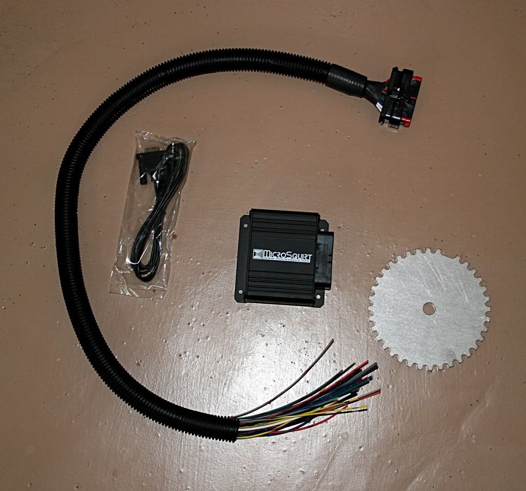 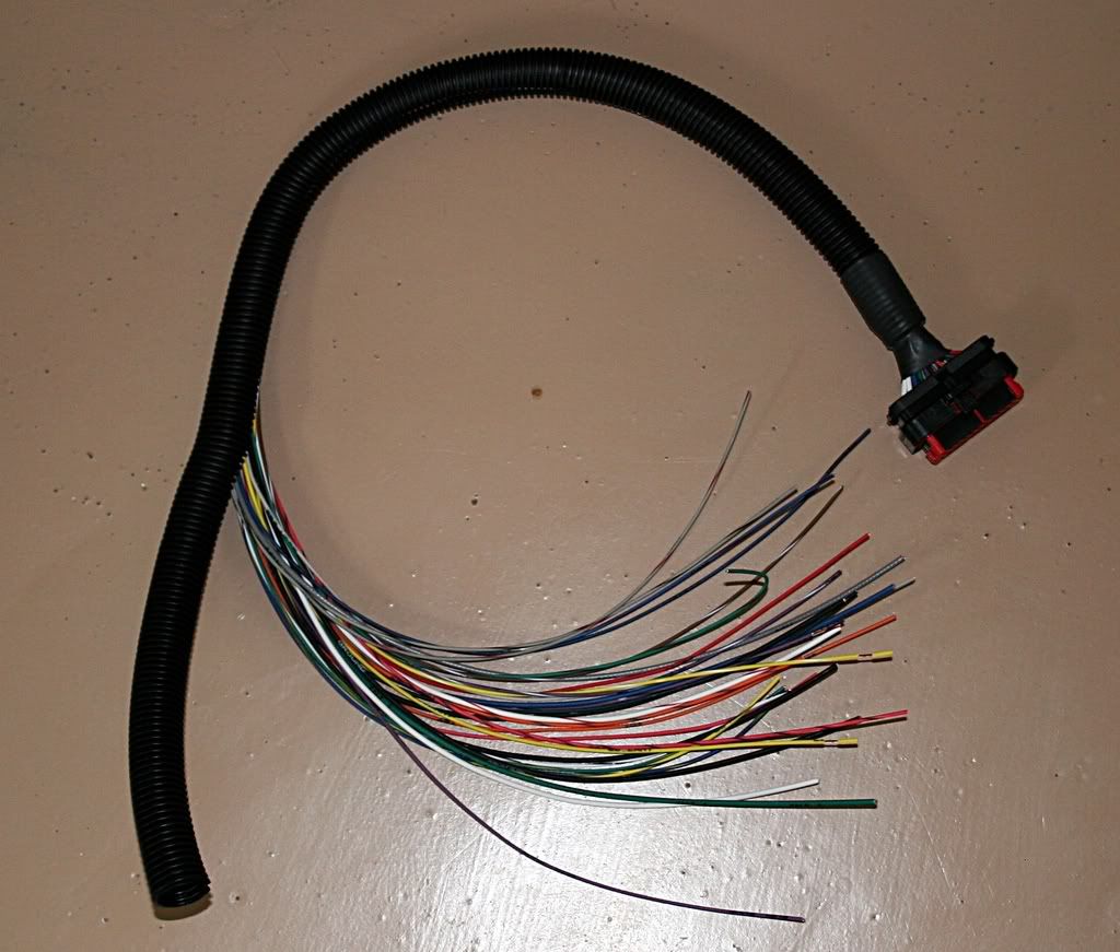 The Trigger wheel is 145mm in diameter so it shows how small the Microsquirt is! The plan is to get he new engine up and running on Carbs and Dizzy and then progressively change over first to 3D Ignition and then to Fuel Injection. This thread i am hoping will show what it has taken to instal it and tune and then see whether its worth it!!! Nev |
| |
|
|
|
|
|
Jun 10, 2015 16:16:24 GMT
|
|
The Microsquirt is basically the same as a MSII but built in SMT rather than with discrete components. The original idea with Microsquirt was to bring the world of Megasquirt to Motorbikes and Snowmobiles etc. Therefore Micro was designed to be able to support the software that MSII uses.
I have been using a version of code called Extra on my MSI and Extra for MSII will, should!, work on Micro as they are they same platform. Whether i use Extra on my Micro is something i have yet to decide on, as the standard Micro code is very powerful and will do everything i need to run the engine. However, Extra has a few extras that are very useful like Launch Control and Shift Lights which i had before on the Tomcat, but that is yet to be decided.
The differences between MSI and MSII are many with MSII using a much quicker CPU thus the resolution of the operations is much smaller making for better control.
The Microsquirt is - as Jim points out - aimed more towards those who do not want to build their own kit as the technology within Micro makes it very hard to assemble at home. However, if the Micro cost is compared to a supplied fully assembled MSII then the cost is the same. The Micro has the advantage of being fully sealed and using a fully sealed AMP style connector. This enables it to be housed anywhere within reason and not be a problem. For a normal saloon car and with some DIY soldering skills it is cheaper to go for a MSII kit as works out 2/3 of the assembled price.
My Bottom pulley and the trigger wheel seen in the photo's is now away being melded into one unit, i should get it back in the next week or two and then i can start making a bracket to hold the VR sensor on. The tricky part of getting the trigger wheel and bottom pulley together is to ensure the trigger wheel has some rotational adjustment compared to the pulley, to allow the VR sensor to line up. There is a trigger angle offset in the software but its best to get it a mechanically close as possible in my view.
|
| |
|
|
|
|
|
Jun 10, 2015 16:17:23 GMT
|
The bottom pulley we are hoping will stand being split and the trigger wheel being inbetween with some rotational adjustment. I was worried if it went on the outside that it migh be little heavy for the light weight construction of the pulley. But we shall see. In MSExtra Launch Control is done within software only on the rate of increase of RPM's. There is traction control which does use wheel sensor inputs. On my MSIExtra the launch control was even cruder in so much that it used a two stage rev limit to limit the amount of wheel spin. I am not sure whether i will be able to use that part of the Extra code as the Micro is limited on I/O with the 35way Amp Seal plug. More research is needed for that application. I got the new engine on the stand today and it all seems good apart from the cam followers which are very poor and appear not to be matched to the cam which is excellent. New followers will be used, the cam appears to be an original Group 2 as its not a re-grind like my new WRM Grp2. I measured everything up and if built up with the 'Hillclimb' head it will have a 10.3:1 CR not as high as i would like but ok for the purposes it will be used for. Nice to spend a decent amount of time in the garage for once! 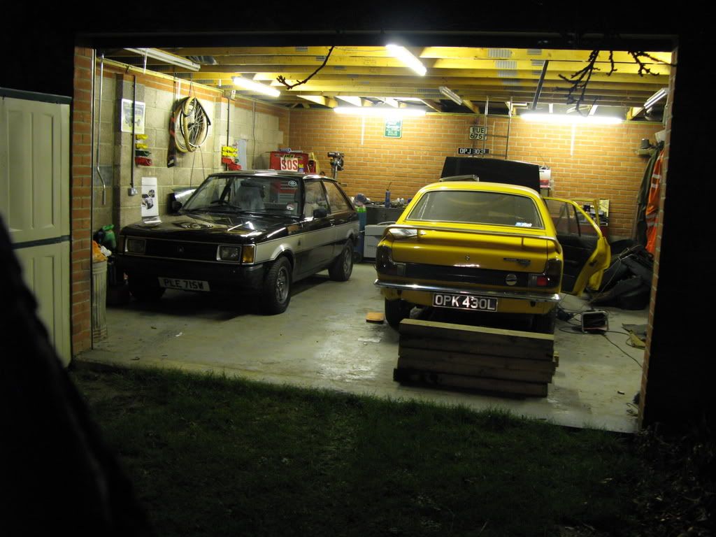 |
| |
|
|
|
|
|
Jun 10, 2015 16:18:47 GMT
|
I was at home for a day a week or so ago and managed to do some work on the Tiger. I modified the strut brace so it fitted. Built a chassis brace for the front suspension which triangulates the front end. I built the battery boxx holder: 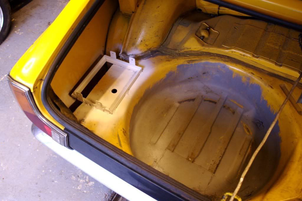 I just need to make a 'centre console' thing to go between the gearbox tunnel and the dash to mount the FIA Cut-off in. I do not have any alloy at the moment so it may have to wait. Nev |
| |
|
|
|
|
|
Jun 10, 2015 16:19:32 GMT
|
|
|
| |
Last Edit: Jun 10, 2015 16:20:14 GMT by nevtiger
|
|
|
|
|
Jun 10, 2015 16:22:49 GMT
|
I picked up the head that i will be using on my interim engine until my Heikki head comes. This was done a casting that had been modified about 15yrs ago from a new casting and had been used in my Hillclimb Ti. I wanted it overhauled with new guides etc. Bryan Slark of SRE had a really good go at the head and now the ports are a very much different shape and size. An inlet manifold was matched at the same time. It ended a bit more than an overhaul........... Here is a shot of the chamber and the 1.7" Fiat inlet valves. 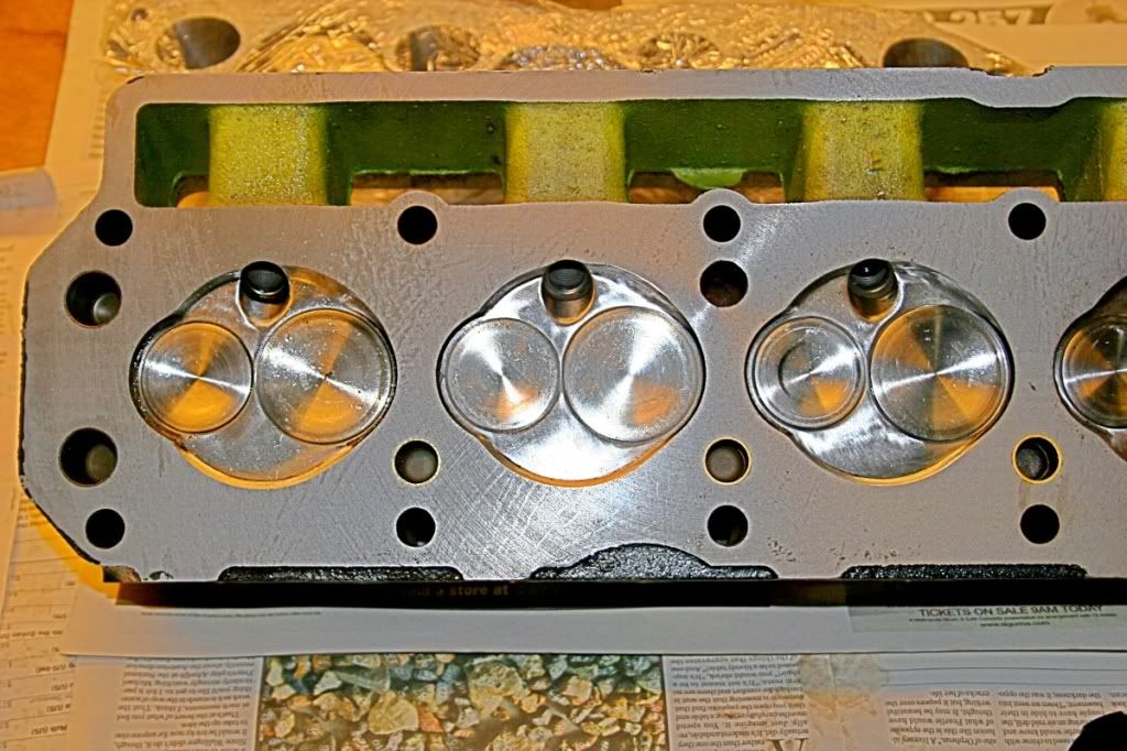 And now a shot of the inlet and exhaust ports 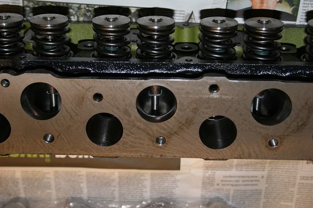 This should be getting introduced to the rest of the engine over the Xmas break! (this was written in 2008 December) Nev |
| |
|
|
|
|
|
Jun 10, 2015 16:25:01 GMT
|
I also picked up my modified front pulley now with toothed wheel 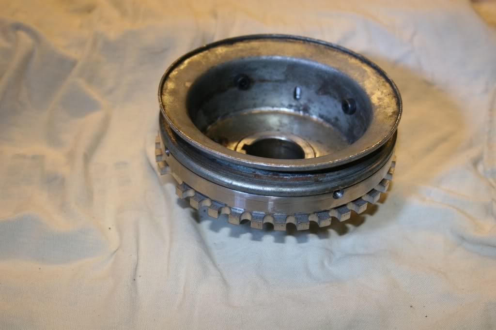 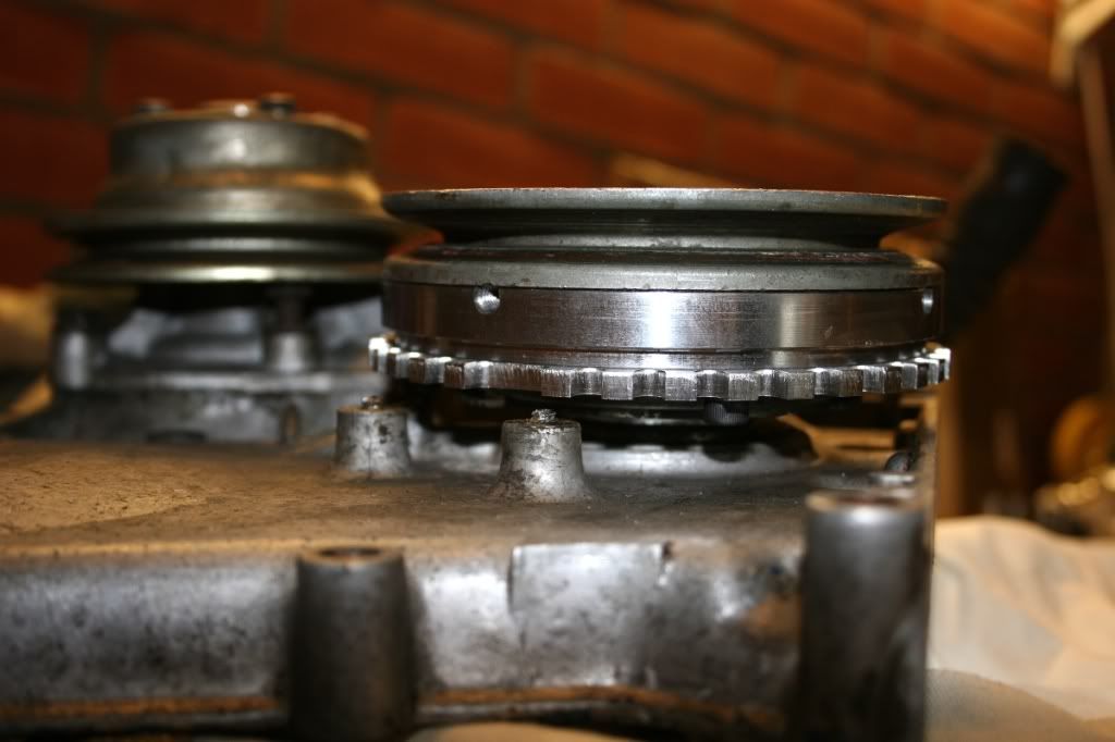 As can be seen the pulley has had an adaptor machined to sit just behind the belt channel to present a flat face for the trigger wheel to sit on. The other shot shows the was the trigger wheel sits when the pulley sits in the fron cover. This is mocked up on the bench but it can be seen that the trigger wheel sits nice and close to the front cover. This advantageous as it means the VR sensor bracket can be simple and still provide lots support. The VR sensor has to sit 1mm from the trigger wheel to work efficiently so the support nees to be sturdy!!!! And with very little run out on the trigger wheel. The type of trigger wheel i am using is a 36-1 configuration. This means it has 36 minus 1 teeth. The angle between teeth then is 10 degrees, which is a fine enough angle to allow batch injection and batch ignition. To have sequential of either will require a second trigger input. The trigger wheel supplies the ECU with two lots of information. As long as i have told the software code that the trigger wheel is a 36-1 it can then work out engine speed (RPM) and when No1 piston goes through TDC. It knows No1 TDC because i will have told the code the angle between the missing tooth and TDC. The VR (Varaible Reluctance) sensor is merely a small coil with many many turns of wire with a core like an electro magnet. As each tooth passes the sensor the magnetic properties are affected which causes a small ac current to be generated. The ECU takes this straveller ac signal turns into a nice clean square signal which it can then read i.e. looking for the missing pulse. For an engine to run the ECU requires only one more piece of information and that is engine load. Most times that is provided by a Manifold Absolute Pressure sensor, but running individual throttle butterflies like in twin webers means i have to use a Throttle Position Switch. The TPS is very much like a variable resistor and thus the ECU will know what position the throttle butterflies are in. The ECU can then look up on a table and see how much fuel or what ignition advance to set. These tables are what get filled in when a car gets 'Mapped' on a rolling road. For fine tuning the ECU also likes to know coolent temperature and inlet air temperature. With these four varaibles it is possible to tune the fuel or ignition table to produce very good results. In theory. ;D |
| |
|
|
|
|
|
Jun 10, 2015 16:25:35 GMT
|
|
Maurice,
Yes a head, an inlet and exhaust to go on my 1730 which i am building.
Nev
|
| |
|
|
|
|
|
|
|
Jun 10, 2015 16:25:56 GMT
|
|
|
| |
|
|
|
|
|
Jun 10, 2015 16:26:18 GMT
|
|
Front Pulley,
After spending a day pondering and trying it out i have sent the front pulley back to the machine shop. My father had explained to them exactly what was needed but they have not done what is needed. The main problem is the toothed wheel has no central register so can float about. This makes adjustment a nightmare as the teeth need to have less than 0.5mm run out whilst rotating. Also the conversion piece is fairly heavy and i am not sure iof the pulley will take the weight with out flying apart.
So, almost back to square one.
However, i did find an adjustable cam wheel in my spares dept.!!!!! Not sure where i got it from but it did not fit. The cam location/thrust retainer is now being counter sunk so i can fit counter sunk socket head screws instead of the current bolts. The wheel will then have clearence.
This should make cam timing a little easier. I have noticed another members engine has an access panel on his front cover so i presume he has done the same.......
Cheers
Nev
|
| |
|
|
|
|
|
Jun 10, 2015 16:26:55 GMT
|
|
Nicholas,
Some good points. He he trigger wheel in Ally would be funny!!!!!!
I am not using the EDIS module, i did with the V8 but i have decided to control the coild directly from the MS.
You are correct in that the sensor can be further away from trigger wheel, up to 5mm, but i do not want to find i am losing Tach Sync at 9000rpm.
I am not sure what the pulley is going to be made out of now but my/dads/machinists original idea of making a new boss with the toothed wheel and the belt pulley then added so that the strength is in the boss - if you see what i mean - i hope will now be used.
Cheers
Nev
|
| |
|
|
|
|
|
Jun 10, 2015 16:27:29 GMT
|
|
James,
I had not thought about having the pulley in a smaller diameter, i will discuss that with my father tomorrow.
As far as metalwork being easy - all i know is that a good bloke with a good set of machines seems to be able to make anything. Hard thing is paying for it and making sure they know what you want! Drilling holes is about my limit of 'pecision' metalwork..... ;D
Cheers
Nev
|
| |
|
|
|
|
|
Jun 10, 2015 16:30:09 GMT
|
I managed to get back into the garage now that Christmas has passed and carry on with the Tiger engine. Just before Christmas i had found an adjustable cam wheel, but to fit it i needed to counter sink the mounting bolts for the cam retaining plate like this: 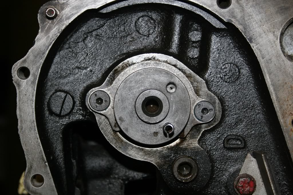 With that done the adjustable cam wheel fits a treat like this: 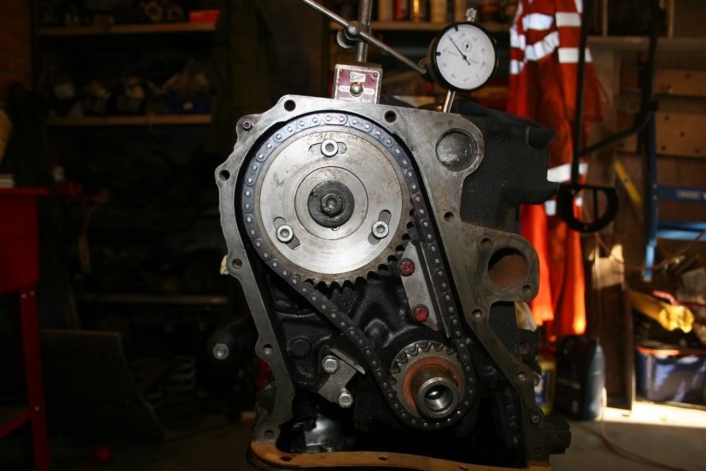 Then i could time the cam in. I first off timed the cam for equal lift at TDC with the head off, in hindsight it would have been easier just to go straight to when the head is on. I also timed it in with out setting the tappet clearence either so had to do it all again. I had a hang over. Eventually, after much mucking around with swapping my dial gauge between inlet and exhaust valves i managed to get the cam time in with equal lift on both valves at TDC. The inlet valve is open by 0.05mm more but that should help matters slightly. If i am feeling brave i may try and create an access port in the timing cover so that i can change the cam when the car is on the rolling road and maybe try a couple of degrees advance and see what it does. 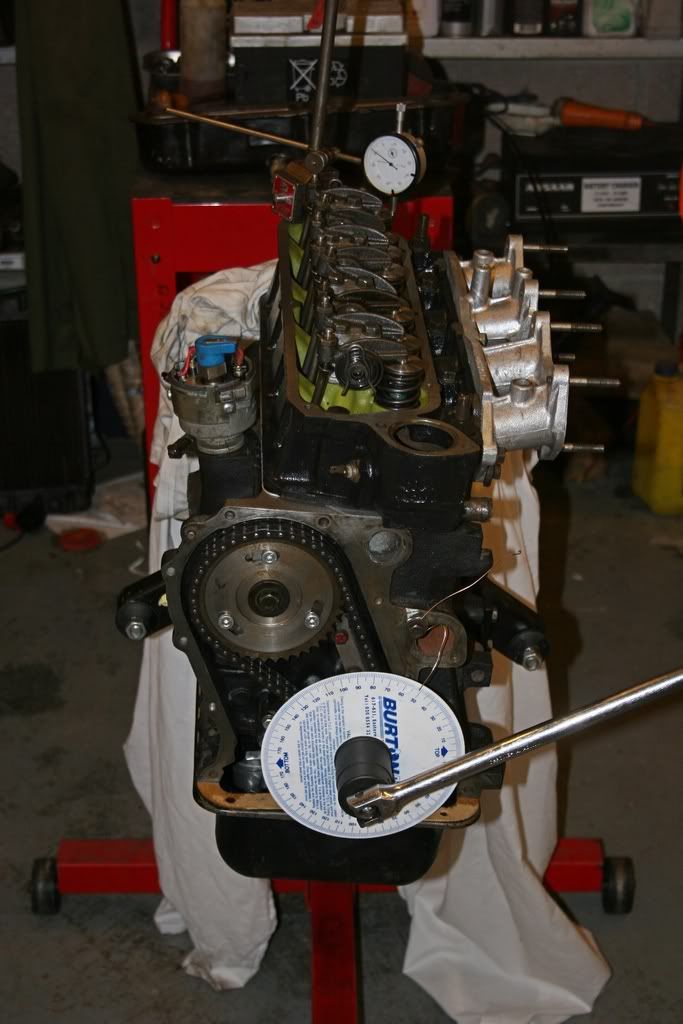 I am still awaiting the front pulley so until that arrives the engine will not progress much. I need to modify the exhaust manifold join to the exhaust as they are different sizes and if fitted as is would blow a bit. Also i have got to bleed the brakes and plumb in the main battery cable. After that its fit the engine and fire it up............... Nev |
| |
|
|
|
|
|
Jun 10, 2015 16:32:03 GMT
|
I finally got the front pulley back from the machine shop Saturday morning. He had decided that to fit the brief we had given him he would make it from one piece of metal, then add the toothed wheel like so: 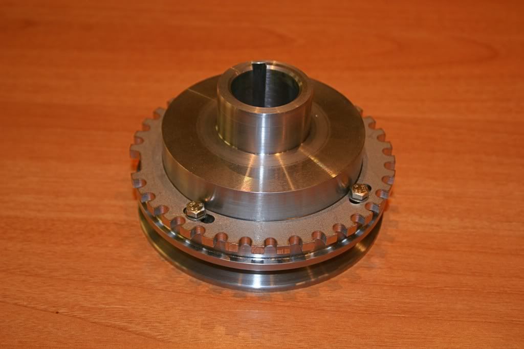 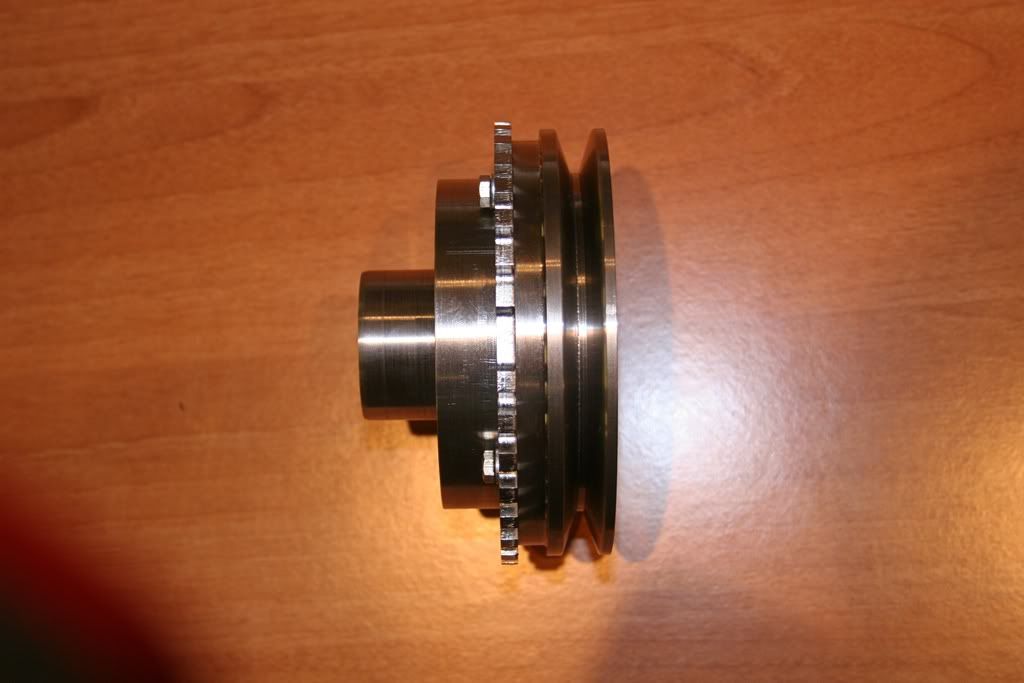 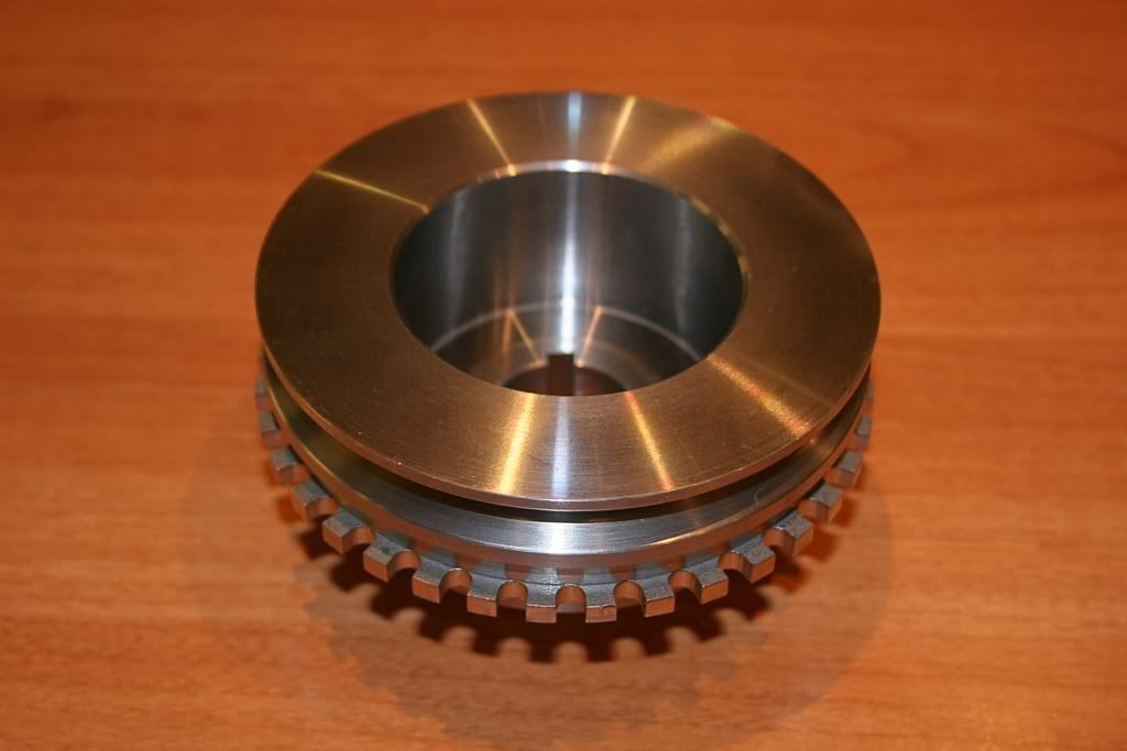 I have trial fitted it to the engine and fits very well with clearance where needed. Although machined from one piece its not overly heavy. I shall now fit a new front crank seal and then fit the pulley, alternator and a new belt. I can then make up a bracket for the VR sensor and once that is done i can fit the engine! Not much to hold it up now as the only other thing i need to purchase is a clutch plate and i can get it running. With luck and not tto much working away it should be going sometime in March!!! |
| |
|
|
|
|
|
Jun 10, 2015 16:32:38 GMT
|
|
As far as i am aware there are no 'Off the Shelf' adjustable cam drives for the Avenger engine.
You can see from one of the photos that the roll pin is still present and thus provides an element of location and drive between the pulley and the cam shaft. However, i don't believe the roll pin is present on a standard engine for anything other than location for timing purposes and all the drive is from the pulley being brought up tight by the bolt. Much like most modern engines rely on the cam sproket/cam interface for drive purposes.
I am also confident that the three bolts will provide enough clamp for there to be no relative slip between the three bits of the sproket and thus no slip in timing. Will we see when it gets a bit messy on the track and i start using all the revs i can...............
Just spent some time researching which software to use on my microMS, i don't think i shall be able to use Extra which is a bit of a let down due to insufficient I/O but maybe a bit more thinking and it will all come clear.
|
| |
|
|
|
|
|
Jun 10, 2015 16:33:22 GMT
|
|
Prior to finding this adjustable socket, i would set the cam so the valves were at equal lift at TDC and then drill both the sprocket and the cam and then fit a dowel at that position.
Not adjustable but it was good enough for i what i wanted and understood!
|
| |
|
|
|
|
|
Jun 10, 2015 16:35:27 GMT
|
Feb 2009: As i was not going to Bath & West Showground it meant i had a bit of spare time so: Here is the VR sensor now mounted next to the toothed wheel, the positioning of the VR sensor is almost not an issue relative to the missing tooth and any of the other teeth in fact. The software i will first use allows coarse and fine adjustment in software. So i can tell the software that the VR sensor is X teeth behind the missing tooth and then x degrees around the centre of the tooth i am using so it leaves less trouble mechanicaly as it were! 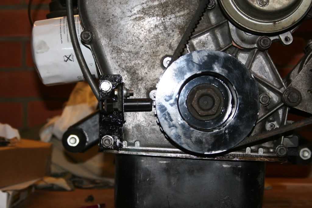 Here is an overall shot of the front of the engine on the bench: 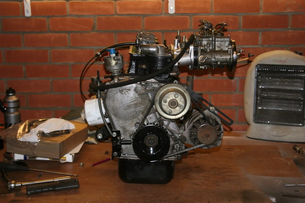 The VR sensor is well out of the way of anything moving and gives easy access too. And then i managed to get it in the car: 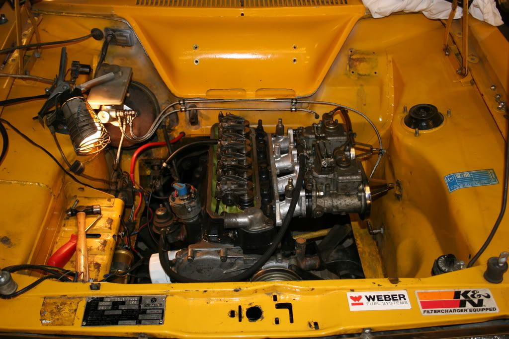 I got on well and it now has the gearbox mounted and the prop shaft. The rest of the afternoon was spent modifying the exhaust manifold as it never really fitted the rest of the exhaust, i also have made provision to fit the O2 sensor as well. The O2 sensor is run by an Inovate LC-1, very good, well made and good value but they are designed to sit on the outside of the car. I mounted it originaly in the cab of the Tomcat but that meant a large hole to get the sensor through or a massive hole to get the controller through! I will again mount it inside on the Tiger but its a real pain trying to get a grommet that will go over the sensor and then seal the cable without it looking like a bodge!!!! Some thought required. Brake bleeding tomorrow as i can borrow my dad to help! Another day/2 days or combination of hours will see it running. |
| |
|
|
|
|
|
Jun 10, 2015 16:36:34 GMT
|
|
I will have a look in the morning. The manifold has long secondary pipes and so the boss has been welded onto the first bit of single pipe and that is as far back as the gear stick hole in the transmission tunnel. I know i can get a big stretchy grommet from places like Demon Tweeks but i suspect i will come up with a solution eventually!
I can run twin o2 sensors with different software so when i fuel inject i shall probably do that. Where it is is adequate to log AFR when on carbs and experience shows it will log it accurately enough. On a rolling road they only stick their sensor up the end of the exhaust pipe. On the Bowler it was even further back as the two banks didi not meet until just before the rear axle!!
Brakes proved to be very difficult to bleed this morning. So we took the new old stock master cylinder off to check it out and we found enough corrossion in the bore to hide a landrover. Great!
However, i may get it started tommorrow.
The software has the option of 'Self Tuning' where it uses the O2 sensor in a feed back loop to keep the fuelling the same as a 12x12 look up AFR table. EGO correction.
This can also be used whilst the car is in normal running with an amount of EGO correction always working to keep the engine locked to certain AFR's. vwry useful for emmissions.
However, i have never used the EGO correction facility as i have tuned it to where i want it and then let it run like that. In my experience the engine is doing so little mileage but running flat out and changing speeds so quickly that the EGO correction does not have time to average out the readings it needs to give good feedback. I am sure they could be advantages of using EGO correction on a competition engine - its just that i have not got round to working it through!!!!
|
| |
|
|
|
|


