|
|
|
Jun 10, 2015 16:36:56 GMT
|
|
Remember that virtually all modern o2 sensors are 4/5 wire devices with a heater which means they are not relient on the exhaust gas temperature for operation.
My Bosch sensor as used in many VAG vehicles heats up in approx 30 seconds and is then giving accurate AFR readings, very useful when tuning cold start/warm up enrichment.
Also modern o2 sensors are wideband giving a linear voltage output (from the controller) directly related to the AFR rather than the old fashioned 2 wire narrow band sensors which only give indication of the stiochromatic (spelling?) ratio of 14.7:1 AFR.
I always ran with my o2 sensor fitted to the V8 even though there was no EGO correction so that i could log transients and see what was going on if i thought i had a problem. Biggest hassle with that was trying to keep the lap top from flying around.................
|
| |
|
|
|
|
|
|
|
Jun 10, 2015 16:37:20 GMT
|
Managed to get the engine running this afternoon, albeit very reluctantly! I was having a bit of a game trying to turn it over and check the timing. Any way its running with about 40 degrees all in at the moment and it starts so i guess that is a bonus. I have also convinced myself there is a knocking noise from the front of the engine! Paranoid. My father is over on Friday so he can have a listen. One problem is the head gasket is leaking at the front of the engine, i noticed this before starting the engine. Its leaking from right at the front next to the thermostat housing for some reason. No water in the cylinders but i am not sure about water and oil mixing though. The head was torqued down correctly but its doing its best to dump water out the front. New head gasket is on its way so will have to have the head off Friday afternoon to check and see whats going on. I spoke to another club member and he had also had exactly the same problem too  |
| |
|
|
|
|
|
Jun 10, 2015 16:37:41 GMT
|
|
Head Gasket problem solved.
It helps if its put on the right way up.......................
Engine started and run for 30 mins at 2000rpm. Now to change oil, sort out some little niggles and get it MOT'd as long as i get time!
|
| |
|
|
|
|
|
Jun 10, 2015 16:39:56 GMT
|
So i spent this morning playing with the throttle cable problem. This is the new cable end: 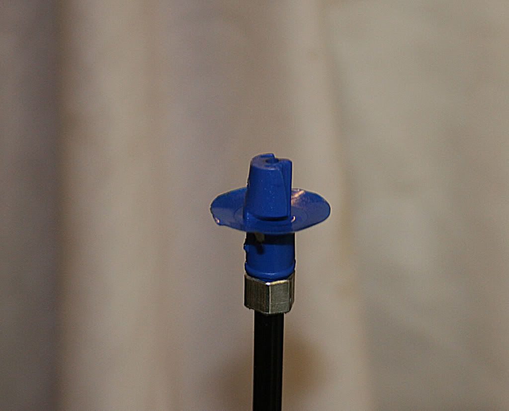 As it can be seen the end has a plastic guide that allows the inner wire to stay clear of any metal. I modified the bulkhead so there was a big slot and then made up a piece of shaped aluminium to hold the cables and allow some movement to get them in the best position before securing : 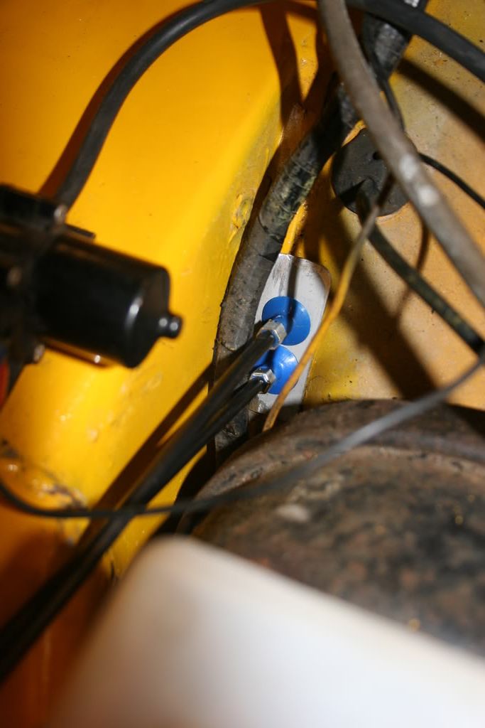 The pedal movement is now really smooth. Very few things to finish before an MOT but ran into some problems today. First the strut brace hit the M/C resevior and caused it to leak which was solved by removing some of the strut brace! I also noticed a very small water weep at the back of the block which i can't trace. New headgasket fitted right way up and its still leaking at the front, block and head are true - very puzzled. And the cam is very noisy mechanicaly. After a good long think i suspect one of the cam followers is a bit sticky. It should calm down after a while......... 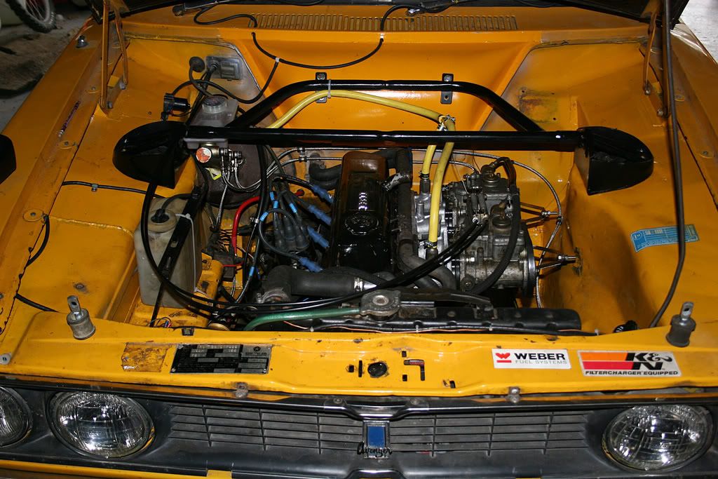 |
| |
|
|
|
|
|
Jun 10, 2015 16:41:12 GMT
|
|
Well that gets us to the end of Feb in 2009.
This going to be a pain alright, a labour transferring the text and then re-linking the photos...........
More instalments tomorrow.
|
| |
Last Edit: Jun 10, 2015 16:42:55 GMT by nevtiger
|
|
luckygti
Posted a lot
   I need to try harder!
Posts: 4,912
|
|
Jun 10, 2015 20:13:19 GMT
|
|
Looks great though, looking forward to the updates as they come.
|
| |
|
|
|
|
|
Jun 11, 2015 11:16:14 GMT
|
|
So i managed to get us through to Feb 2009. I had owned the car for a fair few years prior to then and it had been a road car but still doing the odd 12 car and auto test, so lets see where we are going next:
|
| |
|
|
|
|
|
Jun 11, 2015 11:16:34 GMT
|
|
Finally managed to get some time this afternoon and finished off the bits and bobs for the MOT.
It passed!! ;D ;D ;D
However, they at first could not find the car on the system so used the V5, no drama. But then the MOT tester wanted to fail the number plates for being the wrong type i.e white on black as the system said 16/01/73 for the car but its a 1972 car as its build date was in 1972. Anyway he did not seem to mind really so its all good.
Rolling road once i have done a few miles to run it in and then on with the MicroSquirt fitment!
Phew!
|
| |
|
|
|
|
|
Jun 11, 2015 11:17:12 GMT
|
|
Rolling Road booked for the 27th March at Slark Race Engines in Amesbury.
Last time there it made 100hp at the wheels using a Grp A cam, Grp 1 head, 32mm chokes and 35 degrees advance.
This time it will use a Grp 2 cam, much modified head and i will try and get him to use more than 35 degrees advance ( i think i can go to 43 with out to much drama) as he had never needed to before as mine was his first Avenger!
I hate to guess what it will be but more than 100 will be nice.
It will also allow me to plot a base ignition curve and compare to my computer simulation generated curves ready for when i switch over to the MicroSquirt.
|
| |
|
|
|
|
|
Jun 11, 2015 11:18:25 GMT
|
Rolling Road today! It took ages befoe they could do my car as a Mini Cooper S they started yesterday was playing up, so i did not get on until 12:00 after being booked for 09:30. First run was good and produced a nice curve. Checked the ignition and it was 50 degrees all in. Neil was very worried about this and would not believe me that it needed lots of advance so after he knocked it back to 30 degrees and then did another 4 pulls each with more advance he finally believed me!!! Settled on 44 degrees and need to change the main jets to a richer version as the top end was leaning out to 14:1 and the air corrector was at the bottom limit. So was there an improvement? Compared to the old engine i now have a little more top end power but check the curves. The thick black lines are todays best and the grey lines are the previous engines best. Not quite as rev happy and not such a broad rev range but huge amount more midrange all the way through! Torque is massively better. The figures quoted on this dyno are very conservative and as a rule the flywheel figure will equal every one elses wheel figure apparently! A very good 5 port 1300 Full race/Hill Climb Mini engine makes the same as this engine so thats a good indicator of what its doing. Plus today was much lower pressure than the last test. It will be nice to see how it performs against Phils Avenger race car in france - Pre-emptive excuse...........his is much lighter than my Tiger!!!!!!!!!!!!!!! It did leak a huge pool of oil at one point but we could not find where it was coming from -cough-  New spec is Group 2 Cam, Flat top pistons +20, SRE Head with 1.7 inlets, 32mm chokes on 40's, 10.5:1 CR and 44 degrees all in. That compared to Group A cam, 11:1 CR, 35 Degrees and a Group 2 factory head. The disadvantage of the Grp 2 cam is it will not pull anything under 3000rpm. Next step is to finish installing the Microsquirt of which i am half way through doing the loom and then get it on the rollers again. I now cant wait to build my Petteri headed 1740! 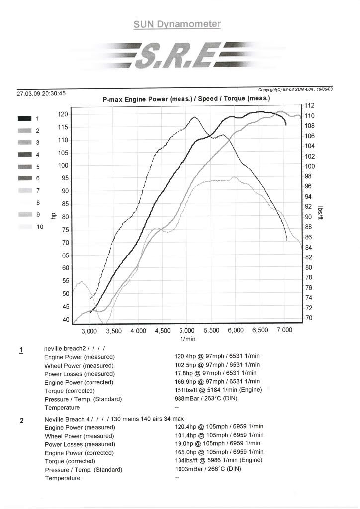 |
| |
|
|
|
|
|
|
|
Jun 11, 2015 11:19:05 GMT
|
ust thought i would add this of the car at the rolling road. I have a video of it as well but i don't know how to do that! 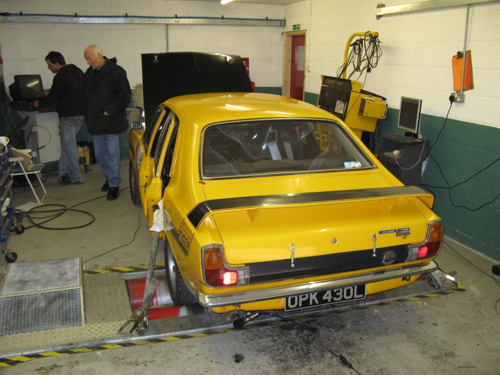 |
| |
|
|
|
|
|
Jun 11, 2015 11:21:25 GMT
|
I spent today getting the new ECU loom extended where necessary and adding terminals and plugs to the end. Here it is on the bench looking like a squirels nest: 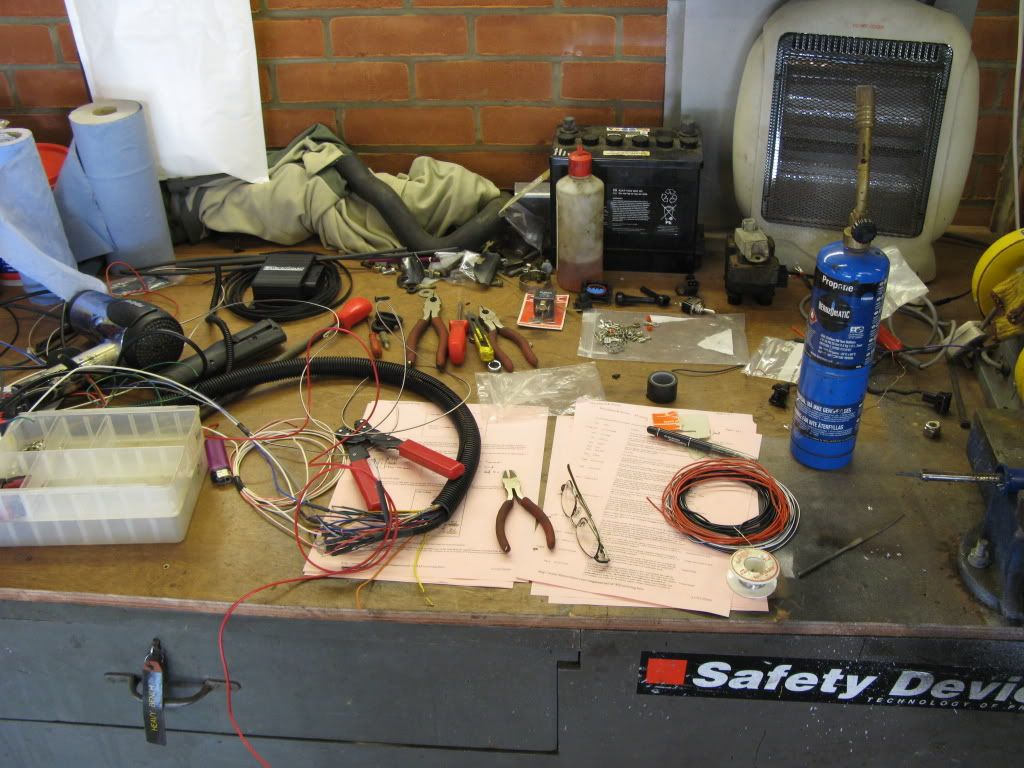 As i am only doing ignition to start with i only needed to wire up the VR sensor, Throttle Pot and Coil Pack. The Coil Pack uses a Ford moulding so i took it to pieces and put new Gold terminals in, the VR sensor uses a 2 way Junior Timer and the TP a 3 way JT. Both of these i have fitted new including Gold terminals. Loom was in and out of the car a few times before the engine bay lengths were near right. Got it to this point and looking much tidier on the engine end of the loom. 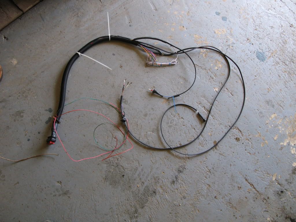 I also started to fit the LC-1 Wideband Controller which controls the Lambda sensor and gives the ECU a 0-5V linear signal for AFR. Although i will not be using this facility to control anything as yet its nice to have and means i can log what the engine is doing with carbs! Got to get this lot in the cab. As its American its designed to sit on the outside of the cabin attched to the 'frame'. It looks dirty because it was last used in my Bowler. 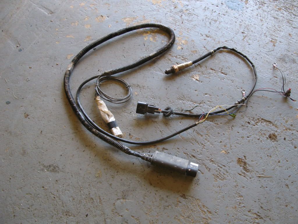 When the injection system goes on i shall change the wiring slightly as i have fed via fuses the ECU, Coil pack and Lambda sensor whereas when i move to injection i will need to change the wiring so thatthe injecters and the coil are fed from a relay and a further relay for the fuel pump. But for now a switch controls the feed and a lamp reminds me its on! As it is now ready for the ECU to be mounted, LC-1 to connect into the ECU and all the other connections necessary! 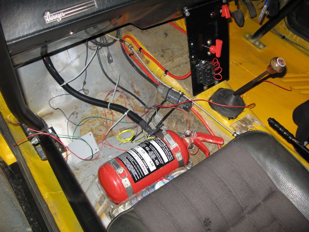 |
| |
|
|
|
|
|
Jun 11, 2015 11:22:39 GMT
|
|
Here is a video of the car on the Rollers:
|
| |
|
|
|
|
|
Jun 11, 2015 11:24:21 GMT
|
I managed to get the wiring all complete and bar a little tidying it looks like this: 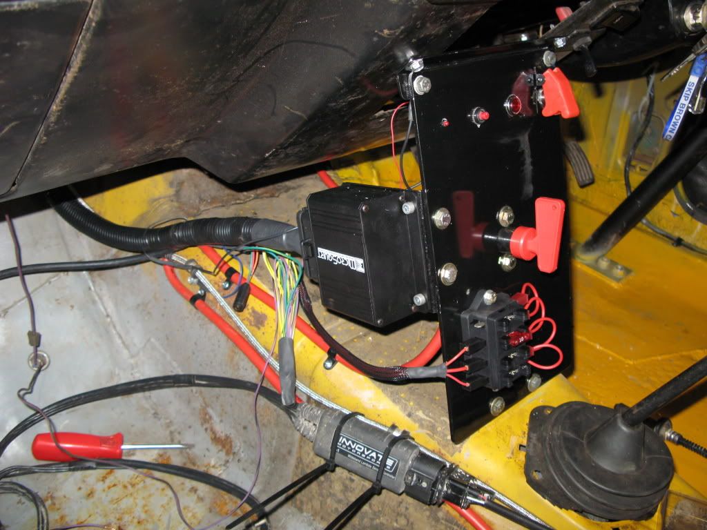 The o2 sensor can just be seen in the drivers footwell. I powered up the LC-1 first and then calibrated the o2 sensor for free air - hence why its in the drivers footwell! Next i powered up the coil pack - 12v present and correct. I then powered up the ECU and tried to establish coms. As my lap top only has USB it means i have to use a Serial USB converter. Every time i start the lap top the virtual port moves so i had a bit of chase to lock the port down to tell the Tuning software where to go!! It still diod not work thoughw hich left me baffled until i realised that serial coms are 9600 baud but the USB and the ECU wanted much higher so i reset the port speed to 115k and connection was established. After setting up the 'Project' in the tuning software - Tuner Studio for Megasquirt - i calibrated the TPS as its an easy thing to do and gives cofidence. This is achieved by a calibration window where the ECU gets an 'ADC count' - basically a voltage reading for closed and then one for wide open. It then calls these 0% and 100% and works it out from there. Next move was to start the engine and see if the ECU could track the rpm. This would prove the VR sensor and trigger wheel arrangement. Unfortunately, it did not work very well as i think i have not set the parameters correctly in the ECU. I had to stop as i needed to do some weeding! A bit of research is required as i need to be sure of how to se the ignition parameters for reading the trigger wheel before trying again one evening. I was very pleased that it worked as well as it did as i only had an hour to play with the lap top before gardening duties overtook fun.  And a shot of my Lotus: 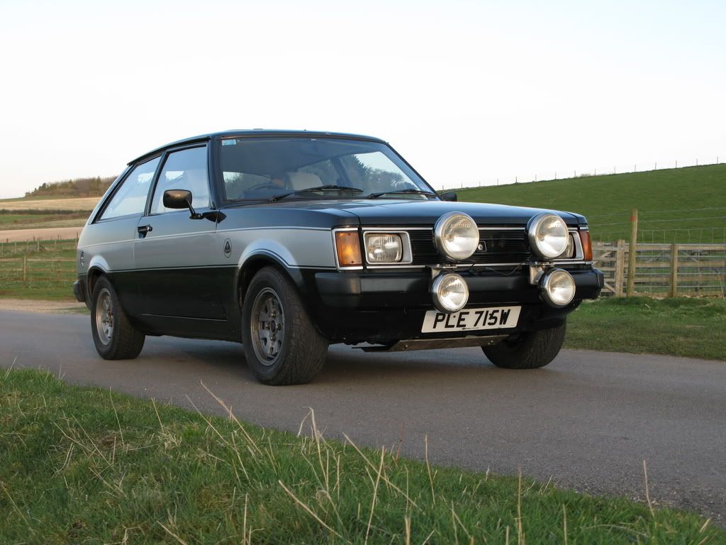 |
| |
|
|
|
|
|
Jun 11, 2015 11:25:09 GMT
|
|
James,
The pc side of things sounds more scary than it really is. It is normally Plug and Play but I am using my company laptop that does not like 'Test Software' being added to it so needs an element of circumnavigation! If i had my own lap top or pc in the garage then it would be much simpler - honest!
Yes the terminals are a mix of crimped and crimped & soldered depending on application and material used. Also lots of heatshrink used. I have used 'orinary' 3:1 adhesive lined stuff as i thought the DR - as used on F1 looms - stuff was way over the top cost wise. I can't remember the exact cost but an indication is the main switch i used for the feed is in the region of £5 but the next one up was £25 and used in Classic 70/80's F1 cars. Adrian has it all as he does Looms for all sorts and lets me have the parts at discount.
Gardening had to be done else i would not be allowed to play on the car!!!!!
|
| |
|
|
|
|
|
Jun 11, 2015 11:27:06 GMT
|
|
I won't have the engine running on injection by May as i still need to get Throttle Bodies, Injecters, fuel rail, pressure regulator, fuel lines, pump, filter and either a new tank or second tank/swirl pot/ external sump, air temp sensor, water temp sensor. The latter two will installed and wired up in stage 2 and finally injection in stage 3.
I keep an eye out on ebay for a set of Jenveys or equivilent but have not discounted motorcycle injection bodies. The only problem with the MC bodies is making them fit. Not beyond my capabilities but time consuming to get right with the correct spacing etc.
I think i have worked out the no rpm situation and will try it later once i have stripped the cam covers off the Lotus....
|
| |
|
|
|
|
|
Jun 11, 2015 11:27:19 GMT
|
|
had another go at getting some rpm reading last night and failed again.
I used two dofferent sensors and wired them both ways still with no luck.
I have put the trigger wheel on (with out thinking)so that the missing tooth corresponds with TDC for 2 and 3 which may be upsetting the software when i dial in the figures for where the missing tooth is. It maybe tring to sync on a tooth that is not there. i shall move it round 90 degrees next chance i get and try again.
I checked all my connections, belled it all out and it all appears good so i must have set the software incorrectly and/or the trigger wheel is causing me this problem. Frustrating.
Time will tell.
|
| |
|
|
|
|
|
Jun 11, 2015 11:27:41 GMT
|
|
RPM reading all fine.
I had the setting for the pick up incorrect. Essentially i was telling the ECU to use the wheel back to front. It works with a good steady rpm reading. All the other settings are now correct.
I then started to look at tuning the spark map for the engine and filling in the basic settings etc. As i am not using a MAP sensor it means i am using the RPM and the Throttle Position to tell the ecu where to look at on the Ignition table, thus there are a number of settings with in the tuning software that can be changed on drop down menus. I am also using a new Beta version of a tuning software - which in hindsight was a mistake - as it does things in a slightly easier way than the older but reliable software i have been using (which requires ini files to be modified to get Alpha-N). It seems the new Beta i am using would not set my ecu into Pure Alpha-N mode and the ecu was still looking for the MAP sensor. Whilst trying to work this out and changing the settings i switched the master switch off however i had a battery charger connected upstream of the switch. The charger then had no load so delivered a high ac voltage which toasted the ecu......................
My fault as i was pre-occupied by the settings on my ecu.
When i get the ecu back and they may take a while as the supplier is always busy and i am not a paying cutomer, i shall go back to the old software and it should be a quick job just to get the car running on the mapped ignition now as its all ready to be plugged in.
it is doubtful whether i will have it installed for France now though.
|
| |
|
|
|
|
|
Jun 11, 2015 11:31:26 GMT
|
So with the ECU at the supplier being investigated i decided to set up my front suspension. I had a set of rose jointed bottom arms and rose jointed brake reaction arm mounts on the shelf which i had never used but had been lying around for a very long time so i thought i might fit them on. The arms did not have rose joints with them but i bought some Ultra High Performance joints and spacers from McGill Motorsports who appear to be the cheapest of the bunch. Although the arms are not adjustable on the car i am thinking that once at a position i like i wont need to change the postion often if at all. 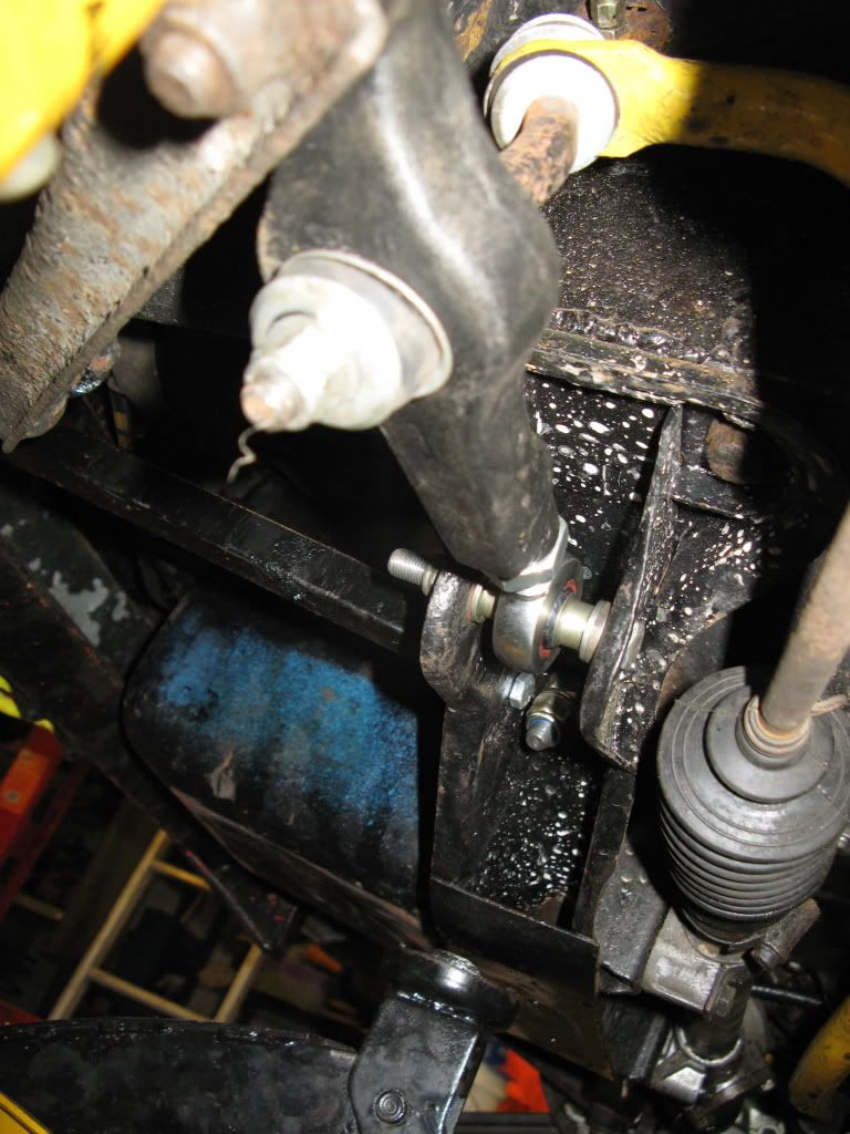 Again the front mount is not adjustable on the car but i can be adjusted when and if necessary 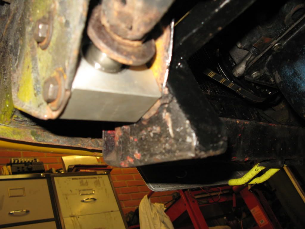 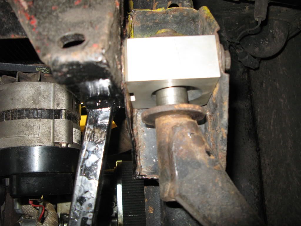 These front mounts act in the same way as the original does but using a rose joint instead of a rubber bush. The original arm can be used and i believe they were used as a solution on the works car. Some people have expressed concern in the past about this method of mounting the brake reaction bar as the rose joint is not working in the plane it was designed for. However, my car is for the sprint/hillclimb track so will not see the forest so i believe the loadings and certainly the shock loadings will be less. I also installed with the big original washers so if the rose joint does fail then the movement will be retsricted. The Static Negative Camber now sites at 2.5 degrees 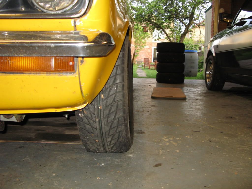 Castor i have not measured directly but the strut angle is the same as before at 6 degrees. I had been using old Avenger brake reaction arms which add alot of castor and it felt fine so have just set it up to the same strut angle. I also checked that my biggest wheel/tyre combe still cleared the front valence as well. Once the camber was set the tracking needed to be aligned 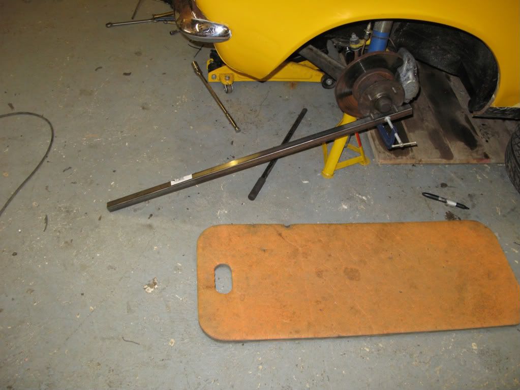 I clamped some square stock to the hub on both sides and adjusted untill the arms were parallel. I will check this at they local tyre shop this weekend and see how close i was. I have though of a way of measuring even more accurately than my tape measure laid across the bars, but it needs a bit more fabrication. I had a very brief look to see if i could tell whether the steering arm and tca are parallel, hence why i had been wondering on another thread whether there was an excepted mod to be made that had been proven in the works times. 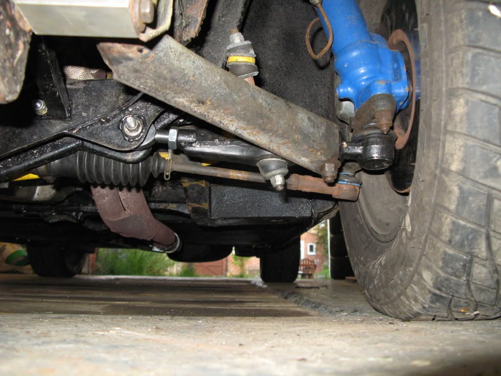 Its hard to tell just looking and i have not yet worked out an accurate way of measuring it as the pivot points are hard to gauge accurately. I also fitted the missing door bar. I just need to road test it now, change the oil, fit the track tyres and its ready for France. |
| |
|
|
|
|
|
Jun 11, 2015 11:33:15 GMT
|
|
The joint is in the plane of the bore so is essentially a side thrust for it, hence the element of caution.
I did think of making a solid bar at the correct distantance to go between my two 'hub bars' but if i change camber/ride height that distance would change.
I think with an accurate measurement in my garage i wont need to have it chaecked else where.
|
| |
|
|
|
|


