|
|
|
Mar 17, 2011 12:04:54 GMT
|
Yours is different to mine... But its pretty simple. (theoretically) If you have a multimeter... Also: www.mopedarmy.com/wiki/Puch_wiringIIRC the yellow is the main lighting coil power.... White is rear light. So when you switch the lights on, the connector inside should join the yellow and white together..... Id Get a pic of mine but its an early one so only has three wires... 4 now as its got a cutout swtich.... |
| |
|
|
|
|
|
|
|
Mar 17, 2011 13:15:06 GMT
|
|
Ah of course front and rear lights... So they're probably right then. The main yellow is one of the ones I'm unsure of.. I need to get it running I guess and the. See what's working or not. It's just a bit annoying not having a constant power source - I'm not the hottest when it comes to the average 12v car system (see my capri build thread in my sig - got there with electrics in the end!) but this 6v malarky that only powers stuff when it's running!! I suppose I could check for a spark without the switch hooked up properly?.... Or could I? Does there have to be a full circuit or something? I'm sure I read that these won't run if the horn is disconnected? Probably internet balls!
|
| |
|
|
|
|
|
Mar 17, 2011 13:18:49 GMT
|
|
Just checked your link and yeah it seems everything has to be connected for there to be a spark...
|
| |
|
|
|
|
|
Mar 17, 2011 13:28:26 GMT
|
Ummm iirc. To get a spark you don't need any of it connected (i think) As it just generates a voltage from the mag to the coil (yours have an external coil?) The points close, It earths, Ht provideds spark to the plug. To stop the bike all they did was add a wire from the LT side of the coil (condeser/ points/ white wire on the coil) to a switch, When you press that switch it just earths it to prevent the HT winding from building up any power. So theoretically you could hack all the wiring out (appart from the wire to the coil) and it would run. (i think) lol Thats from my little play with mine yesterday....  That said you'd have to rely on the decomp valve to stop it.... And the switch has to be connected to the handlebars for that to work too (so it can get earth) |
| |
Last Edit: Mar 17, 2011 13:29:49 GMT by retrowagen1234
|
|
|
|
|
Mar 17, 2011 13:55:54 GMT
|
|
Hmmm. Ive wired a black wire into a copper run in the switch body that when the killswitch is pressed must earth it... But the main YELLOW wire is the one I've wired into the killswitch... Would that be right do you think?
I should really read more thoroughly! So the yellow is the main power to the lights... Shame there are so many variations of switches and wire colours through the production of these bad boys.
|
| |
|
|
|
|
|
Mar 17, 2011 15:36:26 GMT
|
It runs without any of the wires connected. Easiest way to troubleshoot wiring issues is just disconnect everything.  |
| |
1985 MK2 Golf
|
|
|
|
|
Mar 17, 2011 15:44:16 GMT
|
|
Well on mine the yellow doenst go into the kill switch. All that would do would be earth the lighting coil (imho)
You need to earth the black cable (i think) to kill it. So that should be in the kill switch hole.
|
| |
|
|
|
|
|
Mar 17, 2011 15:55:23 GMT
|
Cool, well I've got the black cable connected to what seems to be a common earth copper strip in the switch? should I have the yellow in there and the black at the other end to get knocked by the kill switch? Which I'm presuming is the one on the side of the switch?!  Even on a tiny little simply wired moped - electrics still do my head in! |
| |
|
|
|
|
|
Mar 17, 2011 16:11:15 GMT
|
|
yeah yellow wants to be on that common strip, Black needs to go to the pin that gets earthed when you push the kill button, What does the back of the switch top look like? (the bit with the buttons on?)
My kill switch is just a plunger on the end of it...
TBH i like this little discussion as its helping me get my brain round my bike... I keep on trying to concentrate and deciding to modify somthing else haha
|
| |
Last Edit: Mar 17, 2011 16:11:55 GMT by retrowagen1234
|
|
|
|
|
Mar 17, 2011 16:22:15 GMT
|
Just took a pic for you ;D 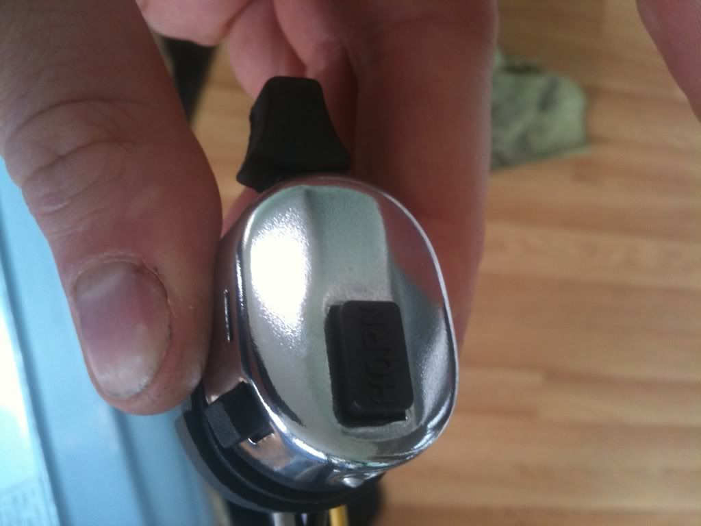 Horn is the top one, killswitch on the side So now mines like this - reckon it's right? 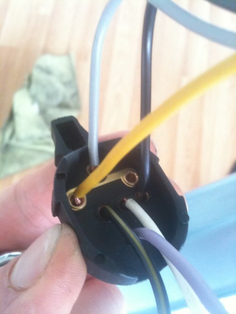 On another note I accidentally pulled the wire out the back light and don't get where it's supposed to go? There is no evidence!! |
| |
|
|
|
|
|
|
|
Mar 17, 2011 16:36:48 GMT
|
just had to quote these pics so i could compare them 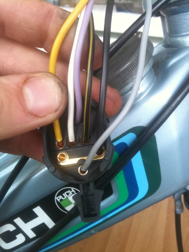 i think ( THINK) The black and the black and yellow stripe need to be swapped over. Then i think its the same as mine..... As for the rear light... Its just a single white wire to the tip of the bulb isnt it? The earth comes thru the body of the lamp into to the frame. As for testing it all. If you have a multimeter you can run one probe onto the yellow cable from the engine, And the other to ground (seat clamp for example), Kick it over / bump it down the road and it SHOULD produce a current.... Then you know you have power from it. Then its just a case of making that yellow wire send the power to different parts of the bike when you move the light switch/ press horn button...
|
| |
|
|
|
|
|
Mar 17, 2011 17:58:36 GMT
|
|
Ok so Ive swapped them over - it seems to make more sense if theres one live for all the ancilleries and one pickup.. we'll see soon eh?!
As for the back light, its a bit odd - there isnt a place on the back of the bulb/holder for the wire... it SEEMS the spring that holds the bulb steady and in place, doubles as a rubbish clamp for the wire :/ done that anyway and it seems to hold alright. I need to buy a number plate now before I fit the light along with bracket for the plate but I cant find my V5 - oops.
Ill find it soon I reckons.
Also done a bit of autosol polishing of the metal for the sake of it and popped my cable/loom tidy back on (although Ill have to take it of again to fit the back brake cable properly) but it makes me feel better about it to see it looking a bit tidier!
Thanks for helping with the leccys dude, hope my throttle loop gets here soon as I want to try and start it....
|
| |
|
|
|
|
|
Mar 17, 2011 18:26:40 GMT
|
Might have a bit of an update for the brake issue tonight too dude  Going to pop the back wheel off quick in a sec to check some other bits and ill post the results on my thread As for the wire.. Was it soldered? |
| |
|
|
|
|
|
Mar 17, 2011 19:37:31 GMT
|
Cool look forward to results I measured the back cable, the guy on eBay who sells puch gear said he has had the same problem with his and that no one lists a different length one! The wire on the light wasn't soldered - there is no evidence it was ever fitted! I presume it's ok as it is but I might flash some solder over it to be sure |
| |
|
|
G A R'goyle
Part of things
 Bad to the bones Senior citzien
Posts: 115
|
|
Mar 17, 2011 21:22:46 GMT
|
 No letters or numbers on the switch? On my maxi the electric is like this: Four cables from magneto Yellow - to 56 in switch Green - to brake light switch if there is one Grey . Taillight (early ones uses 58 in switch) Black - K in switch (some older peddlers don't have this) then 56 A and B are low and high beam White & White/yellow I use to connect high beam to center position on the lever H is horn brown The cables are connected to a screw plint in head light A short piece is jumped from the yellow to the + side of the horn I hope it helps you, my maxi is a Swedish market one 
|
| |
|
|
|
|
|
|
|
|
No letters or numbers on mine no :/ bit stupid really as it's significantly different to the standard switch I replaced, thanks for the help though - may come in useful if I get it running and nothings working!
|
| |
|
|
|
|
|
Mar 18, 2011 11:49:21 GMT
|
Well thanks is to retrowagons heads up I have good brakes 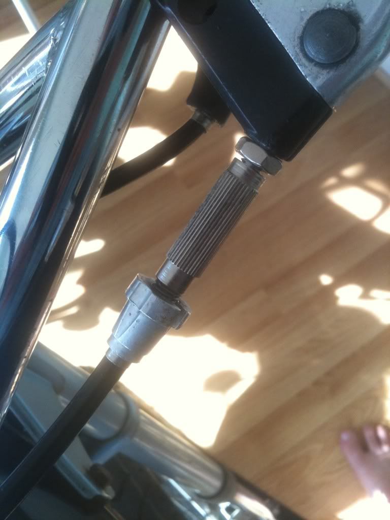 From my parts curse word BMX Much better: 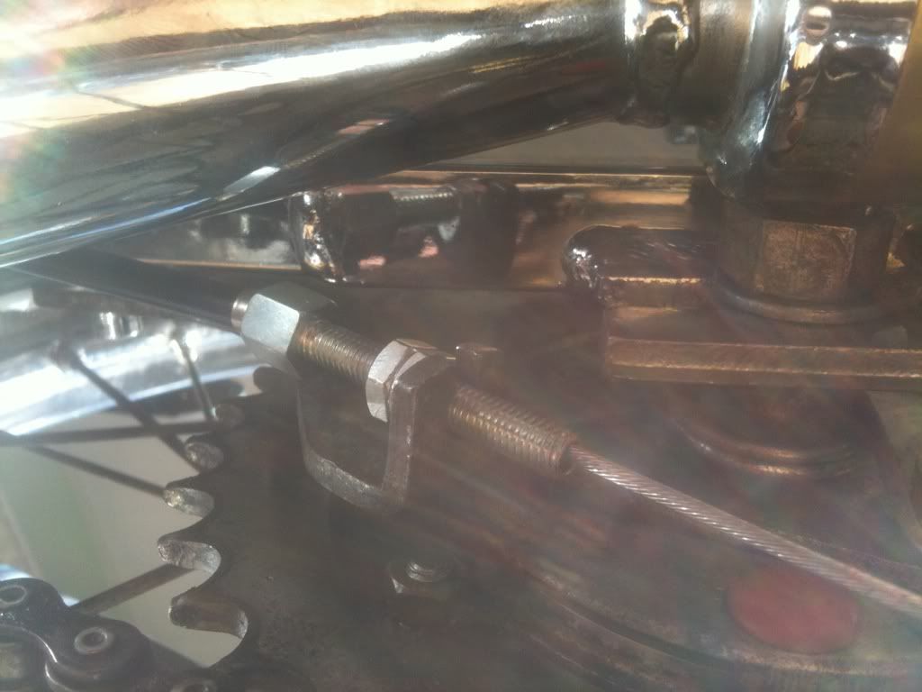 Cable and loom tidy replaced and cable route sorted: (ignore throttle cable dangling it's awaiting the infamous throttle loop) 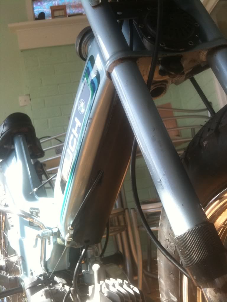 Tidied up the cables bar end with a few strategic cable ties too. The horn has two take offs, one is straight to the button on the switch, the other is broken - I'm presuming an earth wire bolted to the 'chassis' is all that's needed on there? 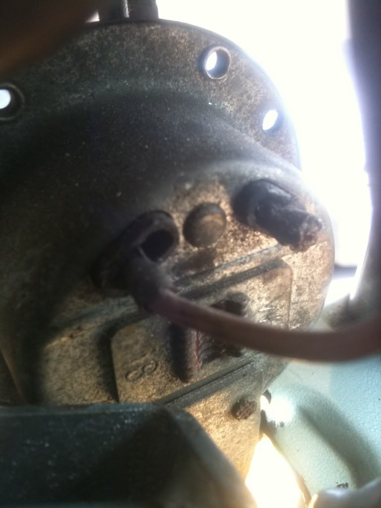 Not much left, the turning point will be this loop - I fear it's lost in the post though. |
| |
|
|
|
|
|
Mar 18, 2011 12:39:18 GMT
|
I (think) The horn should have a connection to the yellow wire somewhere there. Mine was broken off too. The horn has a constant voltage from the yellow cable. And the brown goes to the switch. You press the switch and it earths it creating a circuit... Doing good tho.. Nice to see your brakes are done too |
| |
|
|
|
|
|
Mar 18, 2011 13:36:55 GMT
|
So just a scotch lock or solder into the yellow wire then.. I'll whizz it off and see how damaged the terminal is. Can any Puchers confirm our ponderings with the horn wiring? |
| |
|
|
|
|
|
Mar 18, 2011 13:55:58 GMT
|
Well thats how mine is...And i read it on a post on moped army the other night while trying to figure it out myself... Then went and had a look at the ped and saw the remains of said wire hanging from the loom..... From looking at the wiring diagrams it seems they changed it alot depending on where it was sold, When and what spec the bike was...  |
| |
|
|
|
|


 Going to pop the back wheel off quick in a sec to check some other bits and ill post the results on my thread