|
|
|
|
|
You'd think this info would be easy to come by, but apparently not. The 5 wire style lock actuators for central locking, I want to wire one to actuate the passenger lock when the drivers lock is opened. The wiring according to Car Builder solutions: BROWN - Lock Input BLUE - Unlock Output WHITE - Unlock Input Black - Earth Green - Lock Output The brown and white are quite clear, supply momentary 12v to either lock or unlock the door. The Blue and Green are confusing, because they are described as lock output, but as there is no 12v input to this actuator, even though they say output, I guess that what they do is temporarily connect to the ground whenever your either turn the key, or actuate the solenoid? So to make it work I need to setup the system so that it is grounding the unlock or lock side of the passenger actuator? 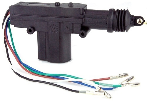 |
| |
|
|
|
|
|
|
|
Aug 12, 2023 10:41:16 GMT
|
|
Hi, I'm no expert but are five wire units used as the master, relaying lock/unlock signals to slave units on other doors that only utilise three of the wires? Just a suggestion.
Colin
|
| |
|
|
|
|
|
Aug 12, 2023 11:36:45 GMT
|
|
I was under the impression that if you turned the key in the door, then they would automatically unlock the rest.
But now I'm not sure.
Basically I'm wanting to fit central locking to a classic.
Its already got a good alarm fitted, which has the ability to control the locks, but I was going to add a modern touch with an inside 'Lock / Unlock' button using a latching change over relay.
Ideally I would like the drivers door to automatically unlock the passenger one if I use the key, although I guess its not critical.
|
| |
|
|
jimi
Club Retro Rides Member
Posts: 2,220 
|
|
Aug 12, 2023 14:15:27 GMT
|
|
I have pictures of one that looks the same as that, so I can see where the wires go and what they do. I'll post them up as soon as I can and we can figure it out. Do you have a multi meter ?
|
| |
Last Edit: Aug 12, 2023 14:15:58 GMT by jimi
Black is not a colour ! .... Its the absence of colour
|
|
|
|
|
Aug 12, 2023 14:31:27 GMT
|
|
Thanks, I do yes.
But currently all the car has is an alarm system, I'm still at the design stage for the locking!
|
| |
|
|
jimi
Club Retro Rides Member
Posts: 2,220 
|
|
Aug 12, 2023 16:11:17 GMT
|
|
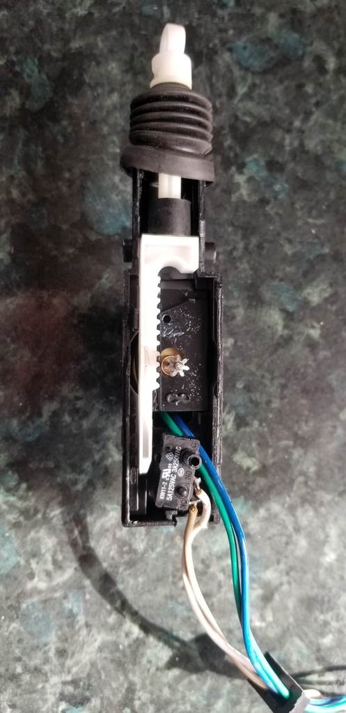
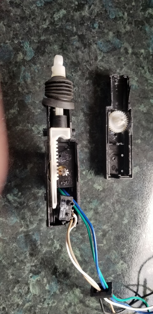
Ahh, right. On the one I have the wire functions are as follows:
Green & Blue are the motor power so + to green and - to blue drives the actuator one way, reversing the polarity drives it the other.
The other 3 wires go to a micro switch inside the actuator
Black = Common
Brown = N/O (normally open)
White = N/C.(normally closed)
I'll post a couple of pics later. The actuator was from a cheap ebay kit I fitted to my son's Cinq
AFAIK its a pretty common configuration for this style actuator.
|
| |
Last Edit: Aug 12, 2023 16:11:50 GMT by jimi
Black is not a colour ! .... Its the absence of colour
|
|
jimi
Club Retro Rides Member
Posts: 2,220 
|
|
Aug 12, 2023 17:43:58 GMT
|
|
|
| |
Black is not a colour ! .... Its the absence of colour
|
|
jimi
Club Retro Rides Member
Posts: 2,220 
|
|
Aug 12, 2023 18:42:44 GMT
|
I wouldn't bother with components, just buy a kit. This is the kind of thing I bought Linky at £25 you can hardly go wrong. |
| |
Black is not a colour ! .... Its the absence of colour
|
|
|
|
|
Aug 13, 2023 17:59:06 GMT
|
I wouldn't bother with components, just buy a kit. This is the kind of thing I bought Linky at £25 you can hardly go wrong.
Thanks, I've seen those kits, but I'd rather avoid.
The previous owner paid to have a Clifford 650 alarm installed, (quite a lot of money actually) and it should be able to run a central locking system.
However the manual is more geared towards interfacing with existing ones, not a fresh install.
I'm hesistant to add some eBay kit, because it seems to be a bit of a weak link in the system, and plus I don't want to have to carry two key fobs with me!
I'll keep researching & post it on here if I find the answer!
|
| |
|
|
mk2cossie
Club Retro Rides Member
Posts: 3,060  Club RR Member Number: 77
Member is Online
|
|
Aug 13, 2023 18:25:30 GMT
|
Surely the 5 wire actuators are for vehicles without central locking, with 2 of the wires on said actuator for the alarm fitted to lock/unlock as required. And the other 2 wires to feed a central locking relay for the rest of the actuators? Certainly how the remote central locking fob on my car was wired up, as I had to retro fit a 2 wire actuator on my drivers door, to actuate the standard fitment central locking switch  |
| |
|
|
|
|
jimi
Club Retro Rides Member
Posts: 2,220 
|
|
Aug 13, 2023 20:22:09 GMT
|
|
2 wire actuators give no indication of the actuator position 5 wire actuators do via an internal micro switch) other than that they are the same If you buy a 4 door kit you normally get 2 x 2 wire (rear doors) and 2 x 5 wire (front doors) One reason is so they can be interfaced with the key of the door lock (cars without central locking don't normally have key switches) so if you unlock with the key, the actuator is moved and operates the micro switch, kits normally come with a control module that controls operation ( and provides the polarity reversal) and normally has the facility to connect to an alarm system.
I may have a manual for a Clifford 650, I'll have a look.
|
| |
Black is not a colour ! .... Its the absence of colour
|
|
jimi
Club Retro Rides Member
Posts: 2,220 
|
|
Aug 13, 2023 20:49:08 GMT
|
|
I have a copy of a installation manual for a Clifford Concept 650 mk2, it has information on connecting central locking actuators including aftermarket ones, any use to you ?
I have a few other Clifford manuals if you have your exact model description I'll have a look at what I have.
|
| |
Black is not a colour ! .... Its the absence of colour
|
|
mk2cossie
Club Retro Rides Member
Posts: 3,060  Club RR Member Number: 77
Member is Online
|
|
Aug 13, 2023 22:11:04 GMT
|
You'd think this info would be easy to come by, but apparently not. The 5 wire style lock actuators for central locking, I want to wire one to actuate the passenger lock when the drivers lock is opened. The wiring according to Car Builder solutions: BROWN - Lock Input BLUE - Unlock Output WHITE - Unlock Input Black - Earth Green - Lock Output The brown and white are quite clear, supply momentary 12v to either lock or unlock the door. The Blue and Green are confusing, because they are described as lock output, but as there is no 12v input to this actuator, even though they say output, I guess that what they do is temporarily connect to the ground whenever your either turn the key, or actuate the solenoid? So to make it work I need to setup the system so that it is grounding the unlock or lock side of the passenger actuator?  Wire up the inputs to activate the solenoid. The outputs go from the master solenoid (usually on the drivers door) to activate the rest when the key is used (hopefully that makes perfect sense) |
| |
|
|
jimi
Club Retro Rides Member
Posts: 2,220 
|
|
|
|
That actuator looks exactly like the one I have split open in my pictures, if it is then it's not a solenoid, it's a motor that drives a rack in/out, there's only two wires connected to the motor and in/out is by reversing the motor input polarity. There's no internal connection between the motor and the other 3 wires, they only go to the micro switch. It's entirely possible it's not the same, but that's easily checked with a meter. This is mine closed up 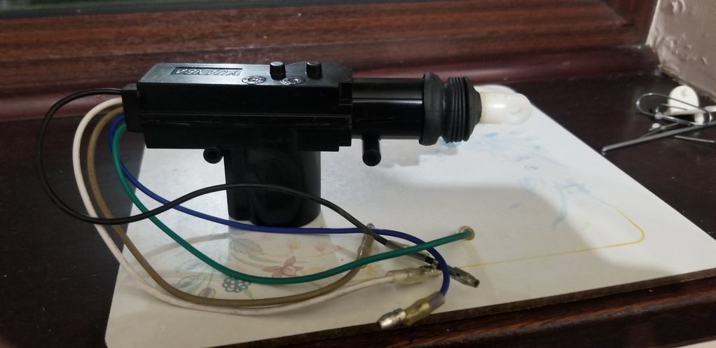 Just checked on the car builders website and it says Which is the same as mine, so I'd say that the other 3 wires are the same as well, so you need relays/control module to implement control |
| |
Last Edit: Aug 14, 2023 11:22:17 GMT by jimi
Black is not a colour ! .... Its the absence of colour
|
|
|
|
|
|
|
OK, I think I've got it. The wording on the website is a bit confusing. So: Green / Blue: Push pull to activate the solenoid. This in turn changes the other wires Brown: Lock input: Connects to Ground when door is locked White: Unlock Input: Connects to Ground when door is unlocked Black: Ground wire so that the two above can be grounded. As the Lock / Unlock input wires will provide a constant connection to ground, I need something a bit more complicated then a direct connection with a relay. I found a wiring diagram for a Honda Civic lock control module that is easy to find, and pre canbus, so works stand alone. 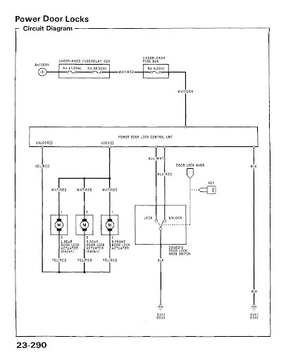 In this case, the door lock is not motorised, it simply signals the module to unlock the other doors when the key is turned. But if I replace this lock switch with our 5 wire solenoid & wire it like below, then I think it will work: 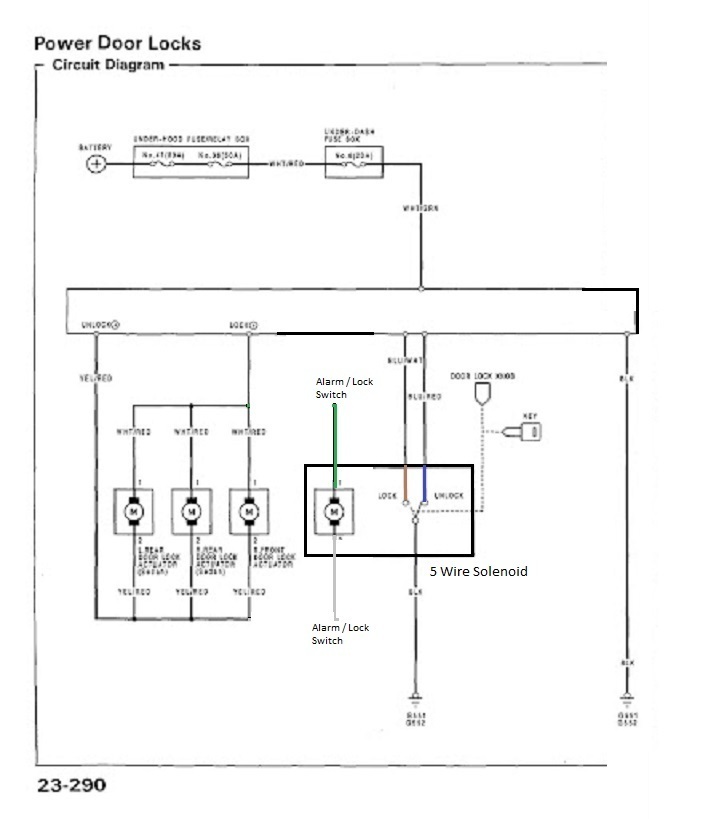 In my case, I can remove two of the locks as I only have two doors. And when I actuate the drivers lock with the alarm, an internal switch or just turn the key, it should do the passenger side as well. |
| |
|
|
jimi
Club Retro Rides Member
Posts: 2,220 
|
|
Aug 14, 2023 11:04:34 GMT
|
👍 Yes, the website wording is very confusing, I think the 5 wire descriptions are referring to control module connections. As long as the Honda module reverses the motor polarity (looks like it does according to the drawing) then the way you have it drawn should work.  The black wire is common, can be ground if that's what you need. |
| |
Last Edit: Aug 14, 2023 11:25:07 GMT by jimi
Black is not a colour ! .... Its the absence of colour
|
|
|
|
|
Mar 19, 2024 14:39:58 GMT
|
Is it possible to install a keyless entry system to this type of central door locking system? If it is, can you at least give me a guide on wiring installation. It has 5 wires and I'm confused which is the lock/unlock trigger wires. By the way, this is attached to a Japanese model car Nissan Otti. Your help will be very much appreciated. Thanks. 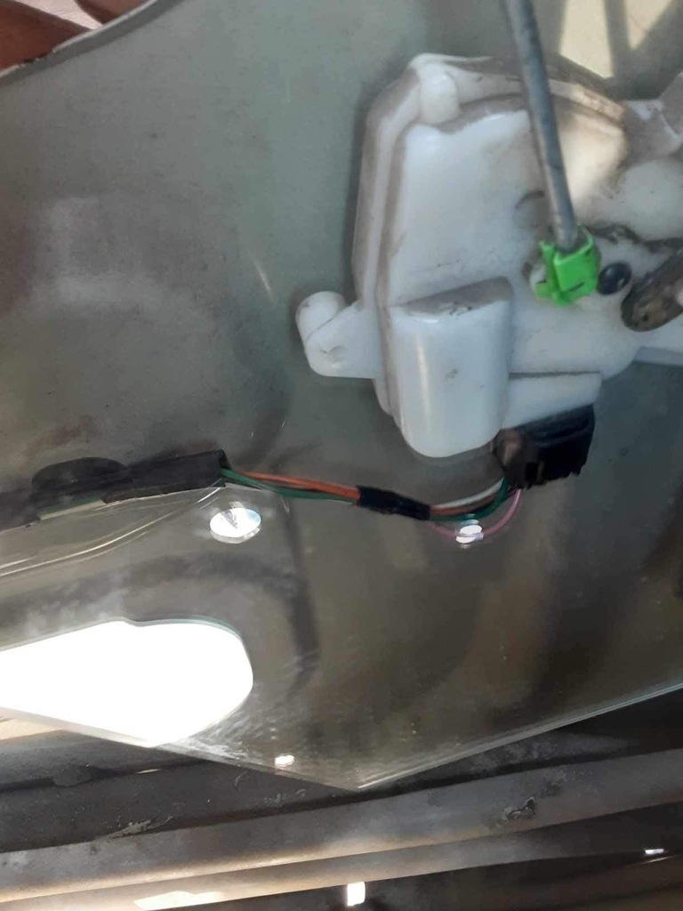 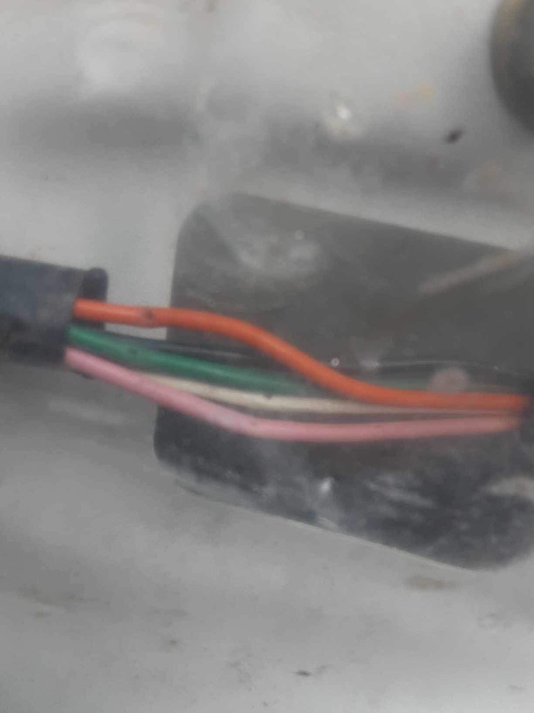 |
| |
|
|
|
|
|
Mar 19, 2024 17:09:26 GMT
|
|
as that has 5 wires you may not need to change the motor at all, but you will need to figure out what the wires are doing and where they go.
|
| |
|
|
|
|
|
|
|
|
The wires are for the main central door lock located on the driver side which lock/unlock the doors using a key. These 5 wires connected to the solenoid door lock( shown on the picture), along with the power window, speaker and side mirror wires were all together connected to a single 24-pin connector at the other end under the dashboard panel which is connected to another connector coming from a fuse box or relay switch box, i suppose (not sure). I don't know which of these are the lock/unlock trigger wires where i can tap the wires of the keyless entry kit i bought. Thanks
|
| |
Last Edit: Mar 20, 2024 3:25:00 GMT by ermil
|
|


