Enbloc
Part of things
 
Posts: 399
|
|
Feb 19, 2023 19:21:33 GMT
|
This was my previous pedal set in the car. 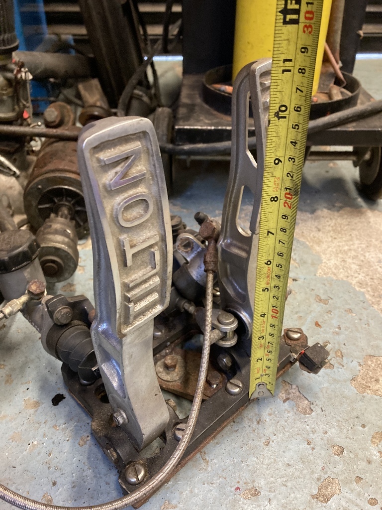 I always loved this Tilton set in the car but it had a few flaws. The first was its position. It is a floor mount set which ordinarily would mount on/above the floor but because of my floor layout meant it needed to be half under the floor to get the pedals in the correct position. This meant the floor board had to be peppered with clearance holes and slots and also had to be split lengthways to be able to actually fit it back around the pedals. Even after many attempts to seal around the pedals I still had the heat, cold, dirt, dust and fumes leaking through. The factory pedal set isn’t actually that far removed from this scenario as it is also mounted under the floor with the pedals looping up through the floor board. The balance bar was a good idea at the time but after setting the balance I’ve never moved it and I’ve also never had the remote adjuster connected either. Adjustments or maintenance would also mean removing the floor again. 🤦♂️ This basically leads me on to my hatred of anything mounted under the floor. It’s a total pain and why the battery, also factory fitted under the floor, was moved some time ago. I guess all of the above is why the manufacturers also stopped mounting components under the floor in the 50’s or maybe because of the move over to monocoque construction? 🤷♂️ You’ll also notice a tape measure against the pedal. With it out the car I thought I’d work out the pedal ratio. 5.25:1! Well that would explain the heavy pedal. The new new pedals will be a much more manual brake friendly 7:1 ratio. My choice of replacement was this universal Wilwood under dash swinging set. It is also single master cylinder and hydraulic clutch. 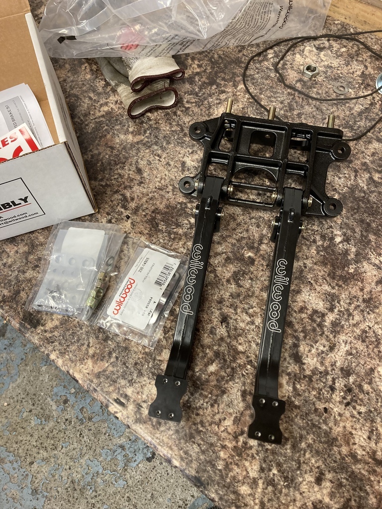 The supplied pedal pads are adjustable. This is good for me as I needed to gain as much clearance as possible between the pedal arms as the steering column would pass between them. 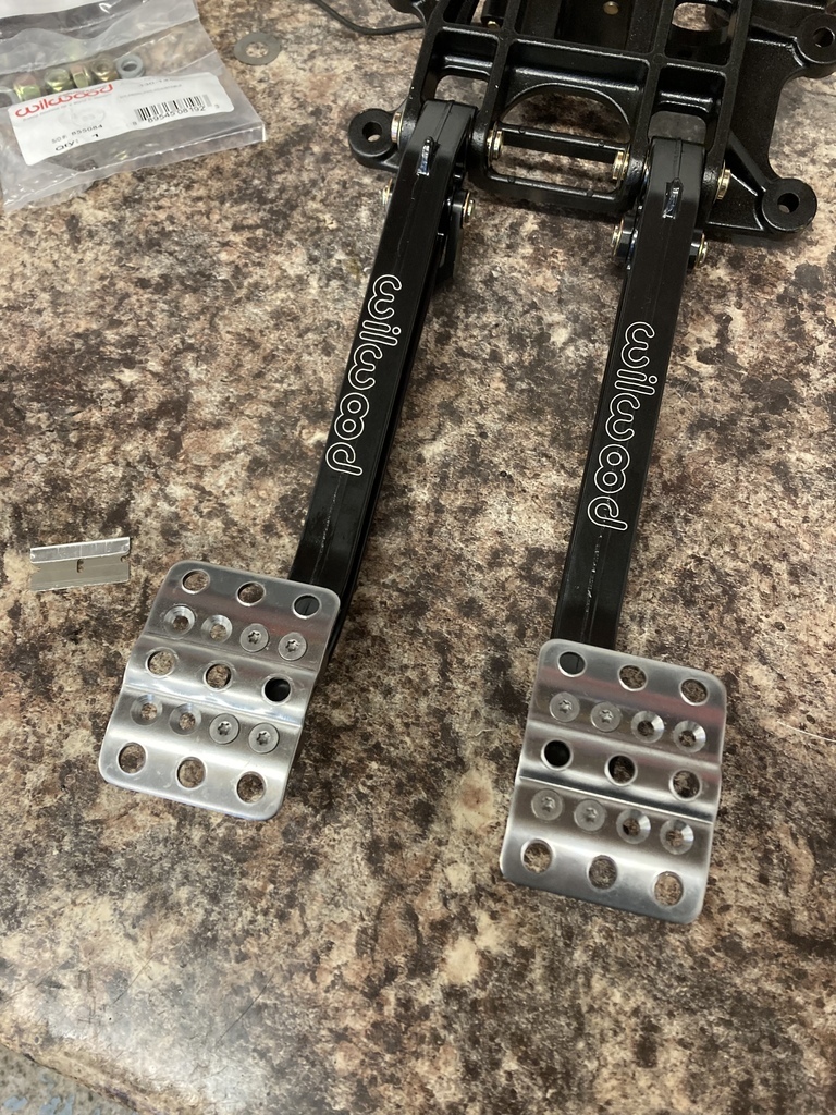 The pre-fitted cylinder studs were removed as they would be in the way during mockup. I don’t know what locktite was used but it took two of us hanging off the pedal assembly to get the studs out. 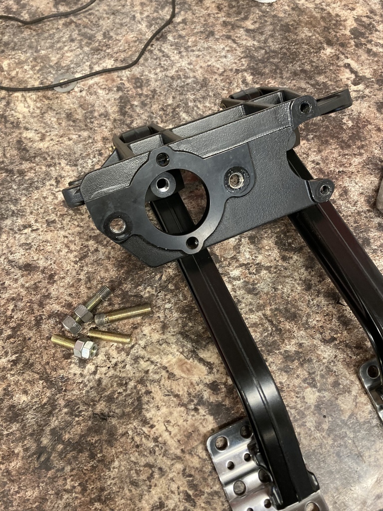 The steering column and original pedals were bolted back in so I could measure them for pedal position from some fixed points around the foot well. For all their faults the position of the Tilton set was spot on and one of the few cars I could actually heel/toe in! 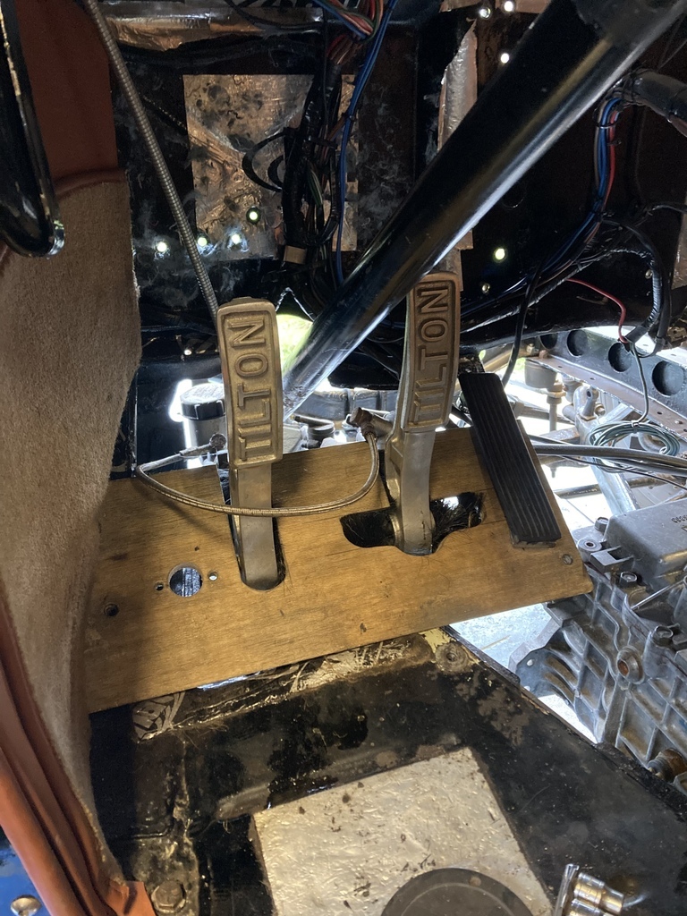 Initial placement seemed to put it on the vertical section of the firewall which simplified things and worries of the fuse box being in the way was a nonissue but the main loom from the fuse box, which runs down the firewall, may need rerouting. The fuse box and loom were unbolted from the firewall to avoid putting the grinder through them! 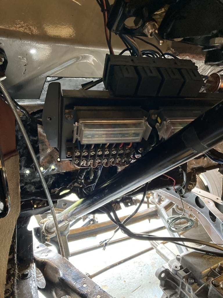 Trying to protect the interior. 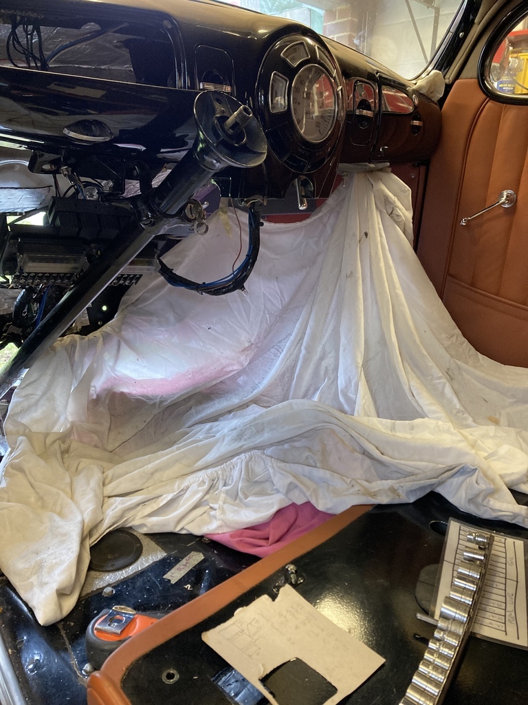 First cuts marked out. We decided, as a starting point, to take a 6” deep by the width of the original firewall stamping as a starting point. The reason for the hole is the pedal assembly needs to moved forward into the car around an inch for the correct pedal placement. 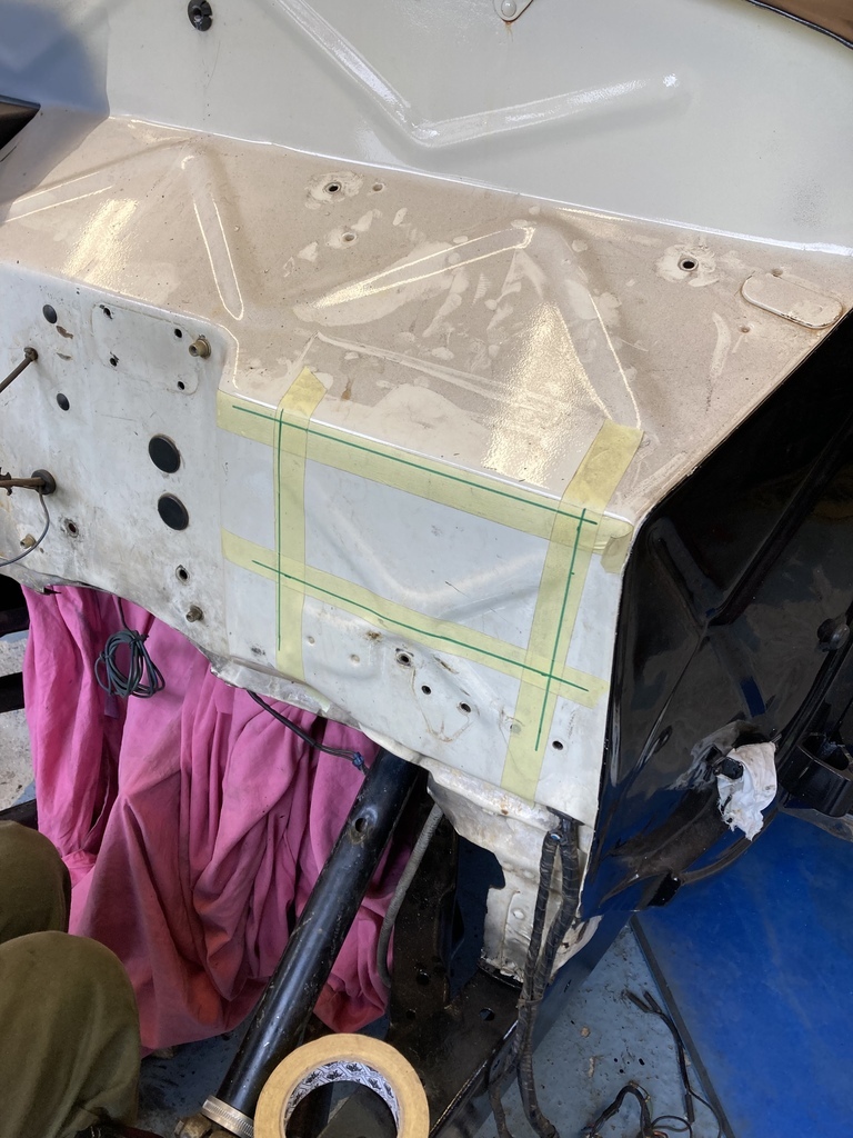 Cut. 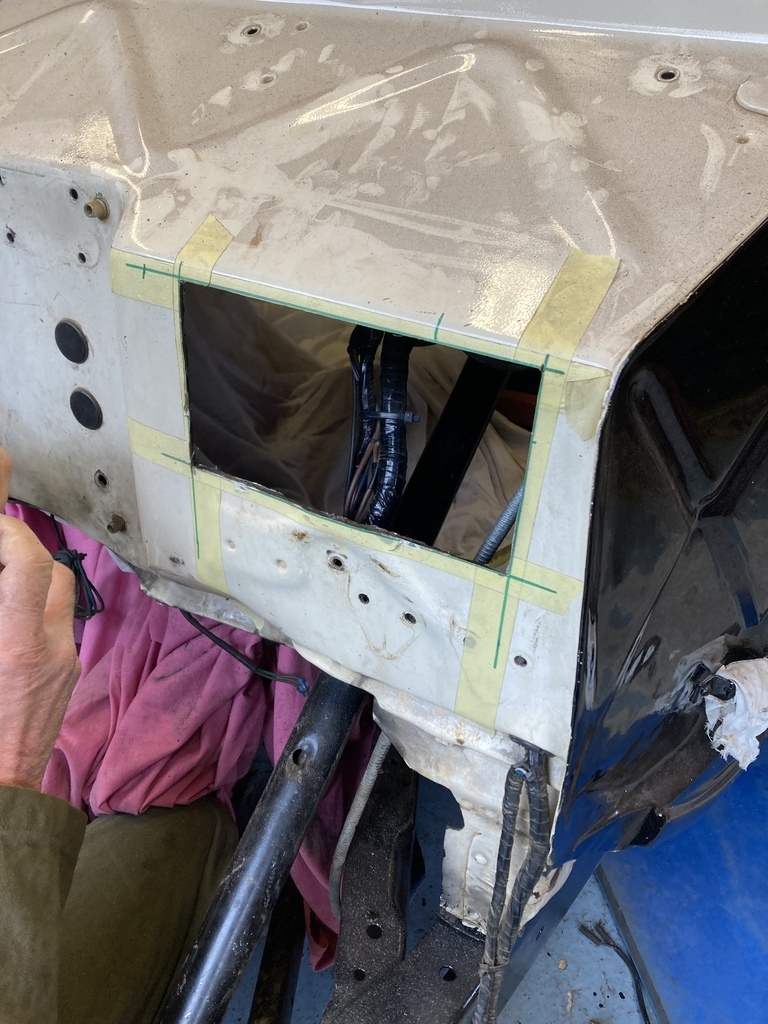 Another mock up showed the hole didn’t need to be as wide as it had been made but the top edge had to be moved into the horizontal section of firewall to loose any potential clearance issues with the master cylinders and/or reservoirs that will be mounted this side of the firewall. 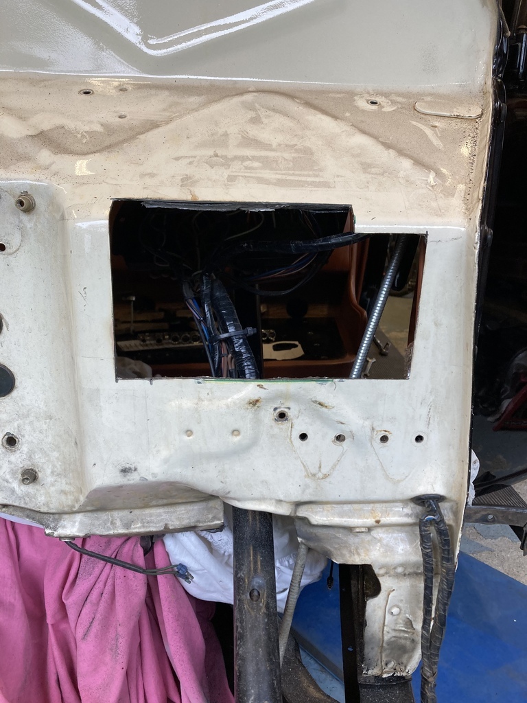 Some temporary straps were made at the correct depth into the car. The pedals could now be bolted in as a final check for placement. 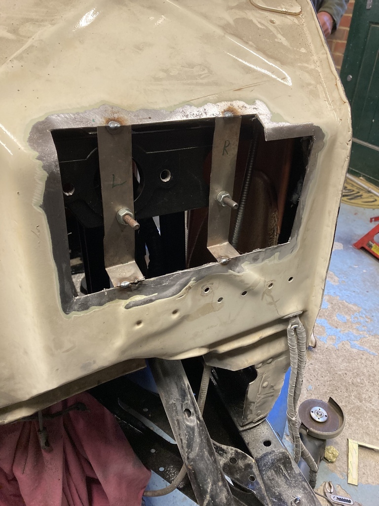 The seat was put back in and really happy with that. Full swing on both pedals, no clearance issues with the column and the original accelerator pedal position seems spot on as well. 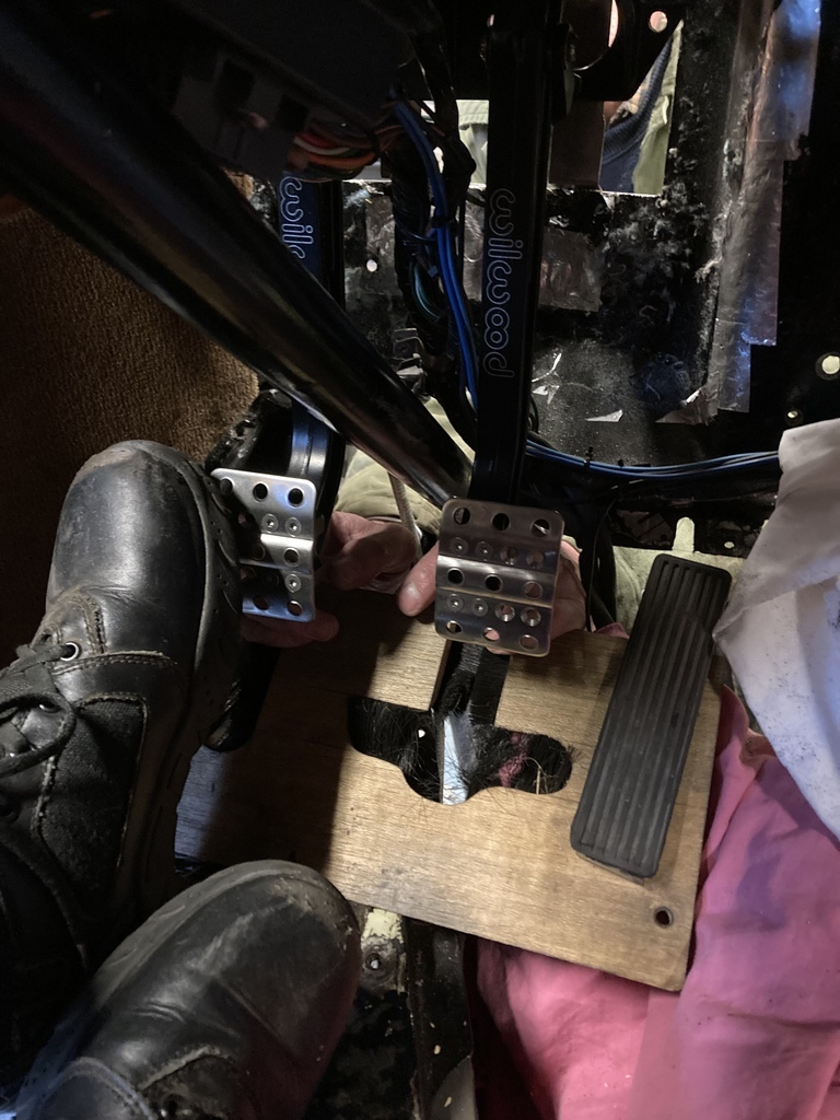 Finalising the pedal position meant that I now had the joy of scrapping the dynomat off the firewall ready for welding. 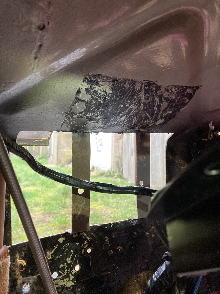 A quick patch was made to go back in the firewall to square up the hole. 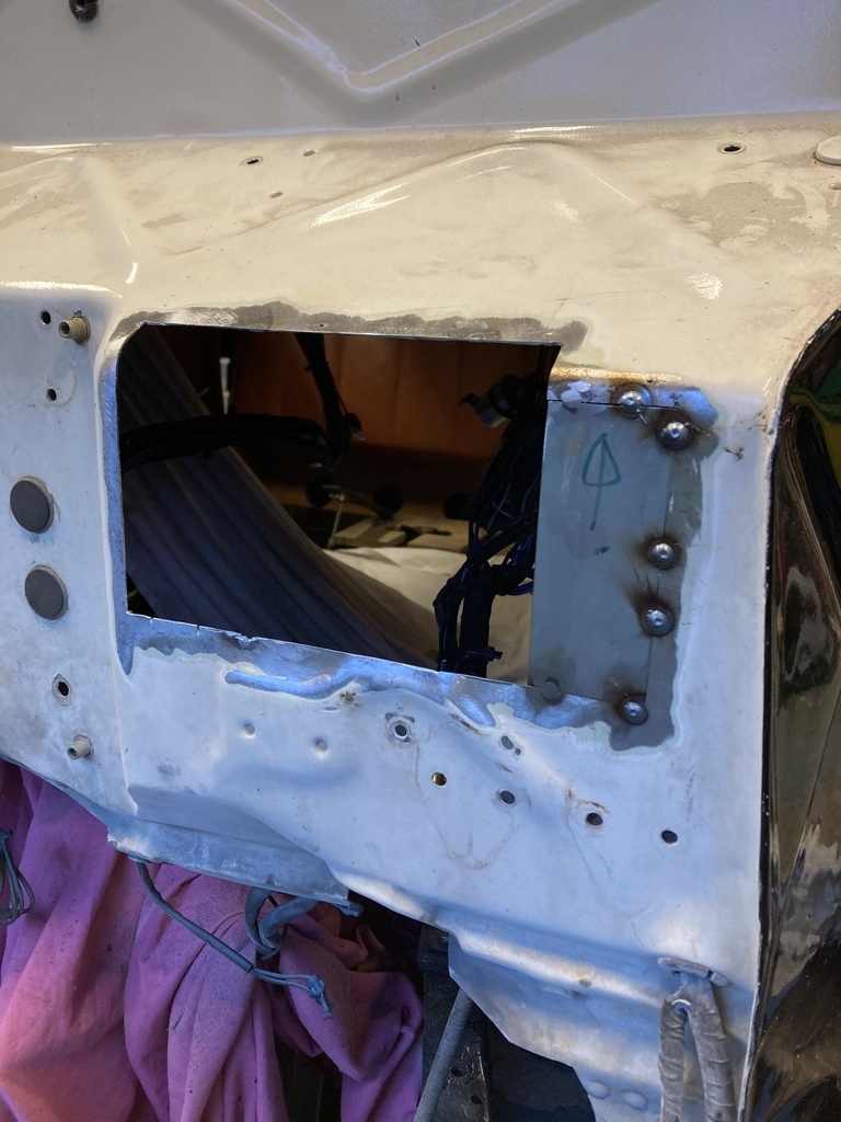 Next was to make the new mounting surface for the pedals. This would basically be a 3 sided box. The firewall is 2mm or what the imperial gauge equivalent is, so pretty chunky to be bending. The basic shape was cut out. 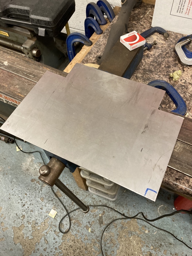 Only having some big angle in the vice to bend with meant we went straight for the heat. Initially trying to use some map gas wasn’t really going anywhere especially as the bottle was running out. So the big guns came out. 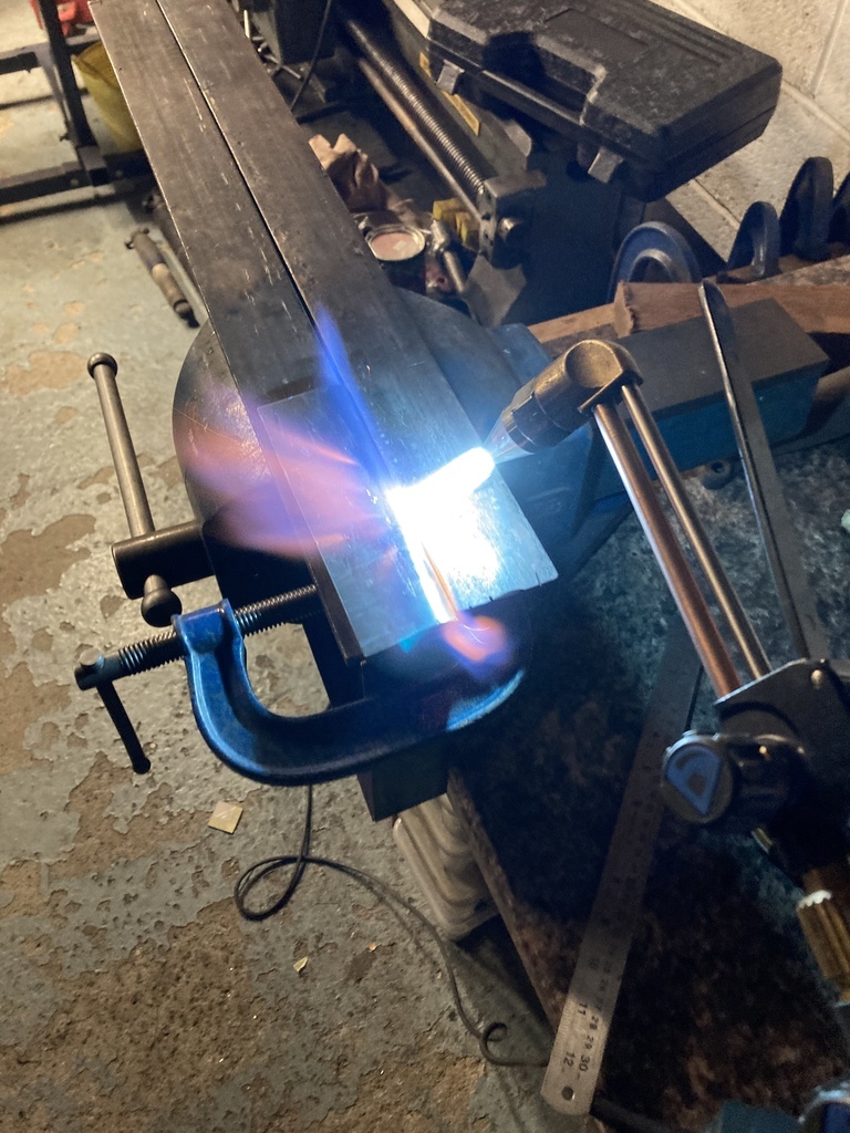 Producing a decent bend. 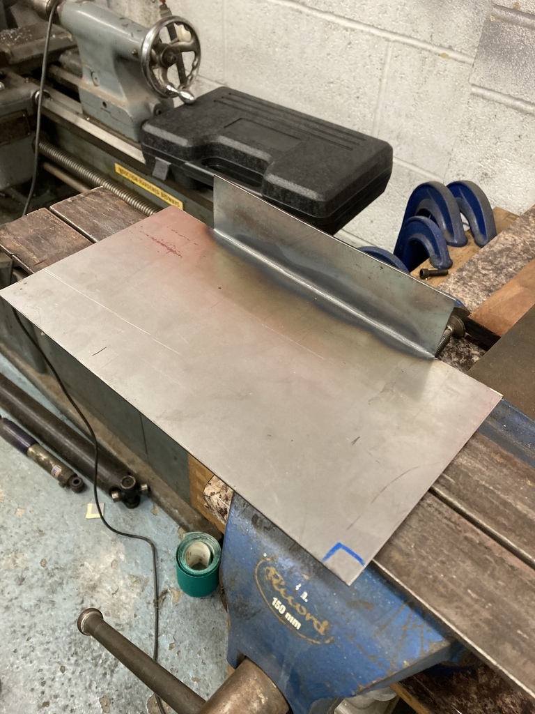 On to the other two sides. Same process. 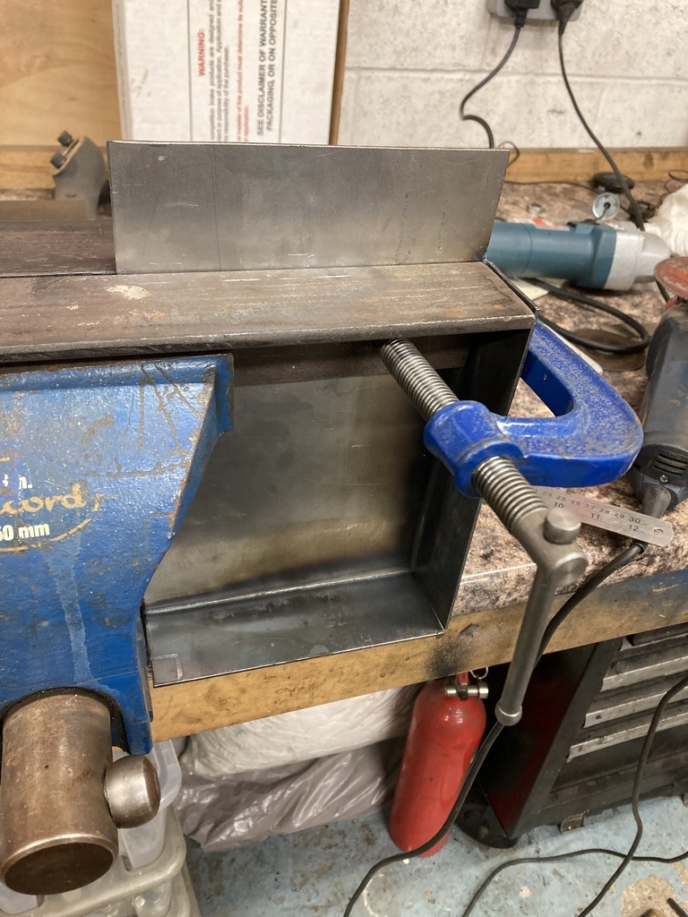 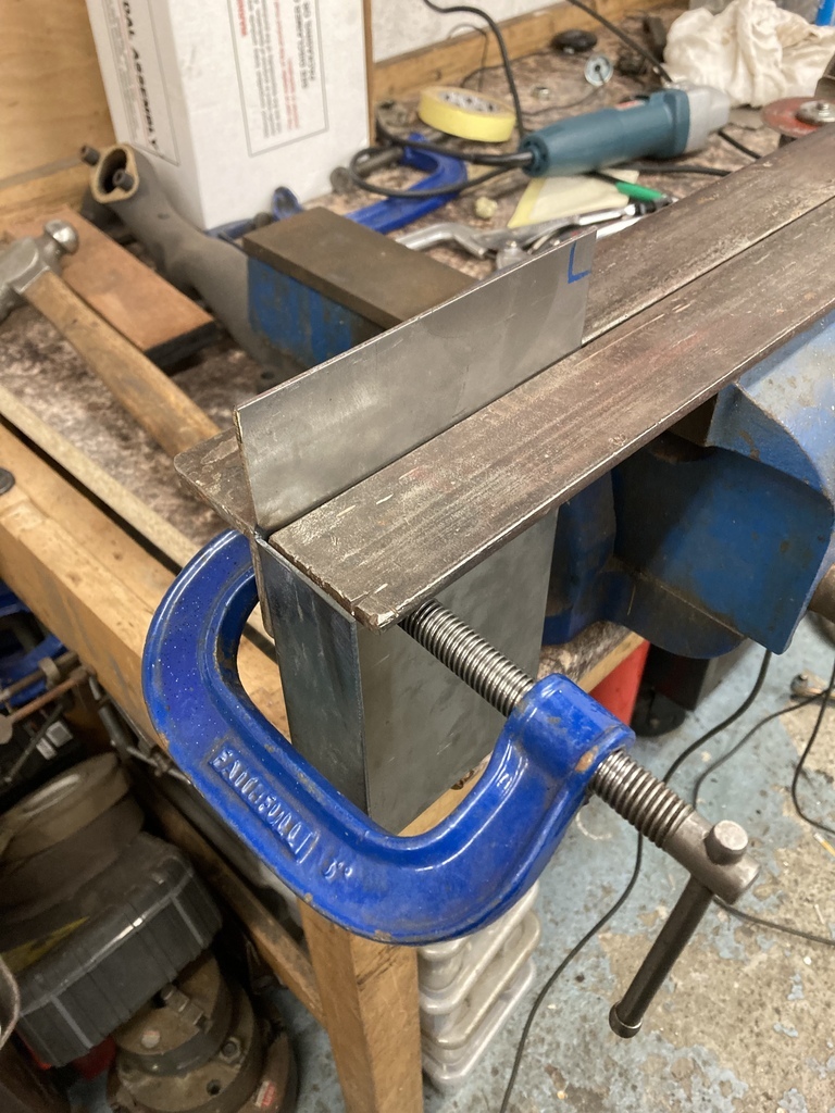 One 3 sided box. 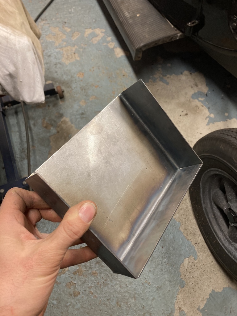 Like a glove. 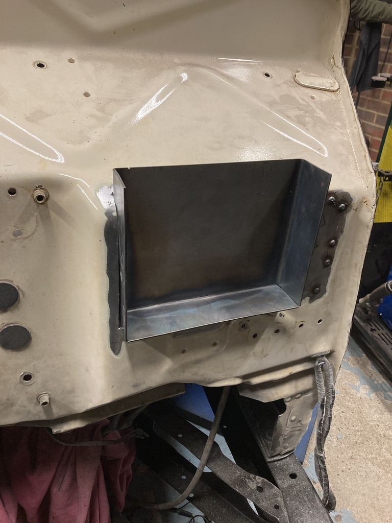 |
| |
|
|
|
|
Enbloc
Part of things
 
Posts: 399
|
|
Feb 25, 2023 19:26:14 GMT
|
Getting the car pieced back together gave me big chunks of the garage back which sent me on abit of a cleaning spree. I should really address this pile. 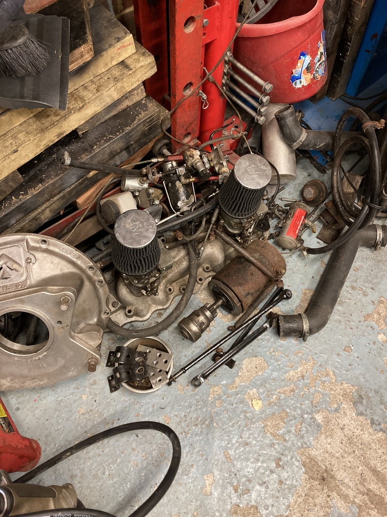 Some of it was destined to go back on, some had served it purpose and some was just rubbish. The first to be dug out was the inlet. I needed to remove part of the PCV setup that was attached to the underside of the inlet before it went into storage. I’ve never been thrilled with this retrofit setup and decided when the time comes I would bend up a neater hardline…. Then the realisation came that there probably wouldn’t be a lot of manifold vacuum present with the new motor. 🤦♂️ 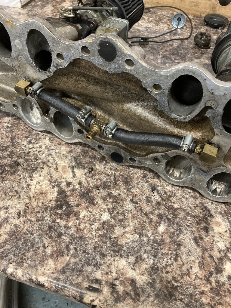 It then went up on Manifold Alley in the spot where the Weber manifold had been. 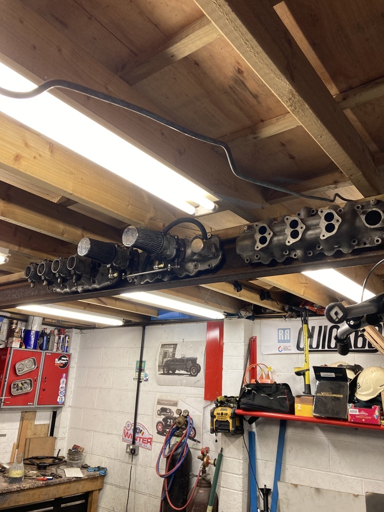 Then I found the front spring anti-squeak pad. Arg 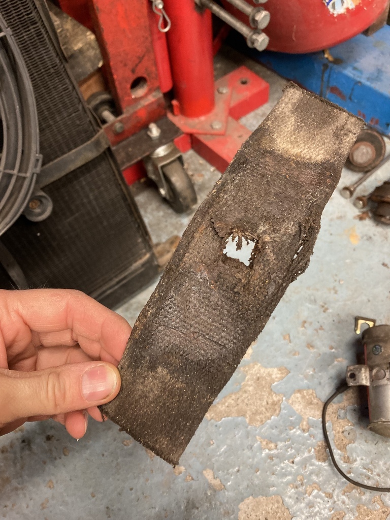 Which meant the front had to be dropped again to get it in. Arg.. 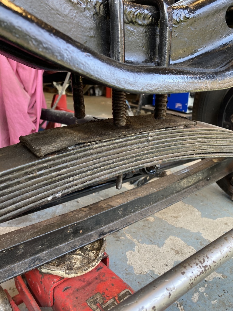 This lot was sent off to the scrap pile. 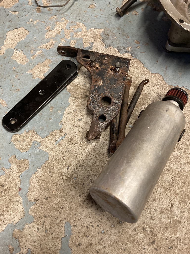 The engine mounts were dropped into position just to give them somewhere to live. 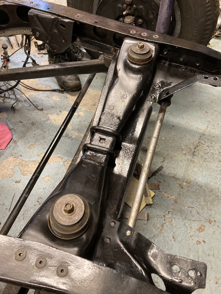 And this stuff will be returning, well maybe not the fuel block. Not sure about this yet as it won’t serve any real purpose anymore but it looks neat on the firewall. I did bin all the stiff and brittle fuel hose that had been hanging off it though. 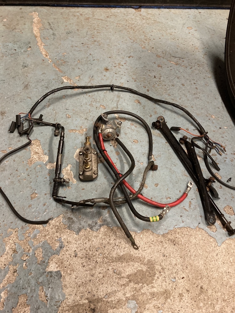 |
| |
|
|
Enbloc
Part of things
 
Posts: 399
|
|
Feb 26, 2023 12:59:38 GMT
|
Back on the pedals, the patch that had been tacked in was fully finished. 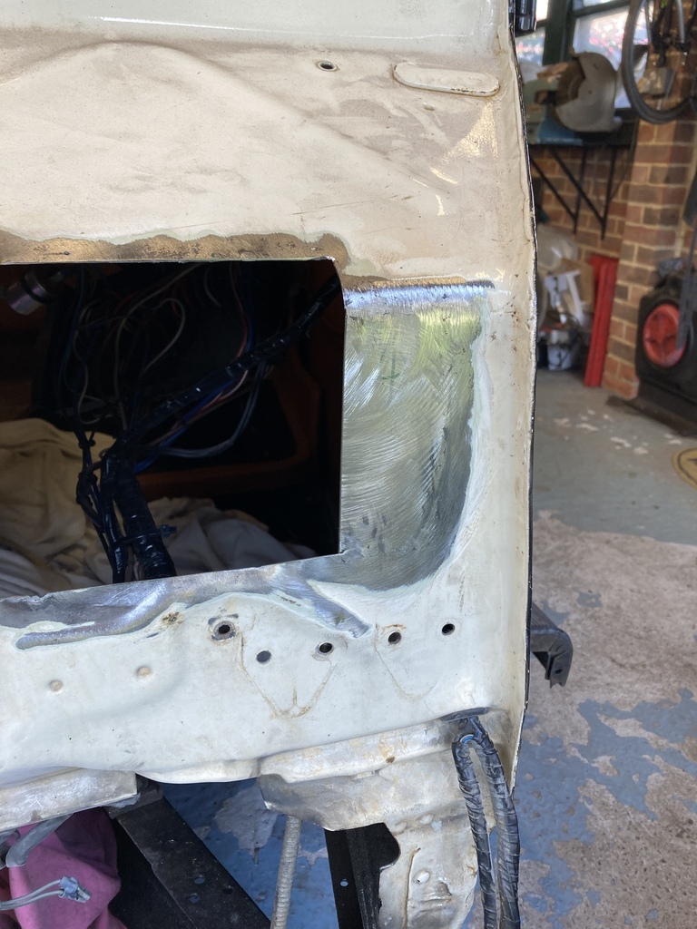 The pedals could now be mounted to the box. Measurements were taken from one of the holes from the mock up to use a datum. 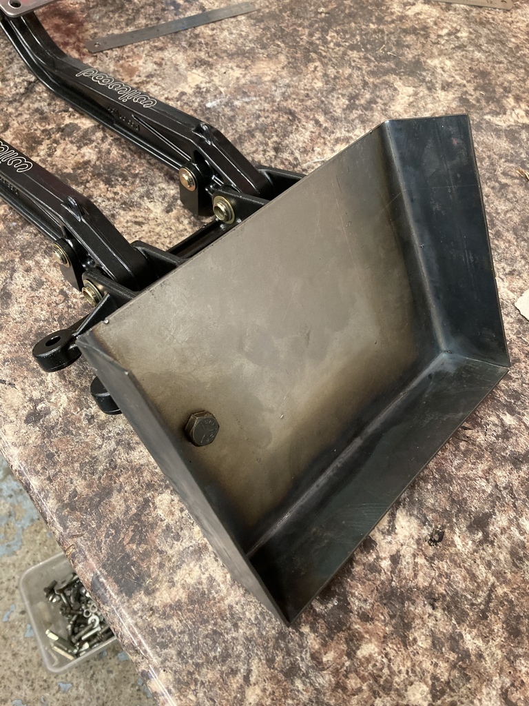 The box and pedals were then mocked up in the footwell to confirm positioning was correct and a second hole marked and drilled. 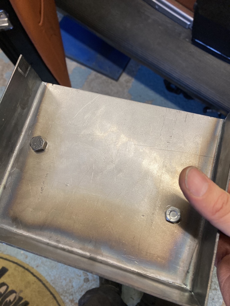 Another mock-up for a sanity check and the final holes could be drilled. 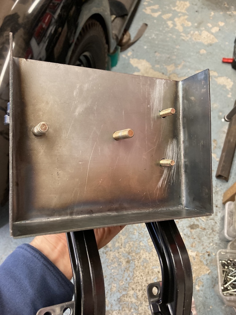 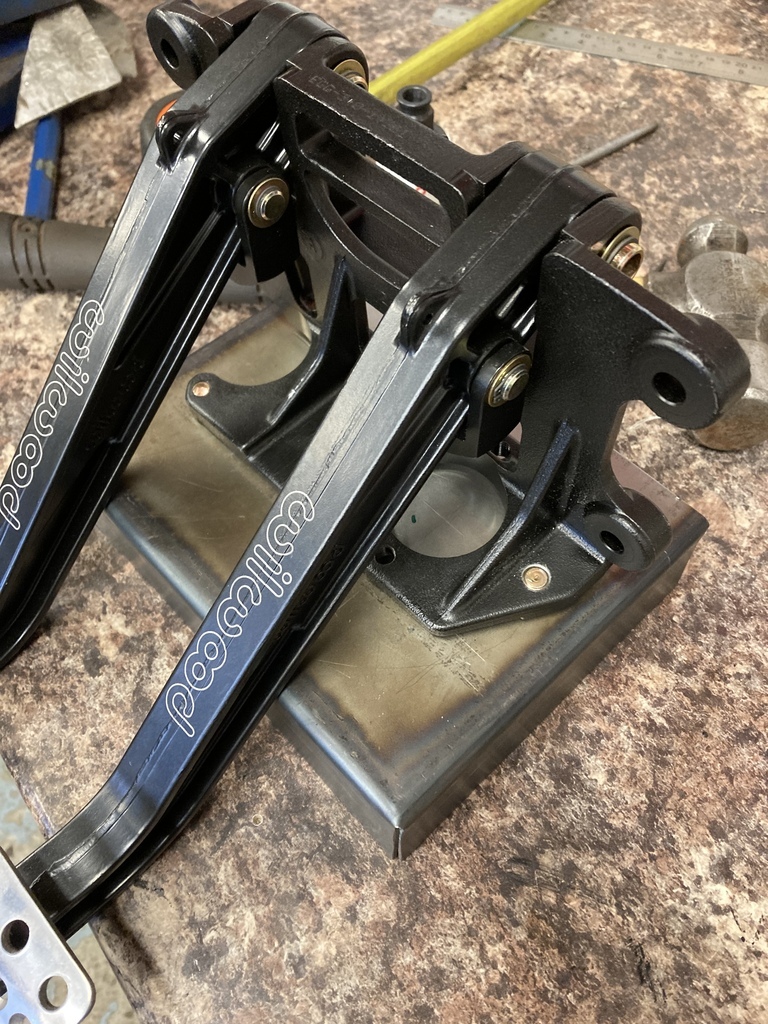 Now the master cylinder holes could be put in. 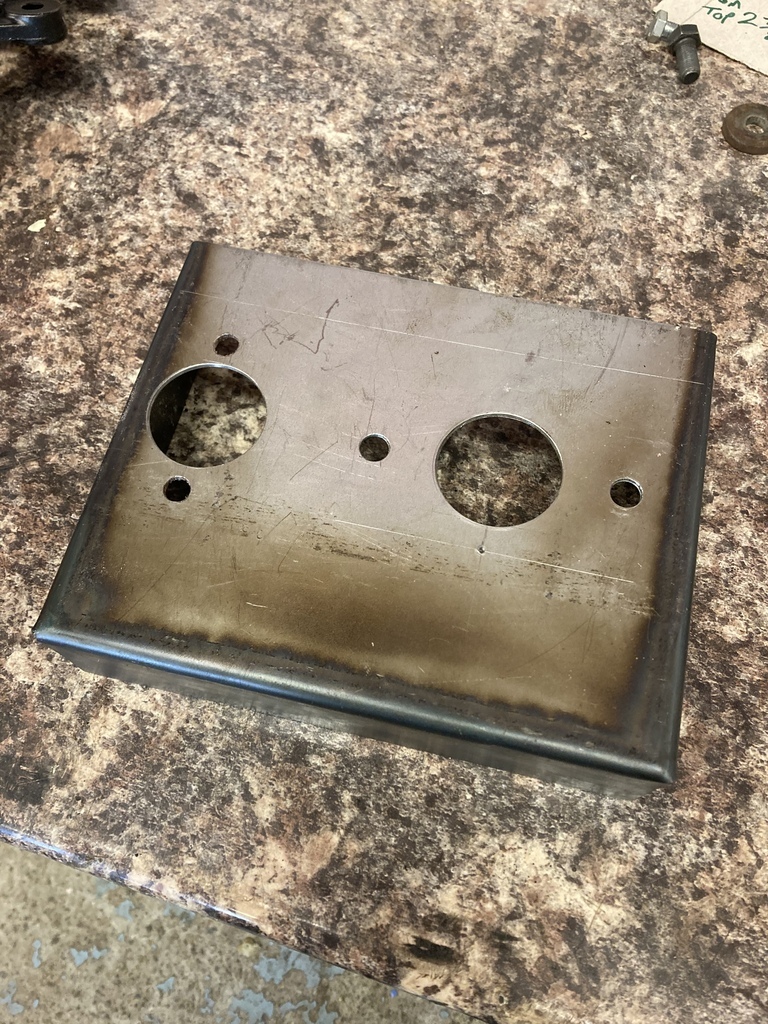 The pedal assembly comes with 4 mounting lugs in the frame. It wasn’t really possible to go up with the mountings so instead went down to try triangulate the assembly to the box. Some CAD mock-ups were tried Which worked on the bench but wouldn’t work when it was fitted to the car. 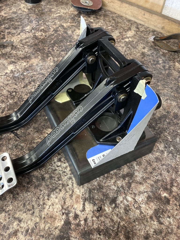 A little repositioning allowed the pedals to be able to slide on and off the braces. 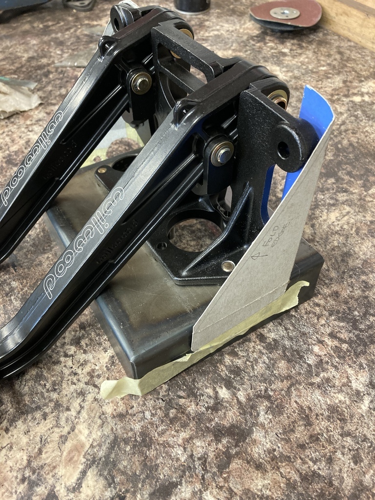 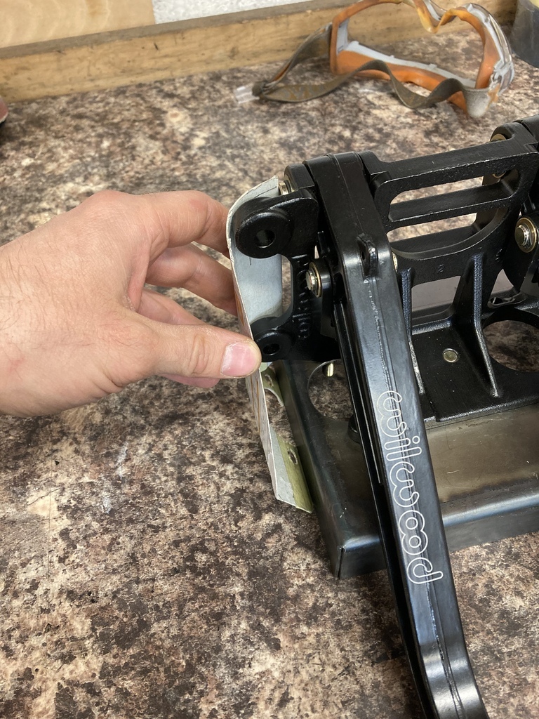 The templates were transferred to 1mm steel. 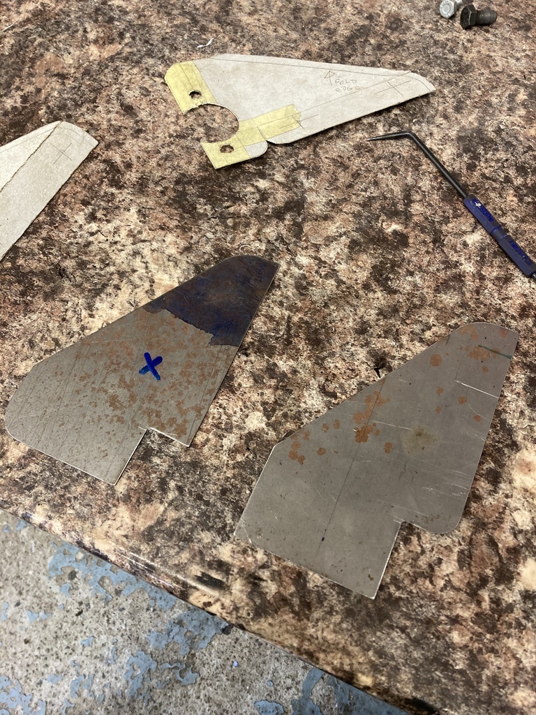 Starting on the RH side first the long side was folded over. 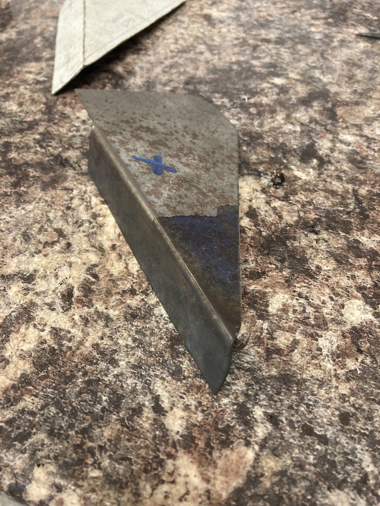 I wanted to try and put as much strength as possible in the side braces rather than just leave them flat. I put a 5mm return all the way around one edge which greatly improved the rigidity. 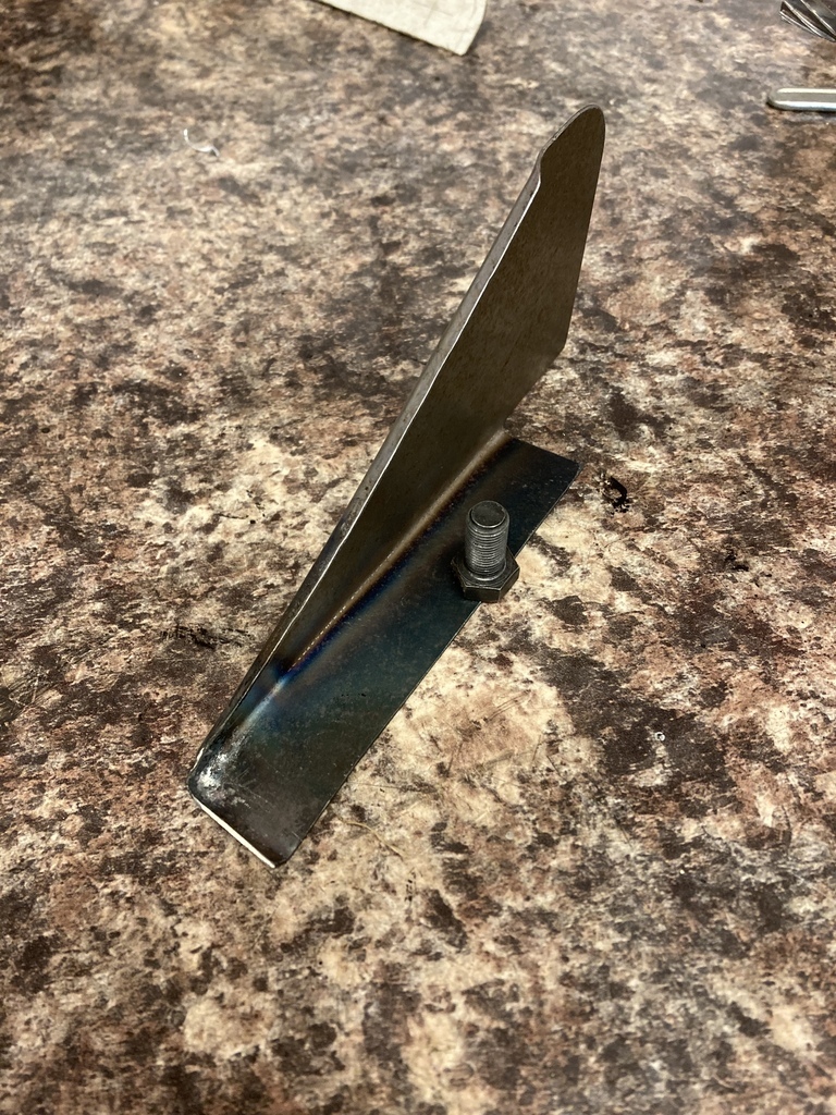 There was a clearance issue with the corner of the brace and pedal frame. 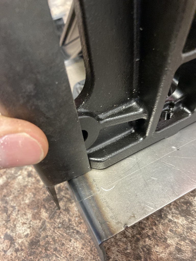 Going through a few options with moving or notching the brace the easiest option was to just notch the pedal frame itself as the section to be removed wasn’t doing alot. 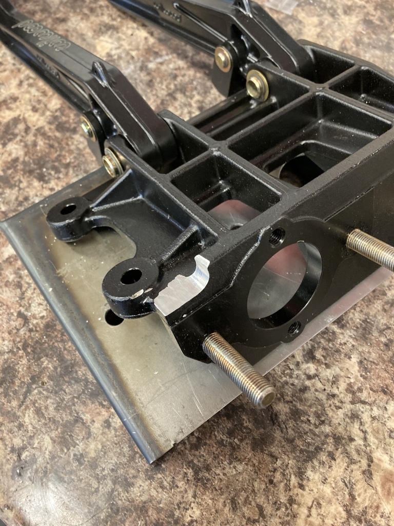 That got things sitting nice. 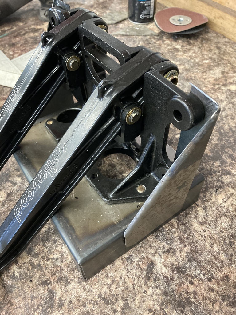 The other side was brought up to the same point. 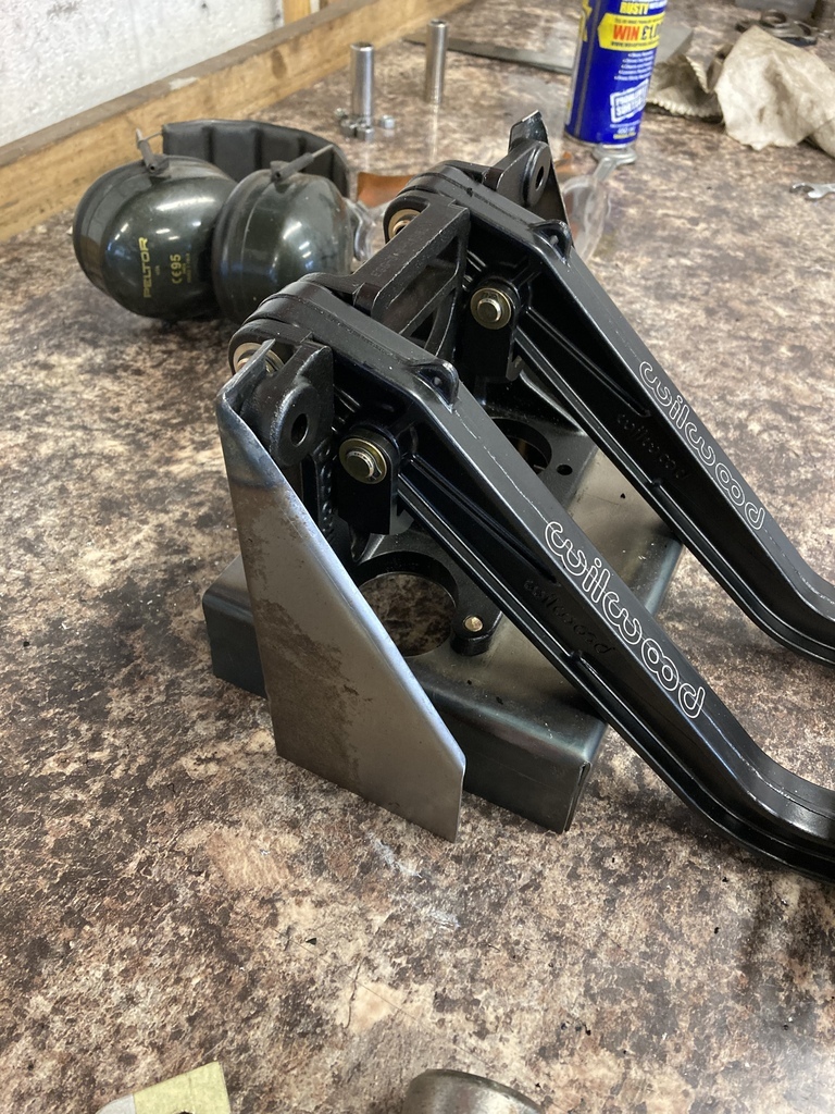 Wanting to add some more rigidity or maybe it was just excuse to get a new tool? 🤔 I bought a new punch and flare which was promptly tried out as soon as it dropped through the letterbox. 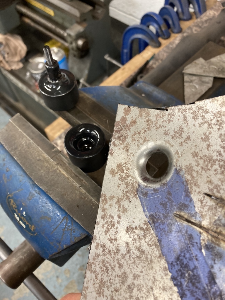 Knowing the absolute diameter of the flare from the practice piece I made a cardboard template so I could centralise it to the triangle. 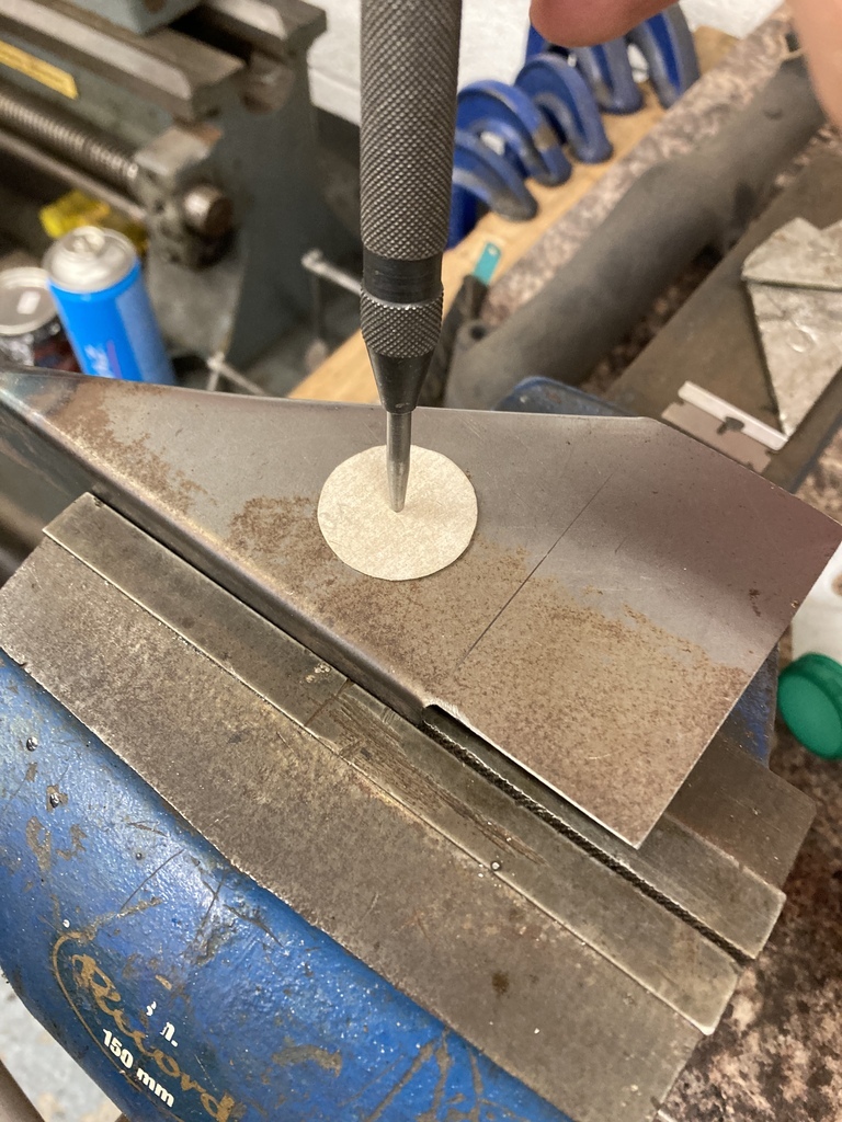 And punched. I had to have the flares outwards for clearance. I don’t know if there is a “standard” for flare orientation but this does seem opposite to what it should be. 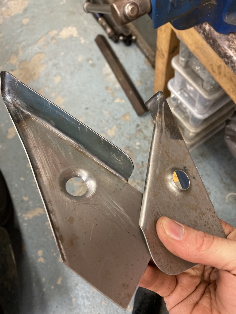 The braces got some notching for clearance. 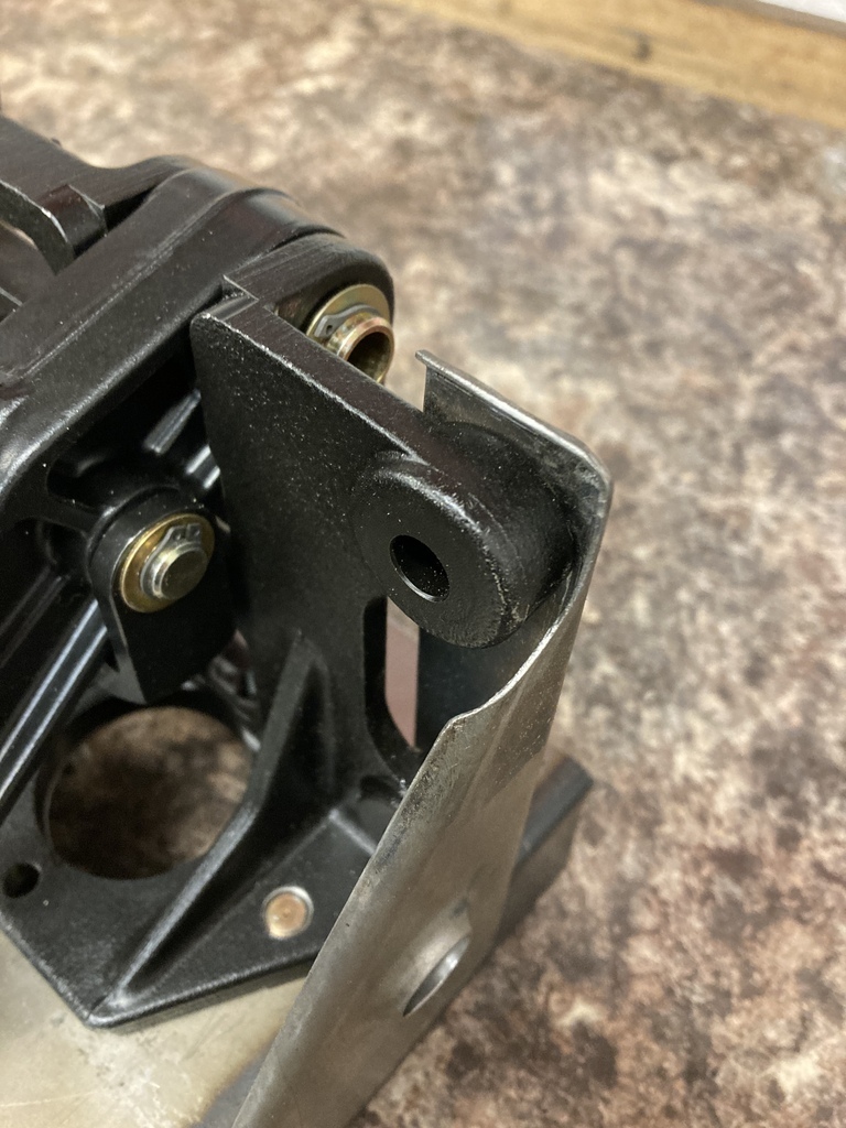 And finished off for ready for welding. Holes for plug welding on the RH side and the short flange on the LH side bent and trimmed to final position. The braces were also drilled for the top fixings and countersunk 5/16 UNF bolts used to centralise the nuts on the brackets in preparation for welding them captive. 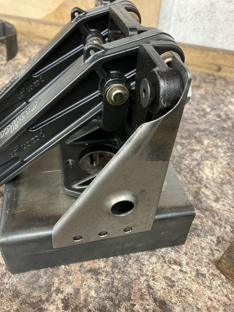 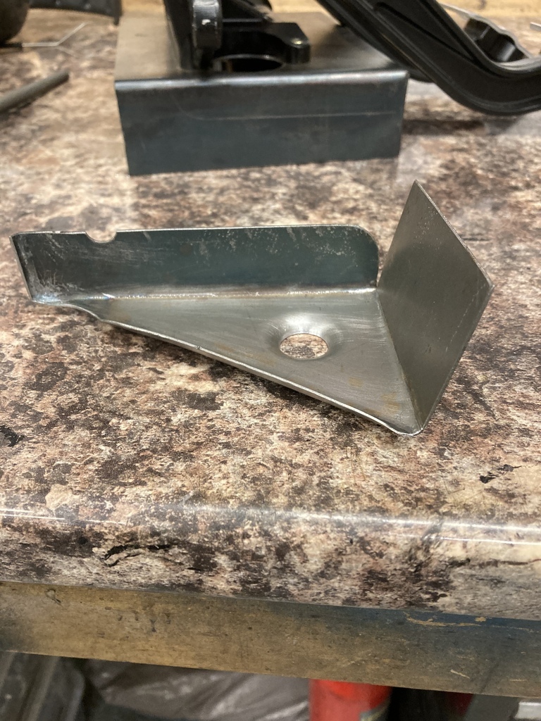 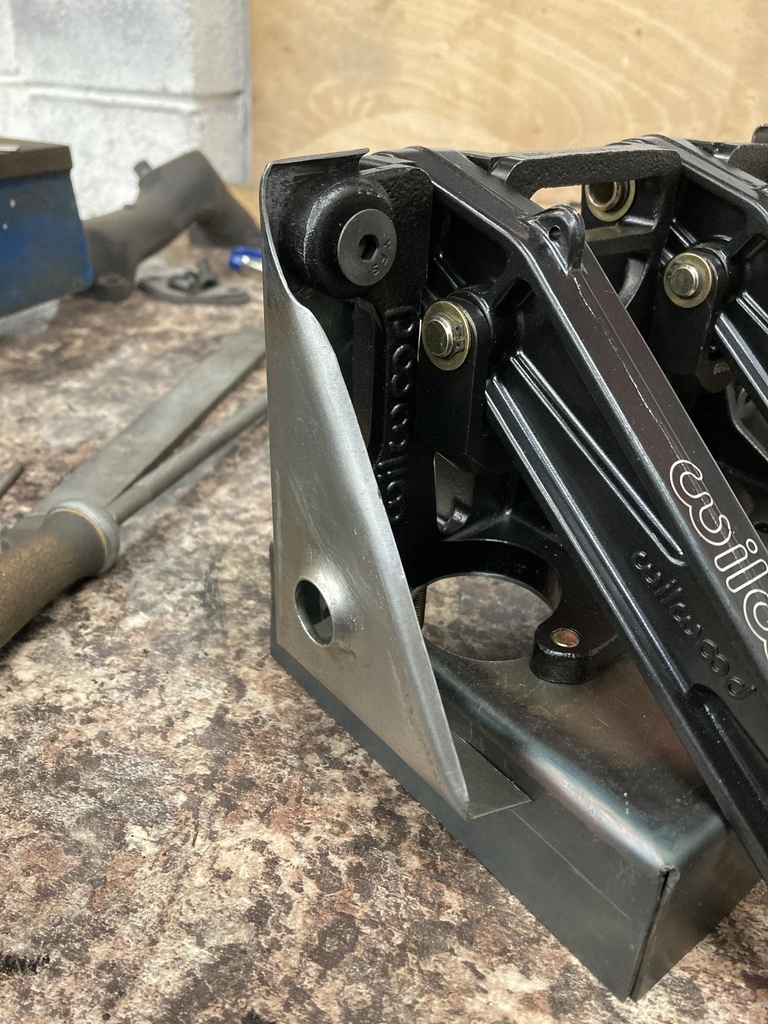 The whole structure was tacked and mocked up in the car again. This was to check that it was possible to fit and remove the pedal assembly from the brackets when actually fitted to the car. With fitment confirmed the whole lot got welded. 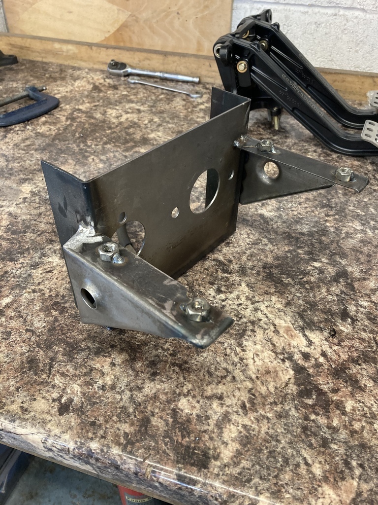 Reassembled for yet another mockup before the final fitment. 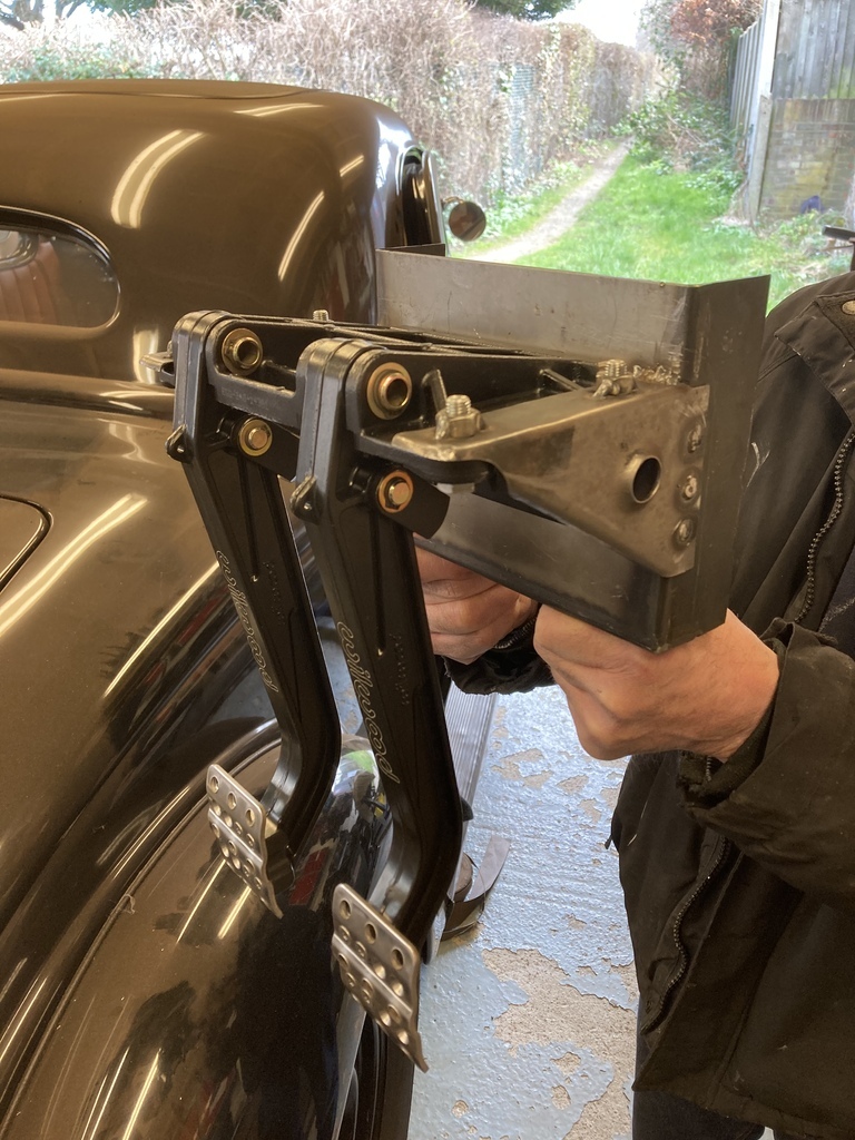 Pedal position to column checked, height checked, straightness checked and again making sure the pedals can be removed when in the car! 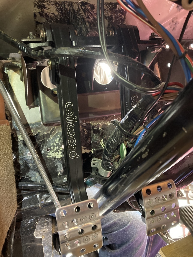 The box was trimmed to the shape of the firewall… 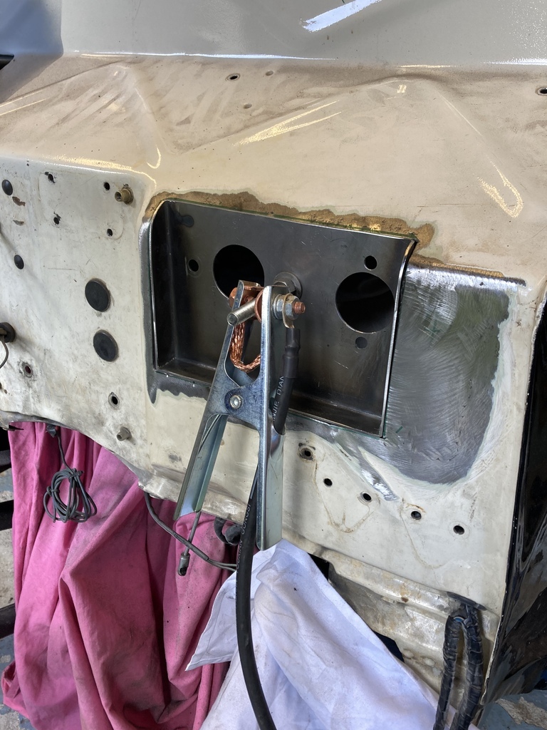 … for final welding. 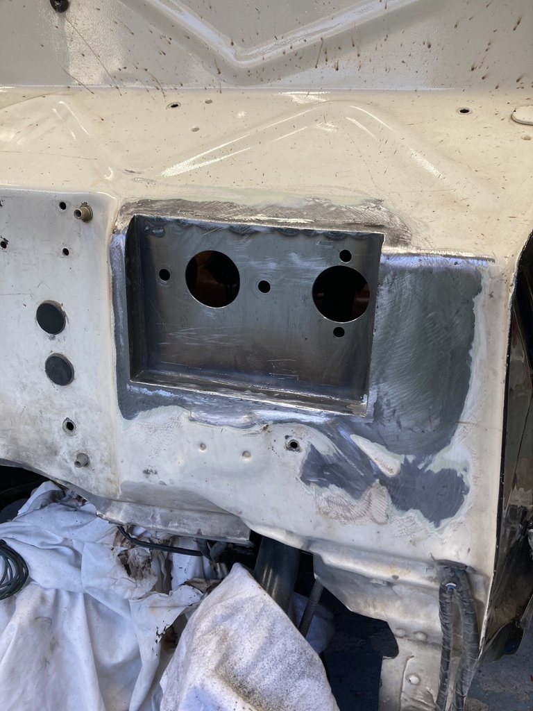 |
| |
|
|
Enbloc
Part of things
 
Posts: 399
|
|
Feb 27, 2023 18:00:21 GMT
|
|
When I started the rebuild at the end of October I put up a list of “To do” jobs.
This is where I currently stand.
Brakes - Partially complete. I still need to order the new master cylinder but when I do it will bolt straight up.
The discovering of the poor pedal ratio means I’m even more hopeful of a better pedal feel.
The brakes will need to be partially replumbed from the new master.
Fumes - ✅ The discovery of the blown out inlet gasket puts that one to bed.
Clutch - Partially complete. I should be able to reuse the old clutch master.
Internal slave needs ordering and setting up. Setting up needs the flywheel change completed.
Flywheel - Just dug out my steel flywheel. Hopefully I can find and match up to the previous balance marks.
Changing it over is easier said than done.
Pedal box - ✅ Done
Gearbox - ✅ Done
Rust & Chassis repairs - ✅ well and truly done.
Steering box - ✅ wasn’t on the original list but done.
New jobs to be added.
Repaint firewall
Fuel system - I need to start again with the fuel system and convert over to a high pressure setup. I’m trying to avoid multiple pumps and swirl pots. A Holley retrofit in-tank pump is appealing and solves multiple issues but they are bloody expensive.
|
| |
|
|
Enbloc
Part of things
 
Posts: 399
|
|
|
|
Just like buses, another steering box appears. This is my dad’s from his ‘48 Pontiac. It’s getting an electric power steering conversion but while it’s out I’m going through it as it was leaking and had noticeable play in the sector shaft. 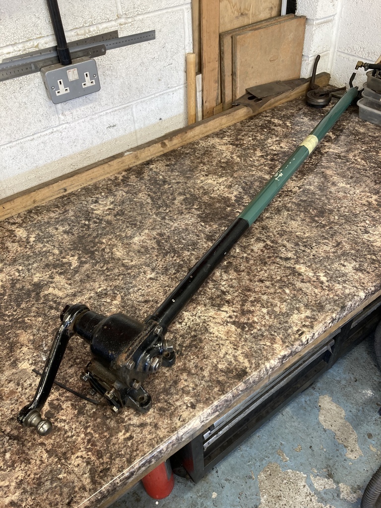 The basic design and function is the same as the Ford but with some detail differences being a GM product. One of the differences is the worm bearing pre-load is set with a screw adjuster rather than the paper shims of the Ford. 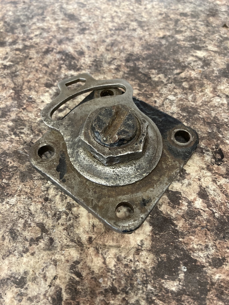 The adjuster was seized and the slot had been chewed up over the years. 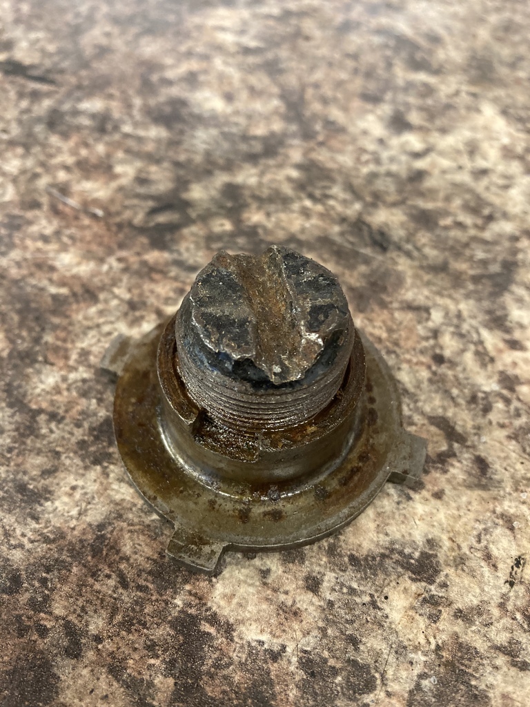 There wasn’t really anything to hold onto with either the screw or the threaded housing, so a plan B was formed. 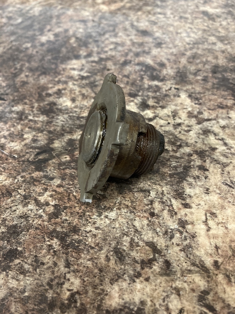 The first piece to go was the damaged slot. I’m not a fan of large slots. I think in this case it was only specified to stop heavy handed mechanics overnighting the bearings. The four pointed housing sat perfect in the 4 jaw so I could face it off. 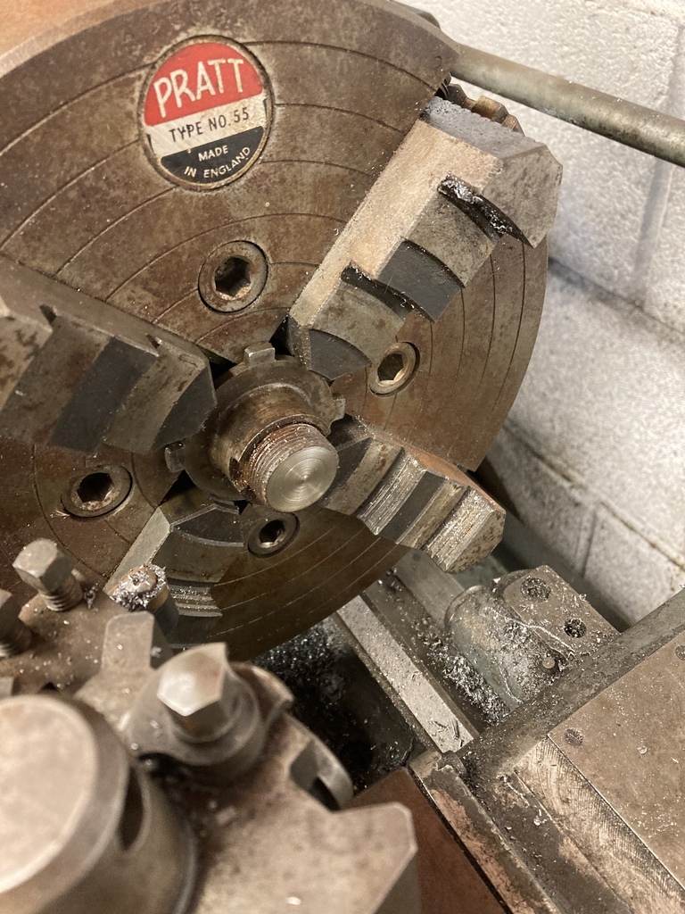 A 7/16 plain nut was a good fit on the the end of the adjuster. This got double nutted on a bolt so it could be ground down to loose some of its height. 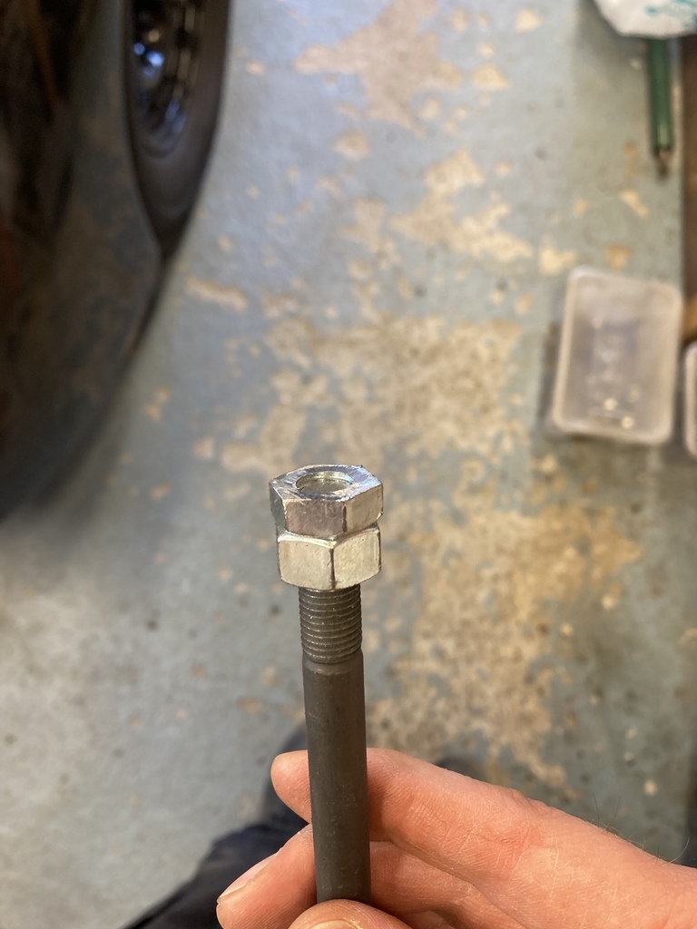 Using a piece of scrap wood I created a stepped hole with a blade bit and normal drill bit. 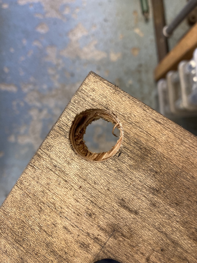 This located the nut centre to the adjuster for welding. 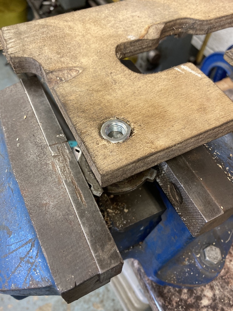 Welding the nut to the adjuster would hopefully put enough heat into it to hopefully break it free. Putting the adjuster back in the 4 jaw after welding held it without damage to break it free. Which it finally did. 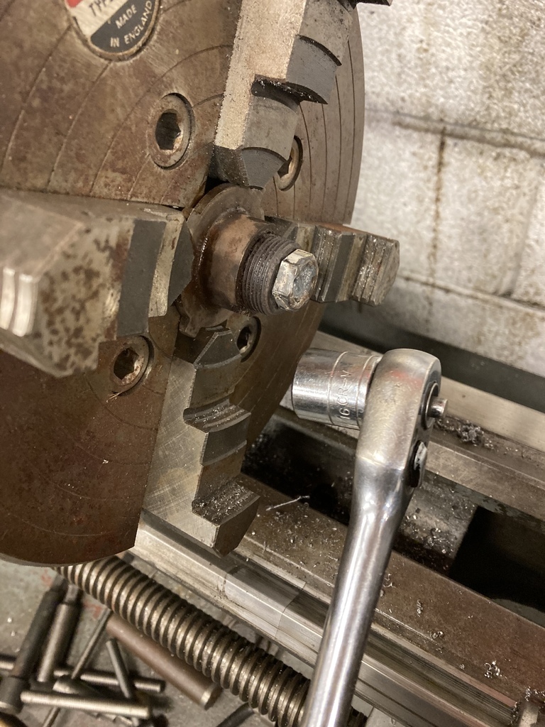 Cleaned up. 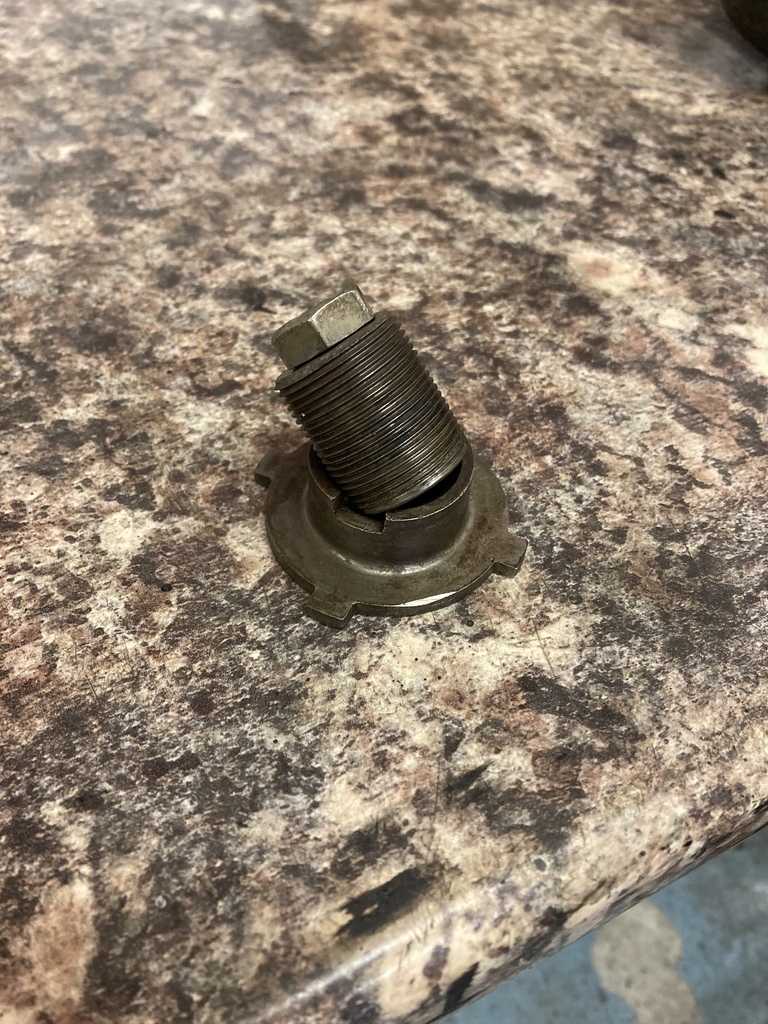 With the worm adjuster fixed disassembly could continue. The sector cover plate off. 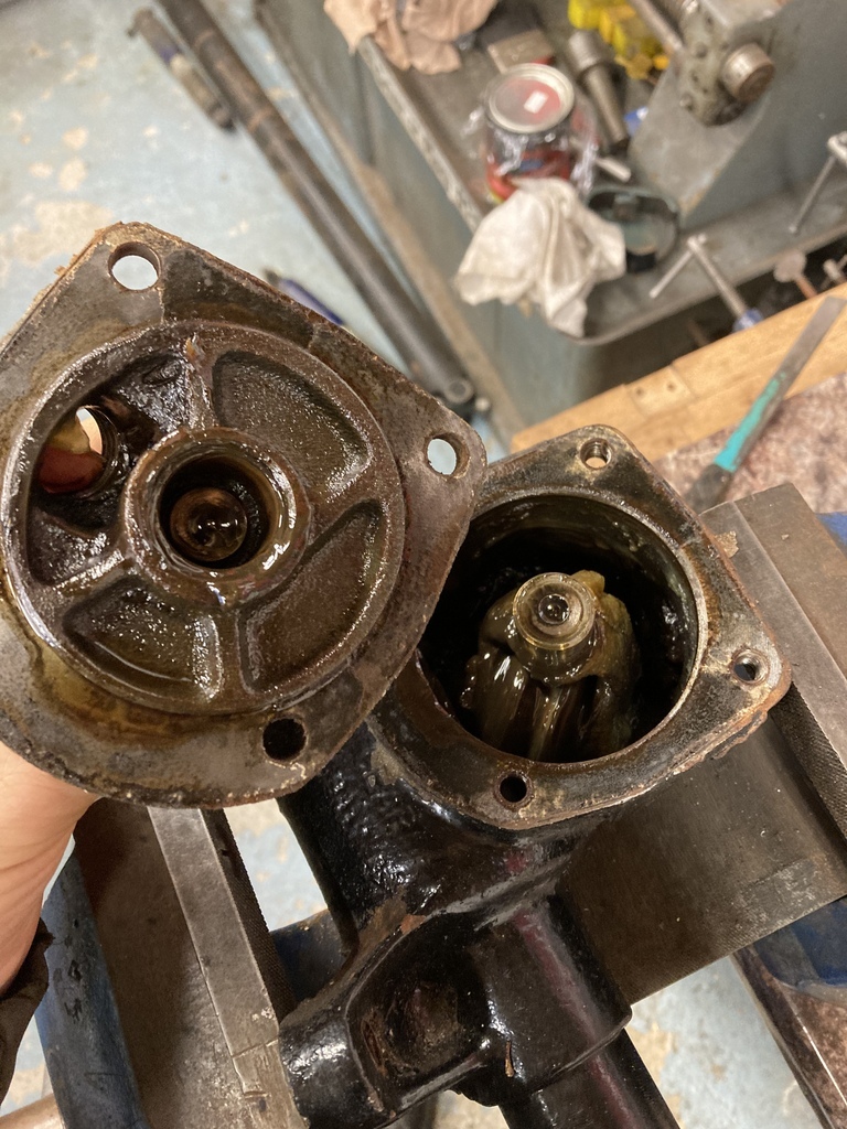 Arrg.. Grease. You don’t put grease in steering boxes! 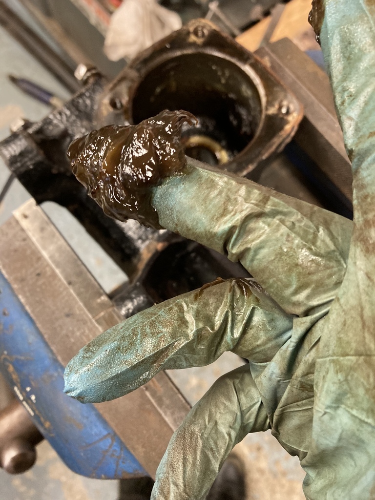 The worm bearings are held in a separate cage inside the case. 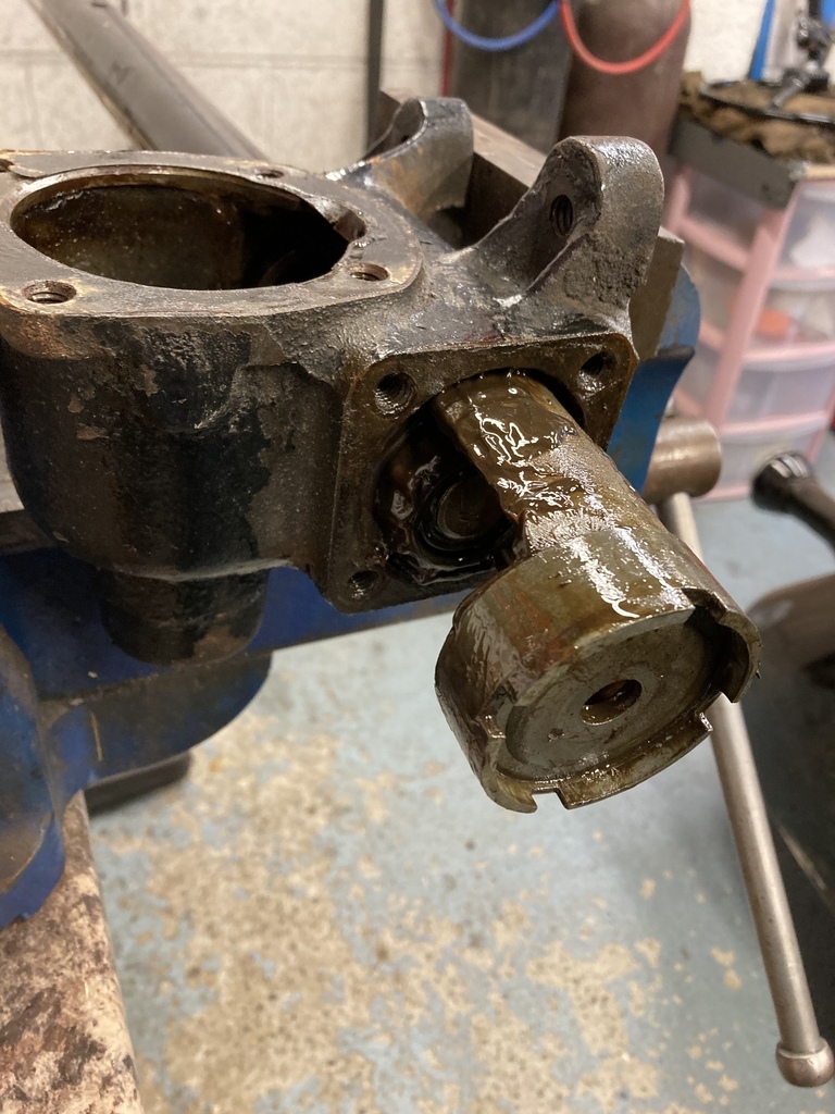 Everything cleaned up. I’ve skipped through a lot as it’s the same as the Ford box. Overall I’d say the Pontiac box is much better quality but it was spec’d for a larger car. 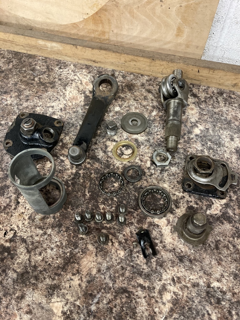 The source of the leak. The sector seal, which is the exact same seal as the Ford, had been pounded flat through a combination of old age and the sector shaft flopping around in the worn bush. 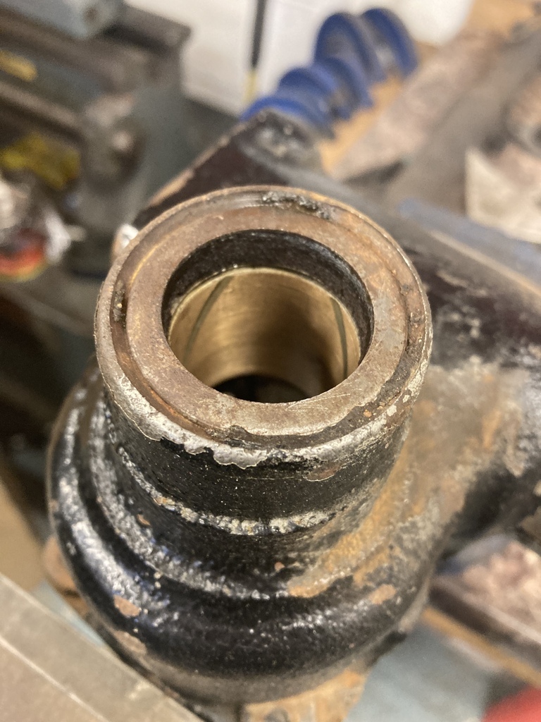 And that’s where it has ground to a halt. Early Pontiac parts are considerably harder to source than Early Ford! |
| |
|
|
Enbloc
Part of things
 
Posts: 399
|
|
Mar 25, 2023 22:58:05 GMT
|
March has been mostly a non-starter. The cold snap stopped any hope of painting the firewall, finishing off the house extension continues to drag on, BMX training is ramping up for the coming race season and it was also my daughters 1st birthday. Another distraction was my dad asked me if I wanted to go half’s on a stall at the NSRA Swapmeet. I thought sure, I could rummage up a few things to sell… Of course a few things turned into a week and half long marathon of emptying and sorting 2 lockup garages, 2 lofts, my garage and my dads workshop! The effort was well worth it as a load of storage was freed up and I had earned enough to pay for the next parts order. But the distractions didn’t stop there. I was asked to help clear a deceased neighbour’s workshop which got me a load of engineering equipment from sets of parallels to faceplates and hand tools and a lot of material stock. This was only part of it and which now means I need a storage solution for it all. 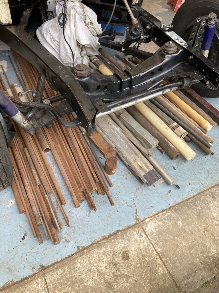 Back to the car I mentioned earlier that I needed to reroute the wire loom from the fuse box as it now sat like this with the new pedal box. 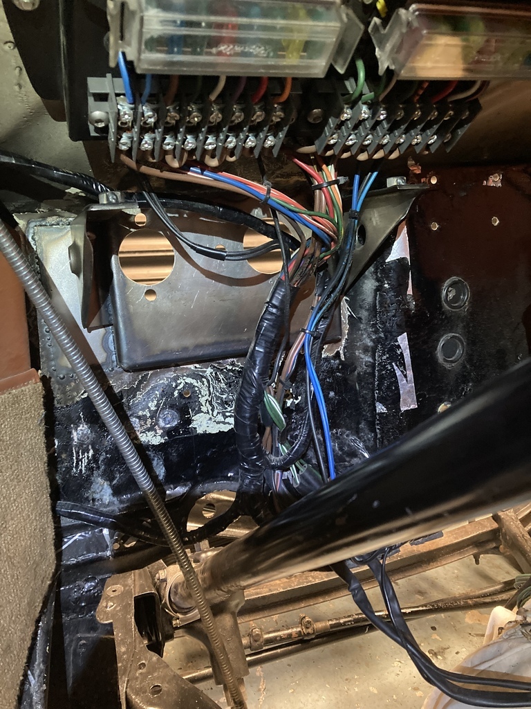 A little examination gave me the confidence that I could split the branches and reroute them either side of the pedal box. The loom wrap was removed from the first section. Most of the wires could be unplugged from the back of the fuse box and moved over. 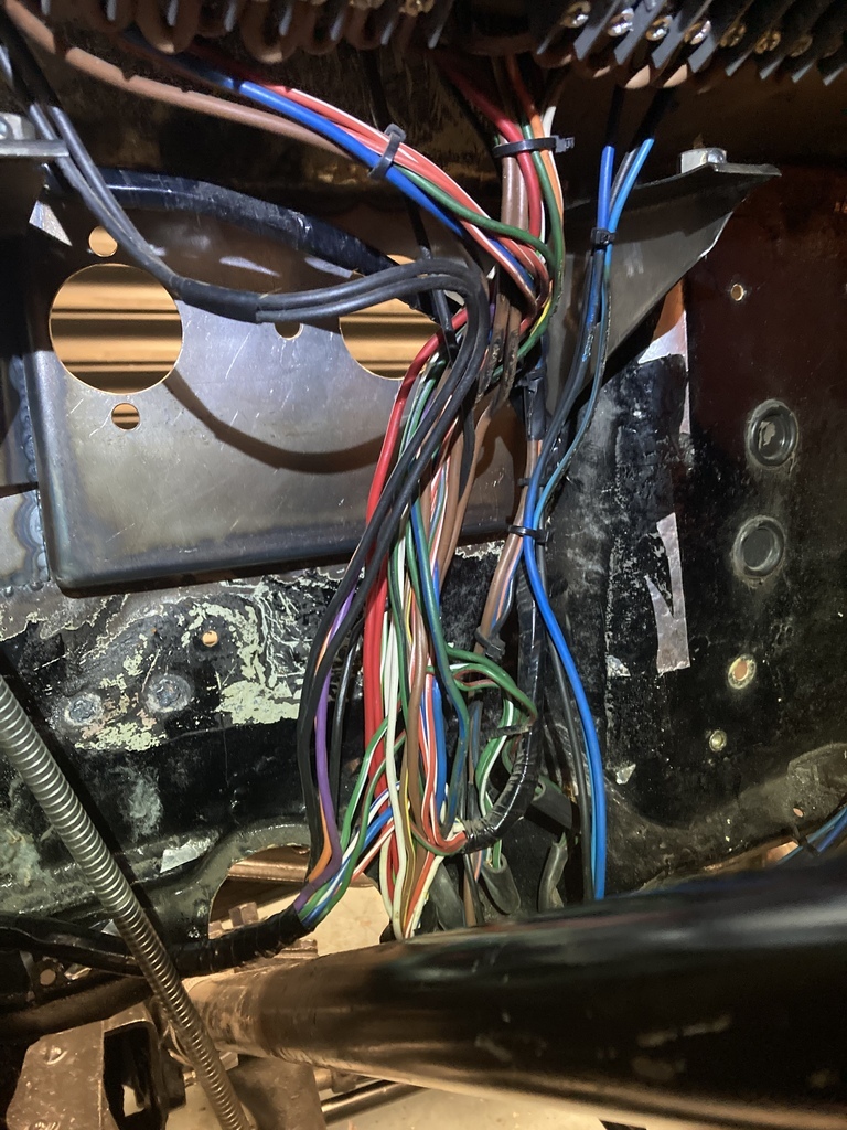 One wire I had to cut a spade terminal off at the back of fuse box to release the wire and crimp a new one on after the wire had been moved and two wires for the indicators had to be extended. These were soldered and shrink wrapped with the same colour and gauge wire as what was used when the loom was made. 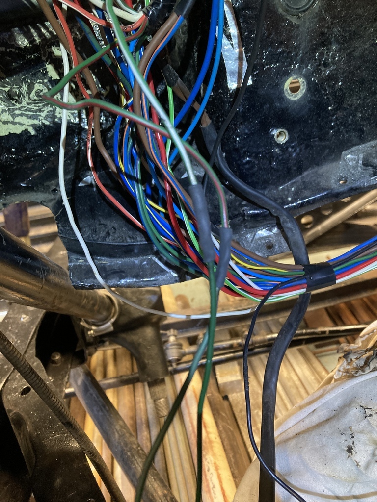 The last one to be dealt with was a pig, the main beam warning light wire. It did this weird loop in the loom from one branch to another which had locked it into place. The only option was to chase it all the way back to the dashboard. More loom wrap removal. 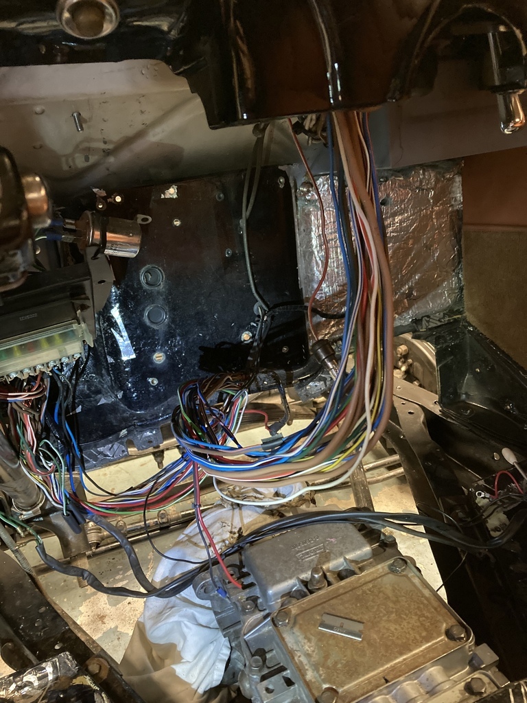 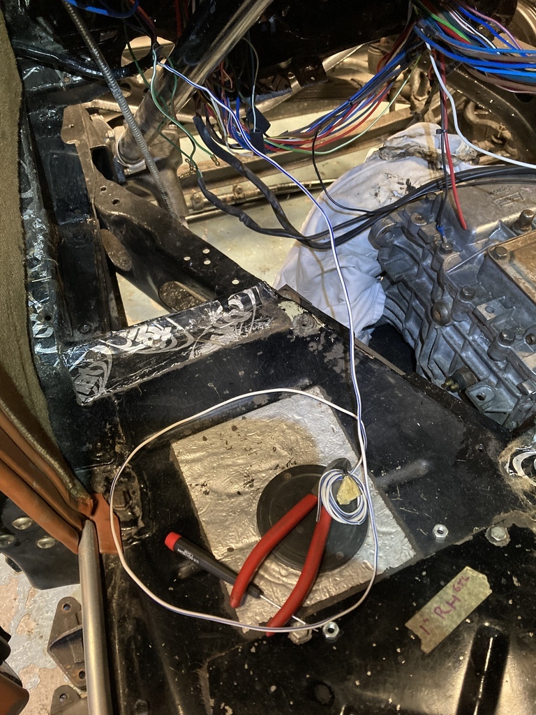 With everything moved it could be bound back up. That will work. 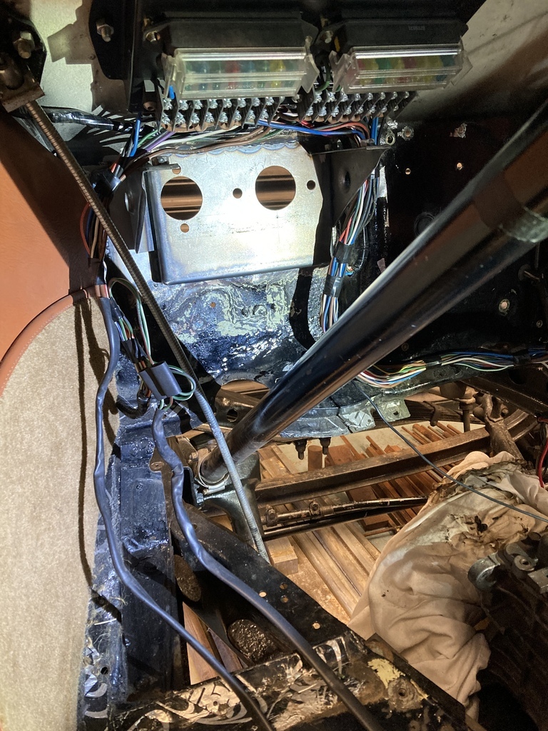 And rebound with new loom wrap. 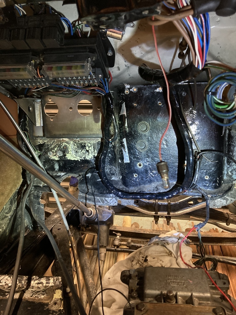 I mentioned in an earlier post about wanting to upgrade the front anti-roll bar. Not having any luck having a custom one made I started looking at factory bars that could be adaptable. At some point I came across a Sierra front bar what I thought might work. I managed to borrow one from a friend to try and I think it might just work with a little modification. Also, they come in 24, 26 and 28mm bars from the factory which is the exact size range I was looking for. 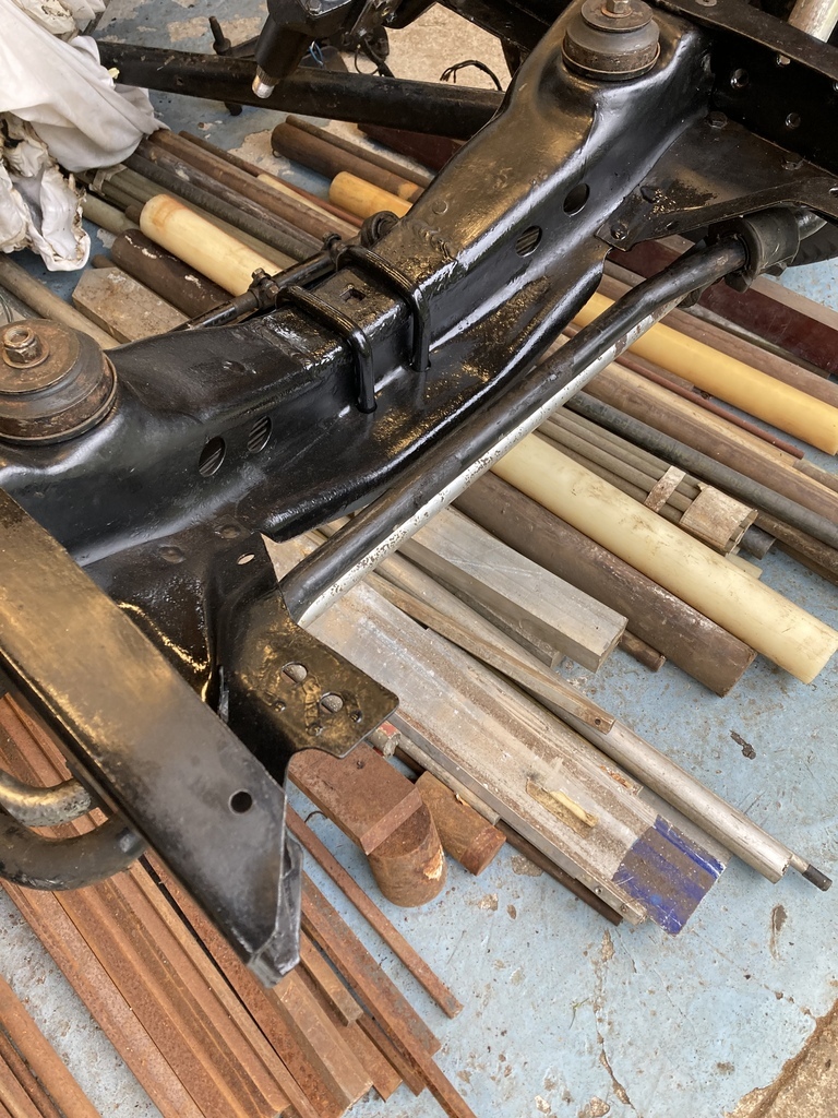 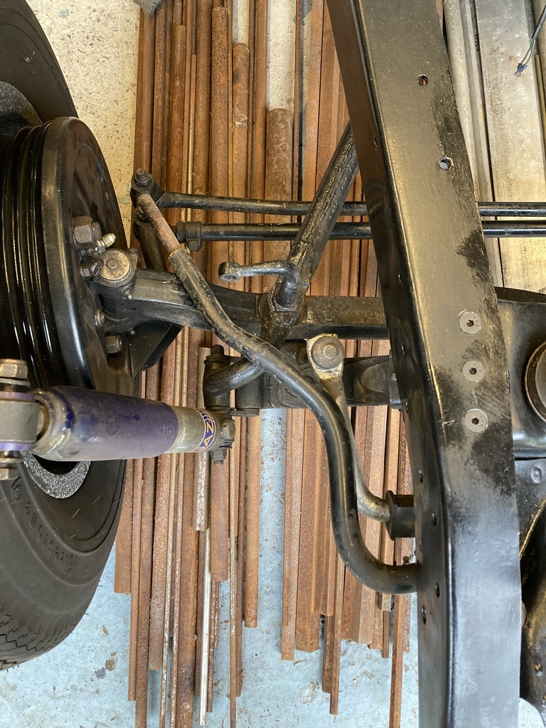 |
| |
|
|
Enbloc
Part of things
 
Posts: 399
|
|
Mar 26, 2023 15:24:09 GMT
|
Continuing the theme of doing everything but work on the ‘36 I was roped into getting my uncles Willys CJ2A Jeep running again as it had a suspected ignition failure. 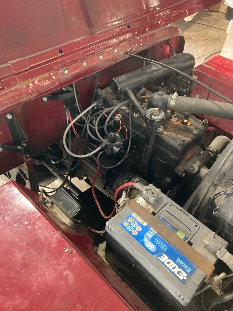 The points and condenser were binned in favour of a Pertronix kit, an easy job. But of course, it wasn’t! After setting TDC through the tiny inspection hole on the bellhousing as all the timing marks are on the flywheel. The dizzy rotor keep falling between two terminals on the cap which is were it had been before removal. The problem with this position was that there was limited movement due to an oiler that protrudes from the body of the dizzy hitting the engine block and the oiler was also positioned downwards meaning any oil would run away from the the dizzy not towards it. None of this seemed quite right. A little research showed the dizzy had be positioned in one orientation, as so. 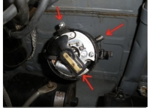 This meant that the offset dizzy drive now didn’t line up with the drive in the block which is actually the end of the oil pump which in turn is driven off the cam. 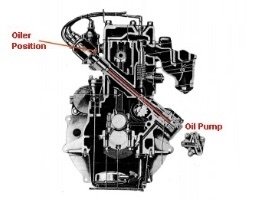 This means the oil pump has to be removed to clock the drive in the correct position for the the dizzy. 😵💫 Luckily the oil pump is externally mounted on the opposite side of the block. 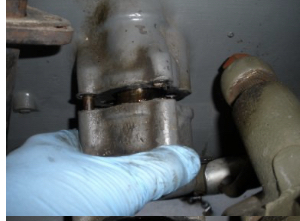 Repeat this process at least twice for the twist of the helical gears throwing off your positioning! I managed a short opportunity to scuff and spray bomb the steering mast in preparation for being refitted. 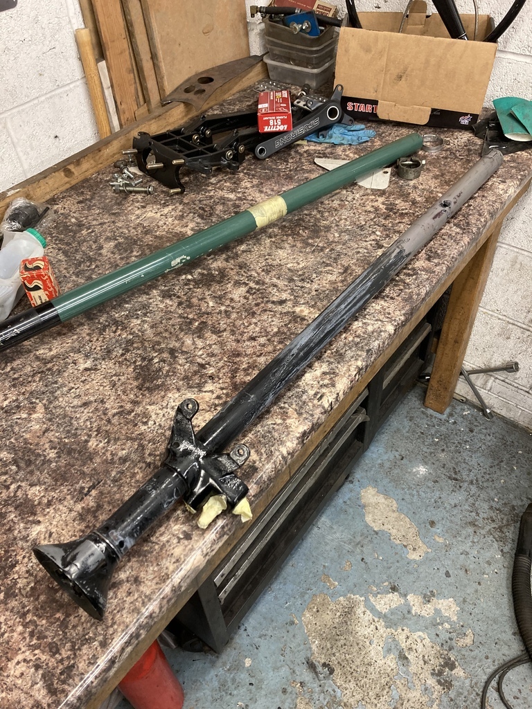 The replacement steering bush arrived for my dads Pontiac steering box. A wallet friendly $16 got a NOS replacement, which was nice. 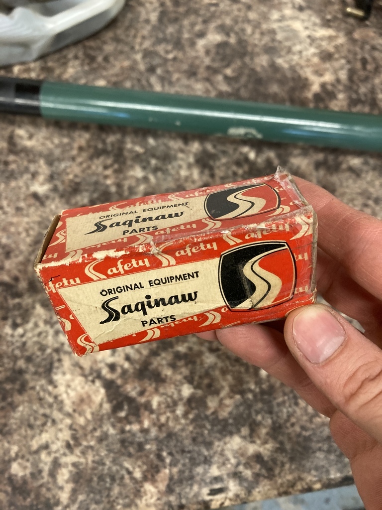 Now to remove a thin wall bush from the housing and replace said bush without completely destroying it. A little time on the lathe, using an offcut from the material I had just collected. 😁 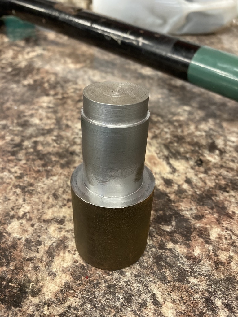 Old bush out. 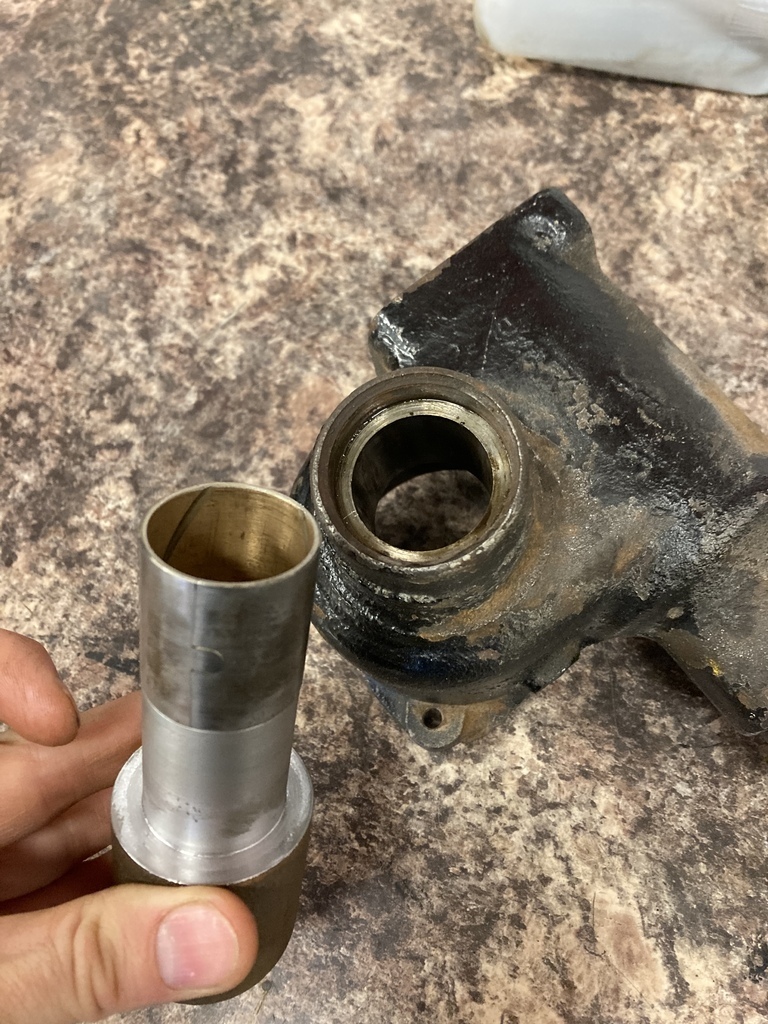 New bush in. 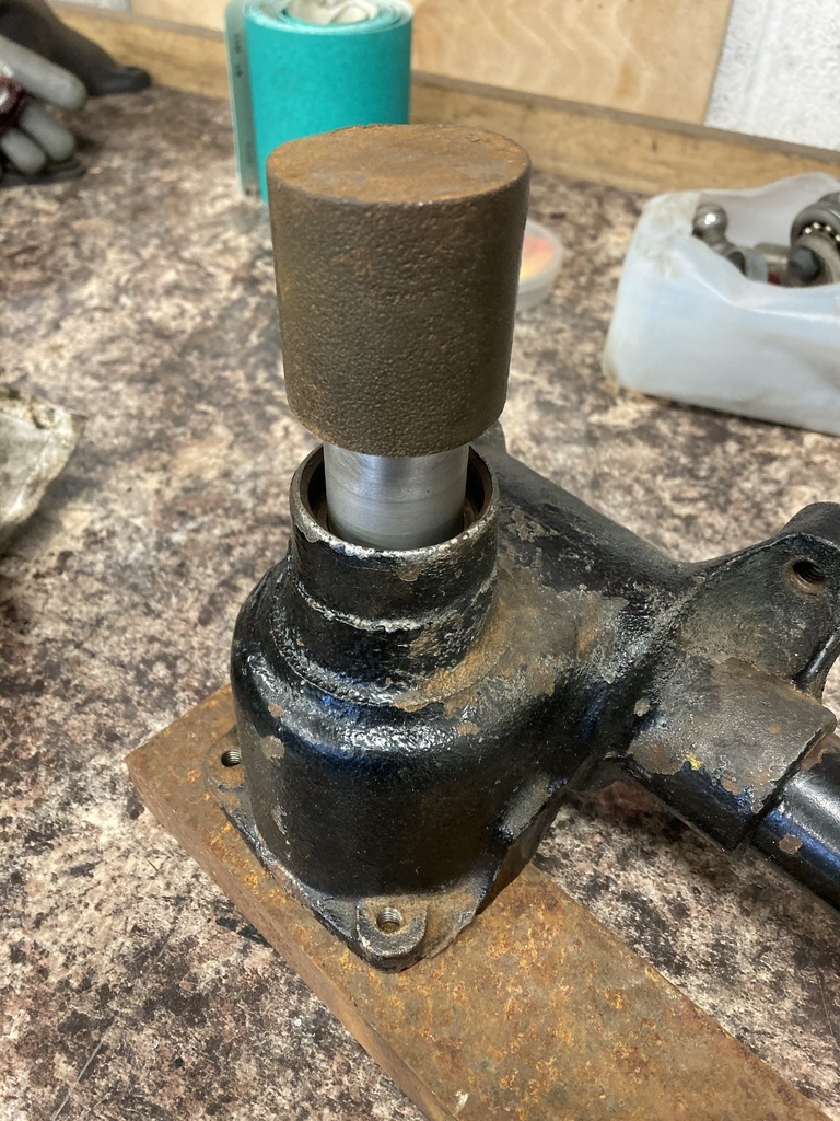 If anyone needs a sector bush tool for your ‘38-75 GM Saginaw steering box, I’m your man. The steering box could now go back together. Two fresh gaskets. 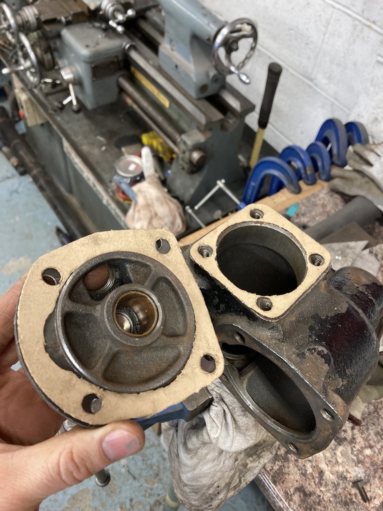 The bottom plate has this thick gasket washer thing that sits in a recess. Unfortunately it broke as it had gone brittle. I think an O-ring may be a good modern alternative? 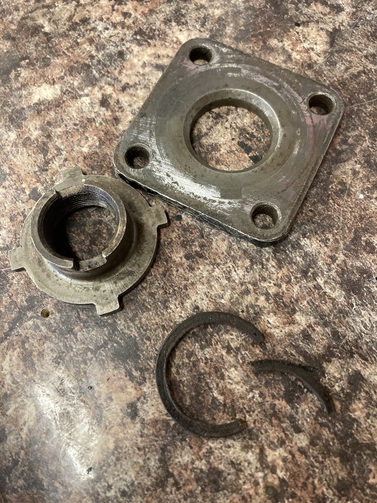 The worm and steering shaft with that weird cage around it. The end plate has a slot in it which locks into that cage and rotates it. At this point I wasn’t really sure of the why’s. 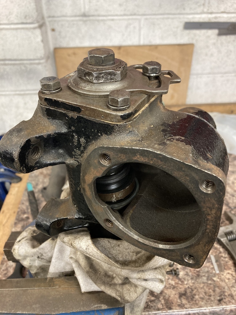 Sector shaft in with end plate, then it all became clear. 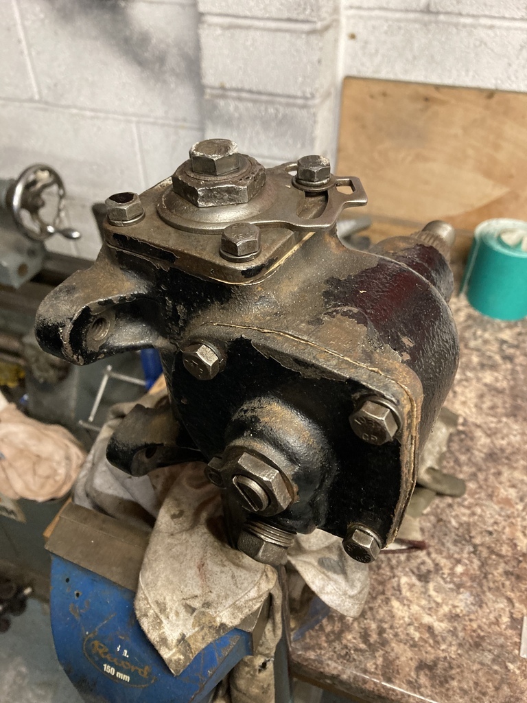 There are 3 points of adjustment, not 2 as first thought. There is the screw adjuster for the worm bearing preload, a screw adjuster for the sector end float and then the slotted plate adjuster which rotates the cage inside the box. This, I now realise, adjusts the engagement of the worm and sector teeth. I guess the cage must be on a concentric to move the worm in and out of tooth engagement. |
| |
Last Edit: Mar 26, 2023 15:29:05 GMT by Enbloc
|
|
Enbloc
Part of things
 
Posts: 399
|
|
Mar 28, 2023 20:41:48 GMT
|
I had the opportunity of a decent day in the garage so I went for job that I could complete for a mojo boost. I chose to tackle the front shock brackets. These are the said brackets. They are a telescopic conversion from Pete & Jakes. They were once solid but I went at them with a hole saw some time ago. 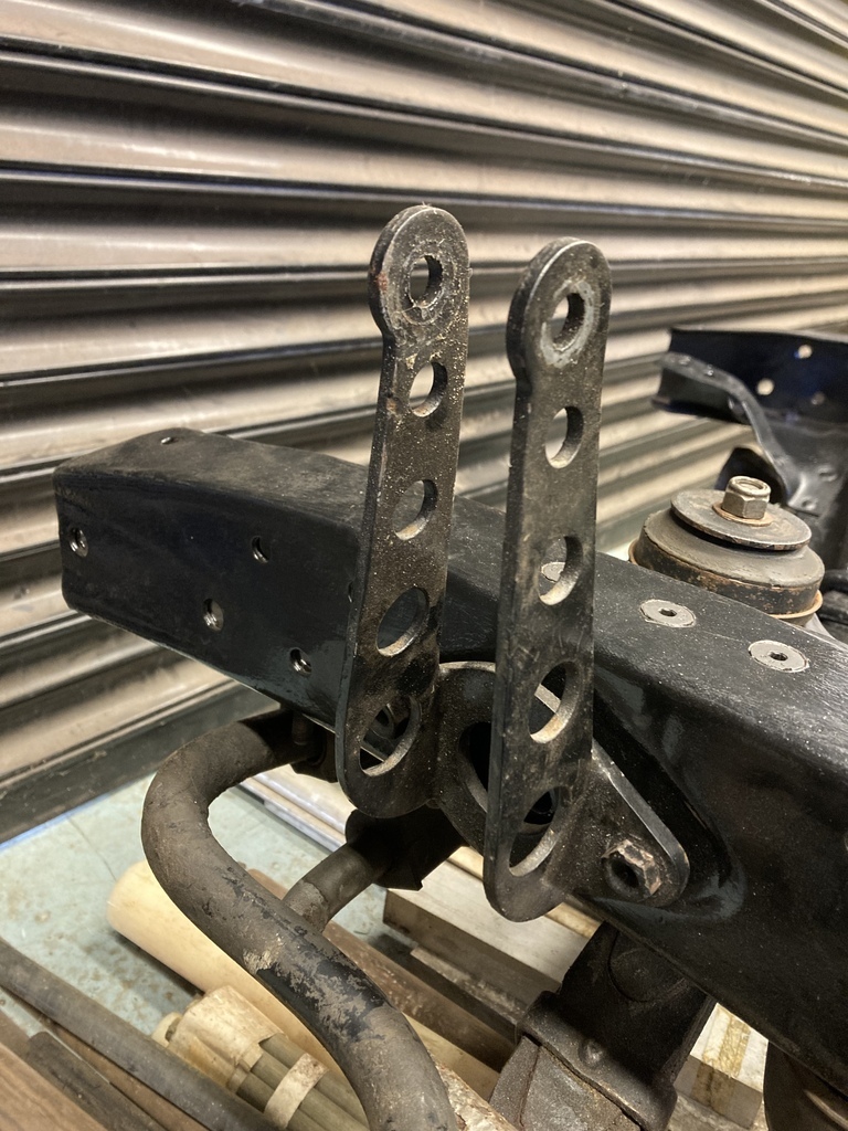 They have a problem. They are designed to take a coverless Hot Rod style shock. When you try to fit a decent shock there becomes clearance issues, as so. 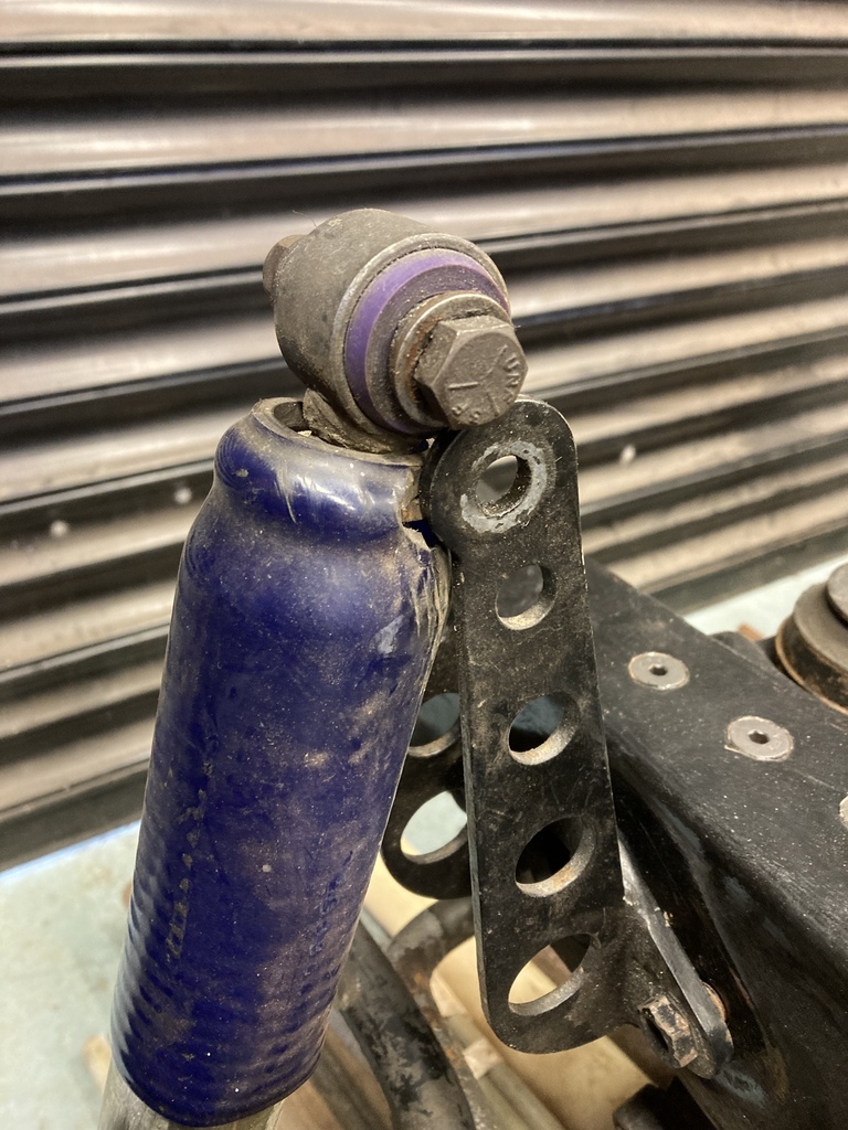 When I originally had them made and I discovered this issue my frustration and haste resulted in this monstrosity. 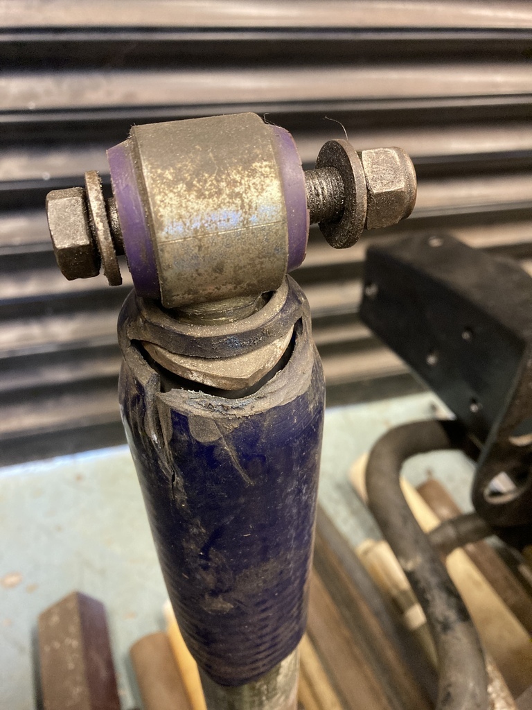 The shocks are getting tired now so I’m looking to replace them for fresh ones but I won’t be doing this again. When I was having a clear out for the Swapmeet I found this old pair of brackets which I forgot I had. 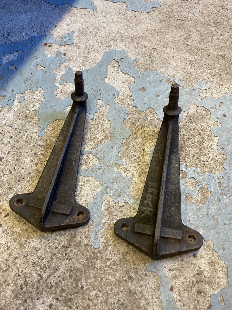 They are Gabriel brand, which is big shock brand in the US and were probably from a period Ford telescopic conversion from the distant past. I thought all my prays had been answered when they bolted straight on even if they did weight a ton! 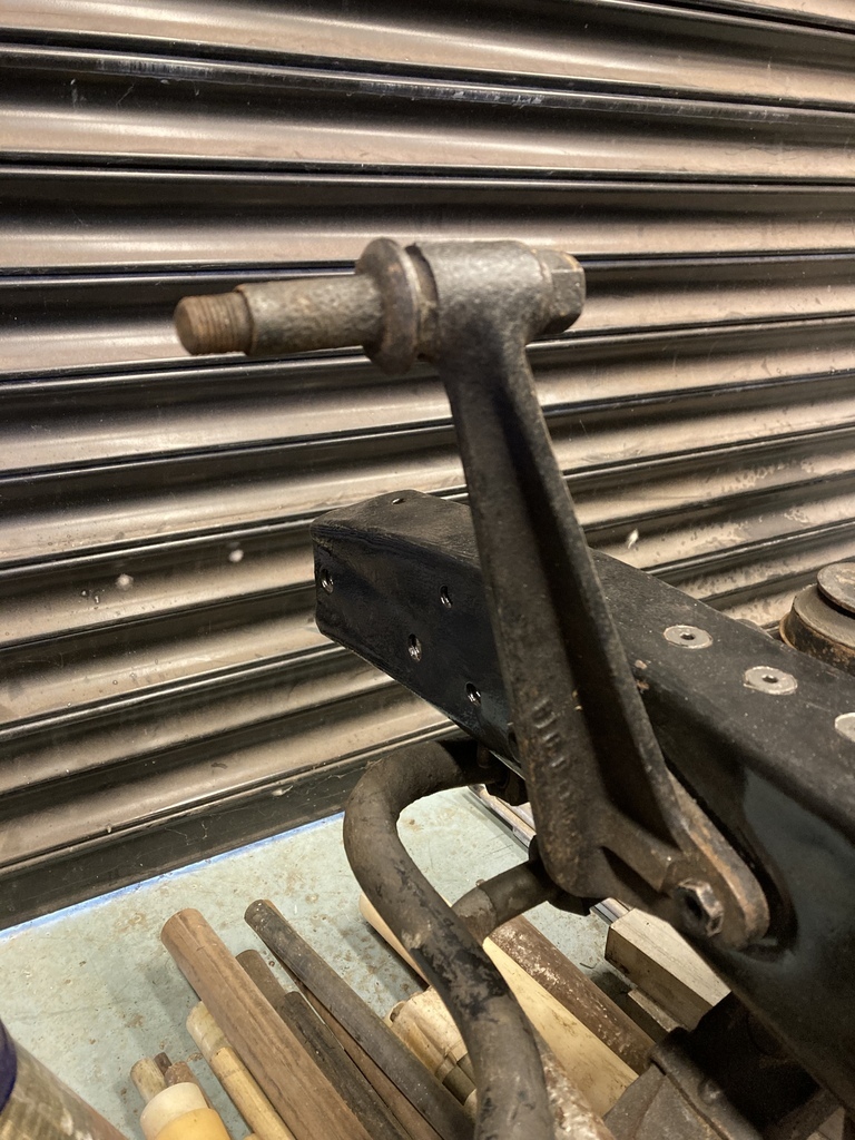 It wasn’t to be as the mounting stud was just slightly off on all angles and positions. 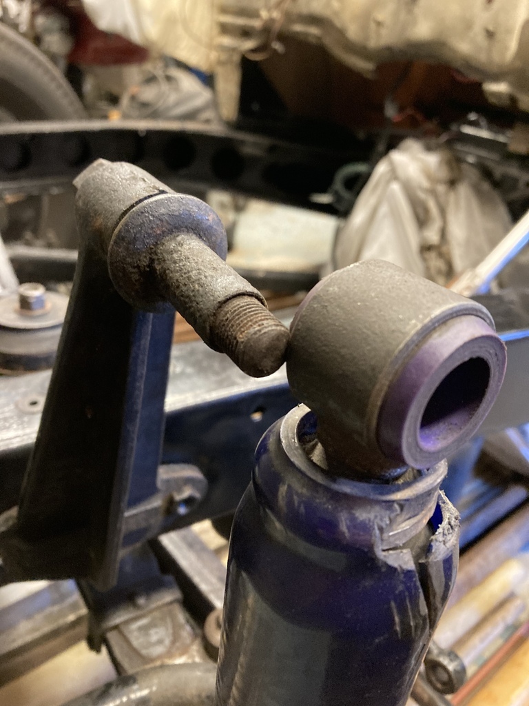 I thought about cutting and welding them but I couldn’t decide if they were cast steel or cast iron. I did the grinding spark test, inconclusive. I even drilled a test hole in the back to see how the swarf formed but still couldn’t make a decision, so gave up on them. 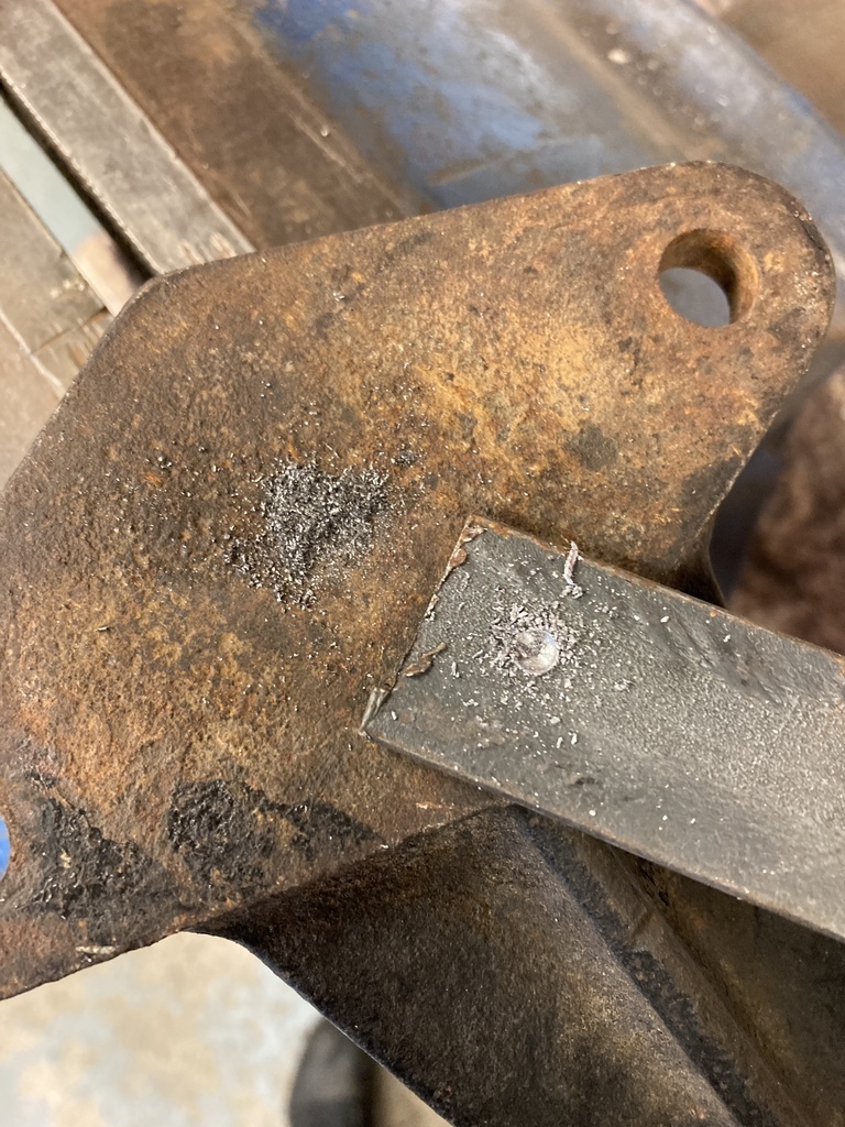 I thought maybe I could use what I all ready had as all was needed to move the top mounting point away from the original to gain the needed clearance. I sketched these extenders. 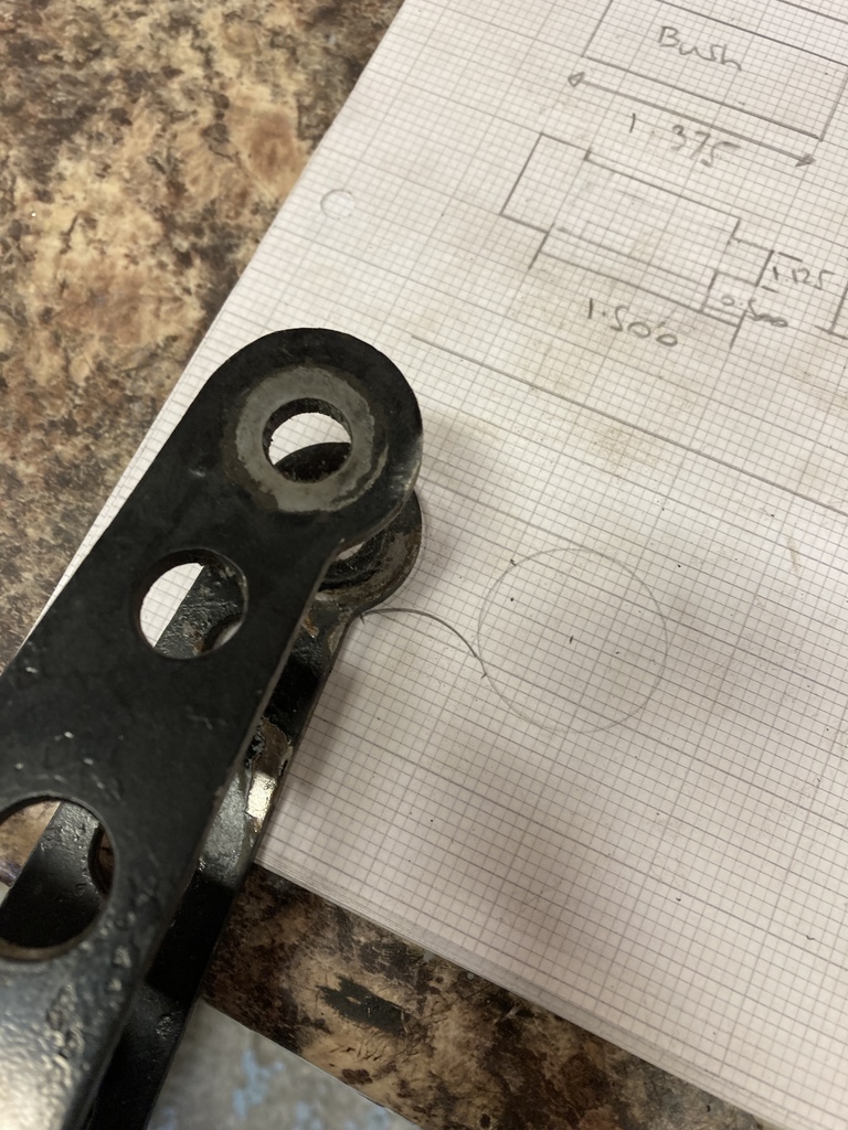 Transferred to card. 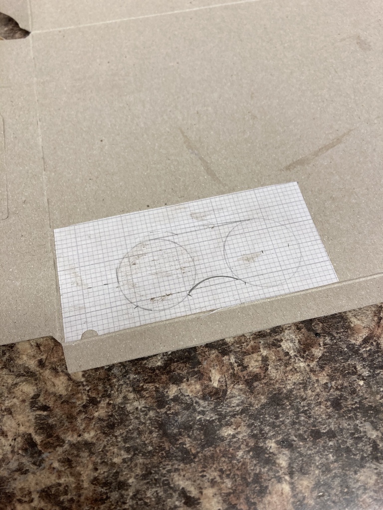 Cut out and marked out on some 5mm plate. 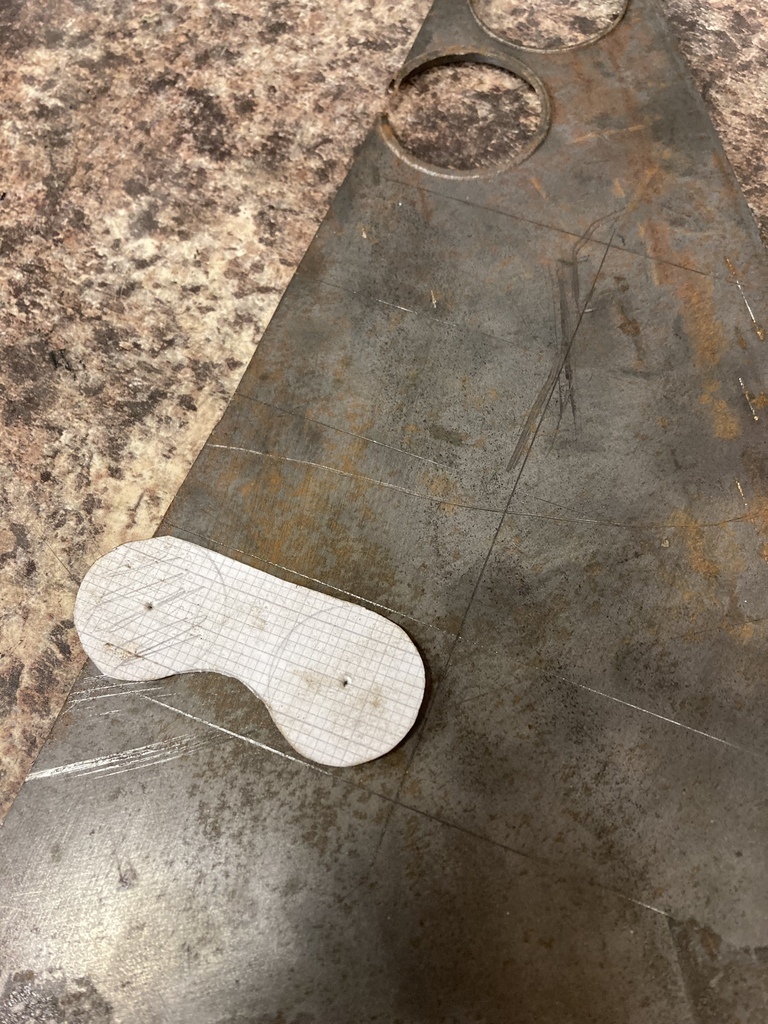 I put the holes in and used a hole-saw for the curved end. It was at this point I started getting cold feet over them mainly because they looked a bit s**t sitting there and even worse on the car. I was so invested at this point I kept going. 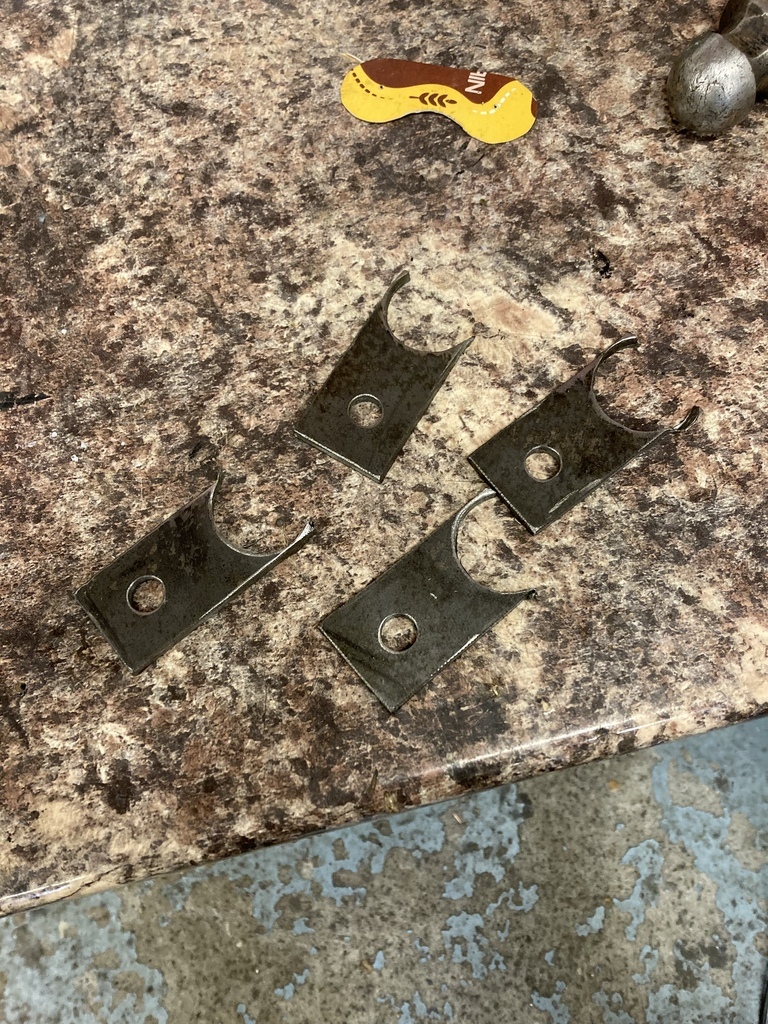 Some shape put in. I deviated at this point to not put the swoop in as it was reducing the contact patch too much. I had another thought, that maybe I was messing with the stresses on the originals by putting in a lever action? I kept moving forward. 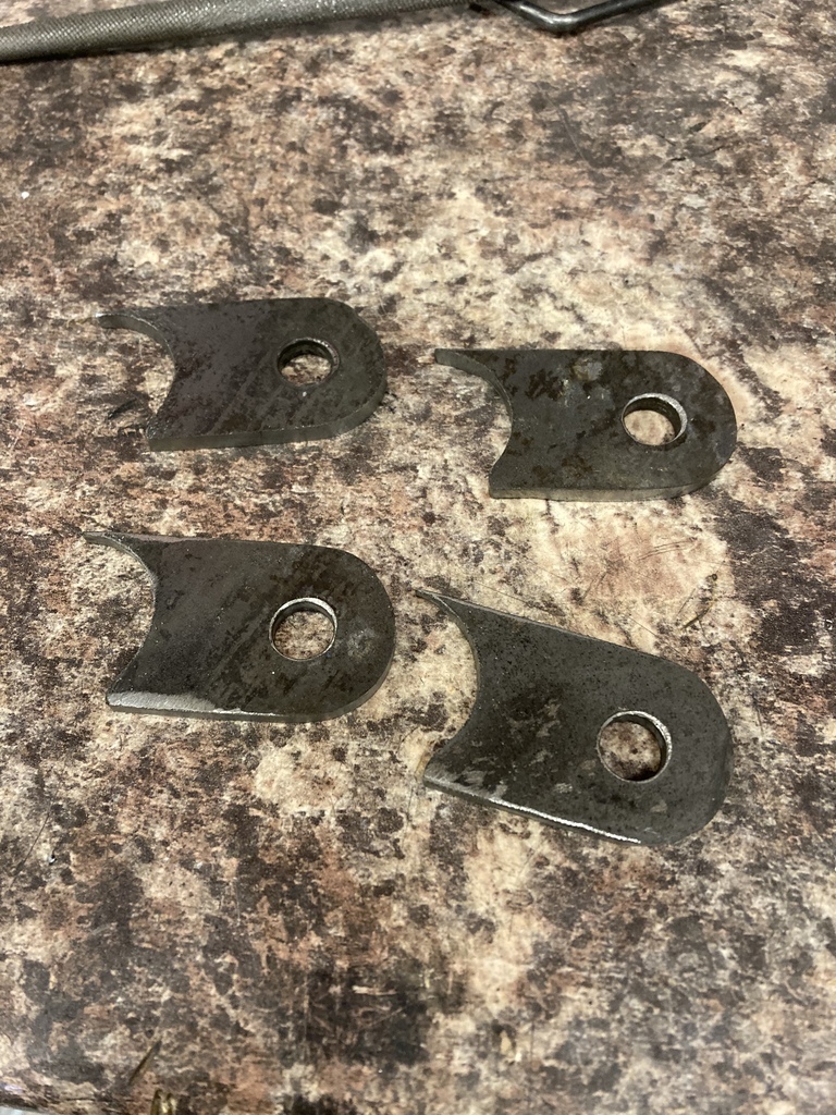 I tacked the extenders in position. They weren’t as terrible as I envisaged but not that great either. Then I tried the bounce test by jumping up and down on the chassis and watched the bracket flex, considerably, from side to side with the suspension movement. 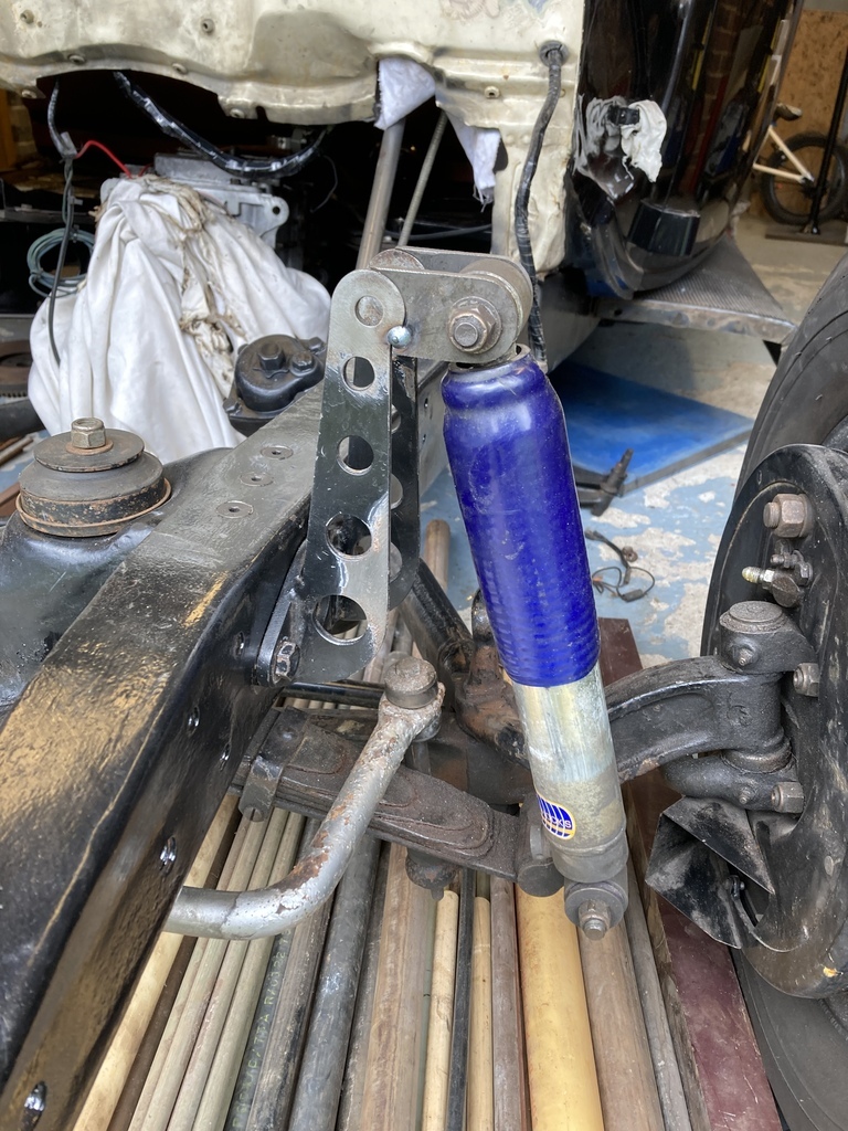 I downed tools and closed the door behind me. |
| |
|
|
mylittletony
Posted a lot
  
Posts: 2,419
Club RR Member Number: 84
|
|
Mar 28, 2023 21:10:10 GMT
|
|
How about a fabricated replica of the Gabriel version with more favourable geometry?
Nice T cross section, with some design flourish?
I would have thought that would be easy enough for a man of your talent?
|
| |
|
|
Enbloc
Part of things
 
Posts: 399
|
|
|
|
How about a fabricated replica of the Gabriel version with more favourable geometry? Nice T cross section, with some design flourish? I would have thought that would be easy enough for a man of your talent? Now the dust has settled I have a plan B! I really need to get the front panels back on first before I go any further as the inner fender panel sits really close to the brackets so will dictate what I can do. |
| |
|
|
|
|
|
|
|
|
|
|
For what it's worth, I think your extender idea could work okay if you boxed in the uprights. Thin 2mm steel with holes in if you like, back, top and as much of the damper side as possible. Plus a generous fillet on underneath the extenders going down the upright.
As an aside, they look like Gaz dampers? If so, Gaz offer a rebuild service, which should save you the full cost of new ones, plus being rebuildable would suggest that those covers must come off. If you, or Gaz, built them back up without the covers and the metal disc that holds the covers in place, would that solve the problem?
If none of that works, my suggestion would be to make up another set of uprights, but further apart, with a longer bolt and spacers either side of the damper eye. With a bit more boxing/bracing you could also make them of much thinner steel. Be sure to include speed holes.
|
| |
|
|
Enbloc
Part of things
 
Posts: 399
|
|
Mar 29, 2023 17:48:18 GMT
|
For what it's worth, I think your extender idea could work okay if you boxed in the uprights. Thin 2mm steel with holes in if you like, back, top and as much of the damper side as possible. Plus a generous fillet on underneath the extenders going down the upright. I thought of boxing the brackets but they seem to be pivoting around the mounting flange at the base. I don’t think boxing would help what is a flawed design. A brace from the back to the top of chassis would solve everything but wouldn’t be achievable in reality as the inner fender panel will be there. As an aside, they look like Gaz dampers? If so, Gaz offer a rebuild service, which should save you the full cost of new ones, plus being rebuildable would suggest that those covers must come off. If you, or Gaz, built them back up without the covers and the metal disc that holds the covers in place, would that solve the problem? They are Gaz. I believe Gaz don’t rebuild these units. They don’t come apart from what I can see and they were only £50 each new but that was a while ago now. If none of that works, my suggestion would be to make up another set of uprights, but further apart, with a longer bolt and spacers either side of the damper eye. With a bit more boxing/bracing you could also make them of much thinner steel. Be sure to include speed holes. Ah, you’ve spoiled the surprise! That is my plan B but as mentioned above I need to have the front panels on to know clearances. |
| |
Last Edit: Mar 29, 2023 17:52:29 GMT by Enbloc
|
|
Enbloc
Part of things
 
Posts: 399
|
|
Mar 31, 2023 19:37:49 GMT
|
That gap in the weather finally appeared so it was full steam ahead on the firewall repaint. I’d actually been dreading this as I detest paint and body prep. Luckily, my dad loves it! I went off to get supplies, he got going on the sanding The last few items were removed and any loom was pulled back through. 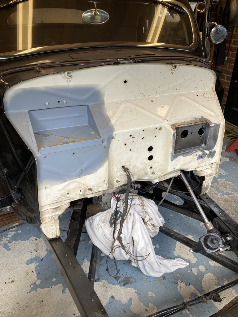 Ready for primer. 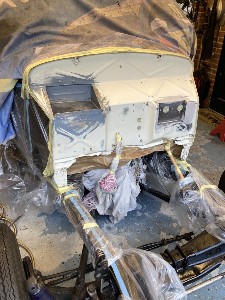 The firewall wasn’t the only area to get paint. This small patch on top of the roof was totally forgotten on the first round of paint last summer. Out of sight, out of mind! 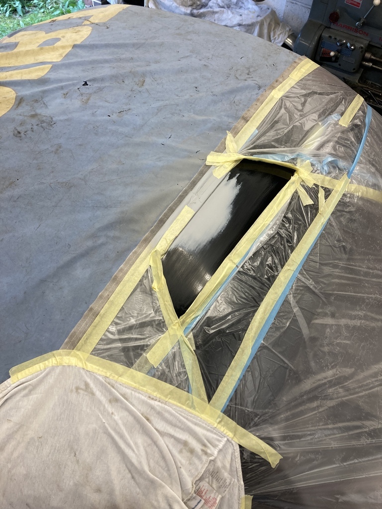 Primed. 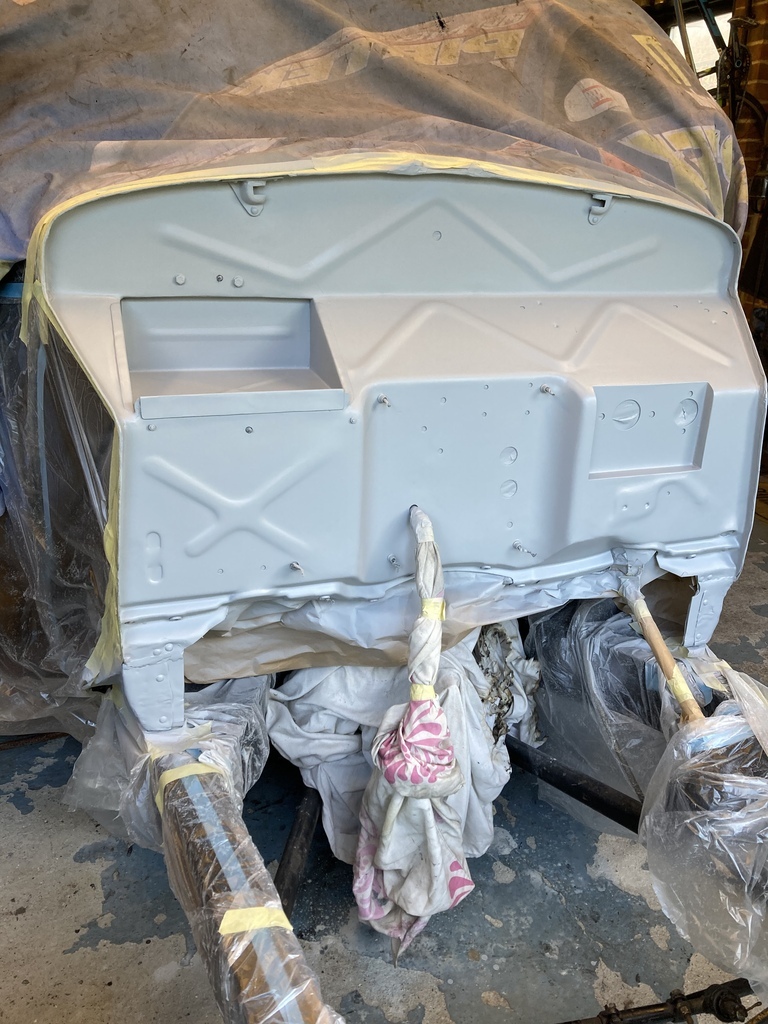 Colour. 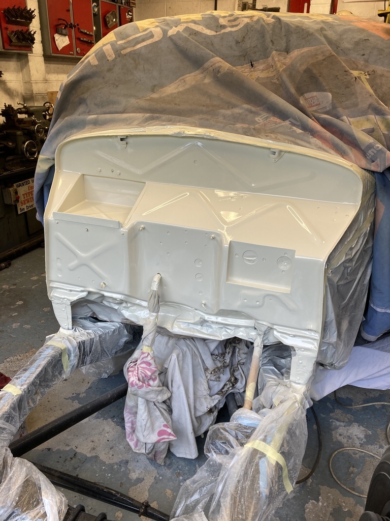 Fresh. So good to have it back in colour after having it patched and tatty for so long. 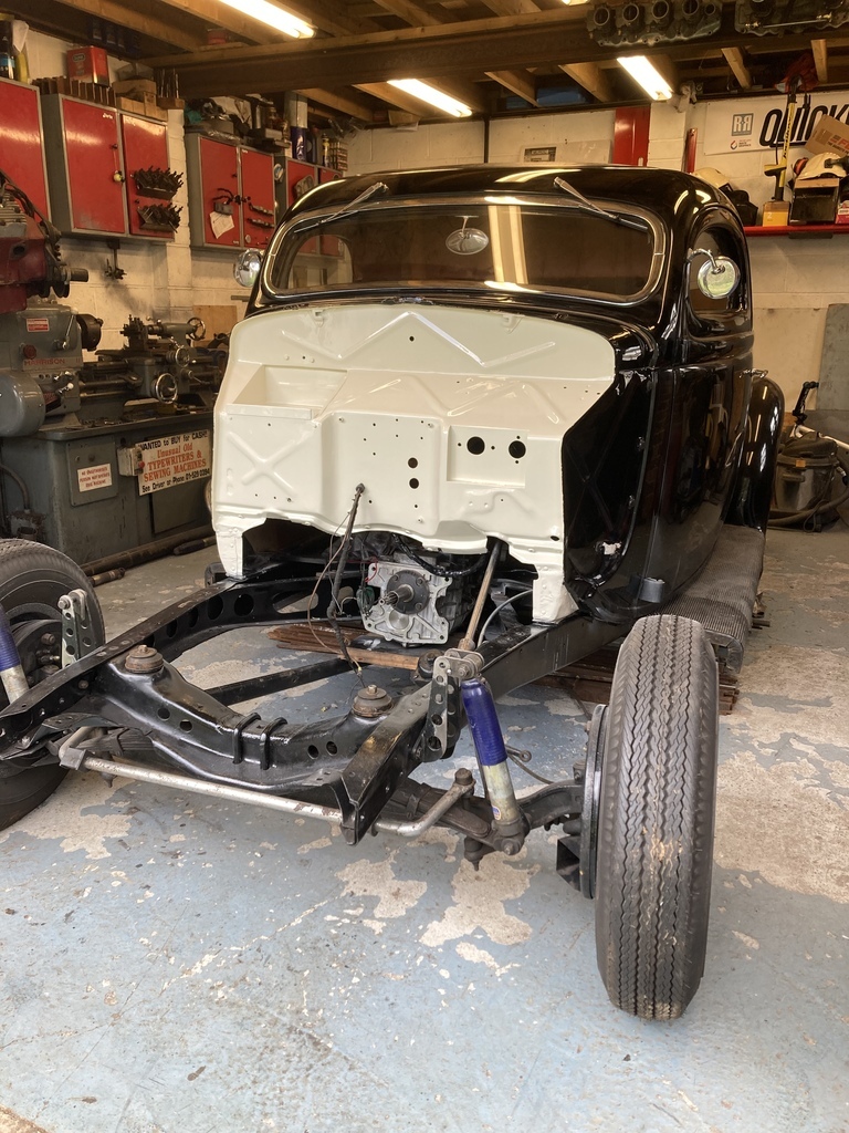 All reassembly from here on out and with this care package from Summit that should be all the big ticket items purchased. 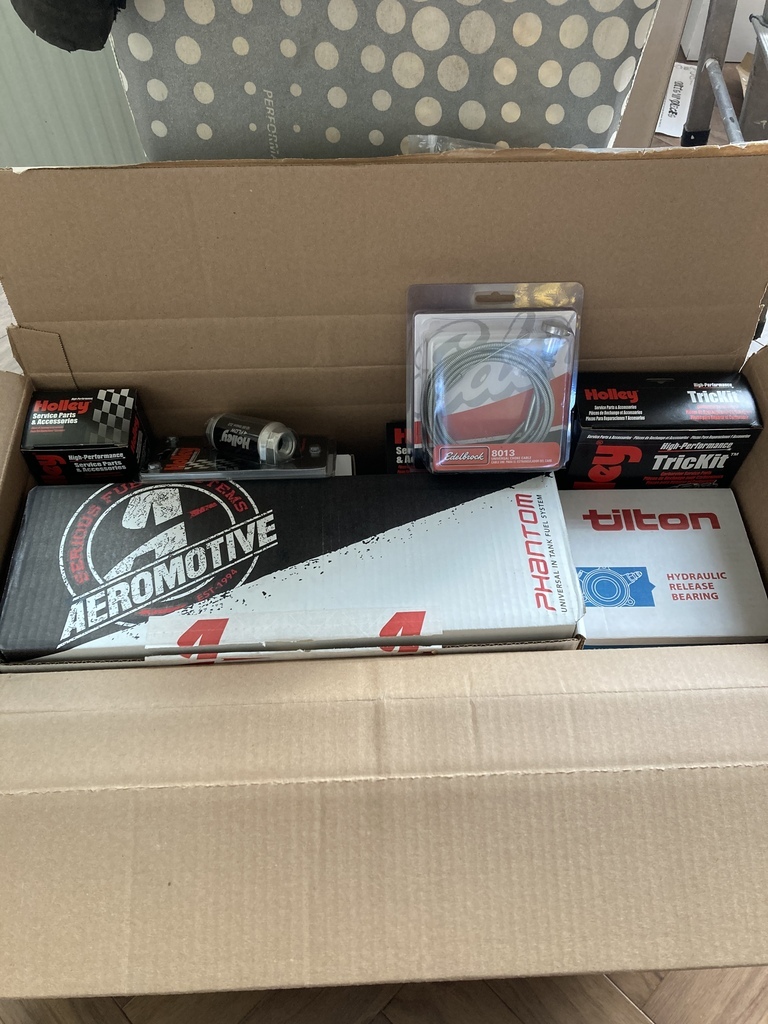 |
| |
|
|
teaboy
Posted a lot
   Make tea, not war.
Posts: 2,125
|
|
Mar 31, 2023 20:27:46 GMT
|
|
Looks excellent, dude.
|
| |
|
|
Enbloc
Part of things
 
Posts: 399
|
|
|
|
Another job I was avoiding was changing the flywheel on the turbo engine. I’d made the decision to use the ally flywheel over the lightened stock flywheel some time ago as covered way back in this thread on the second or was it the third build of the engine! I changed my mind, yet again, because of that final drive of the car last year before I tore it apart. Very frustrating as the engine was already buttoned up by this time and would now have to be cracked open again. Due to the bellhousing being cast integral to the block the sump has to come off to allow the clutch and flywheel to drop out. Joy. This was the replacement pulled from storage. 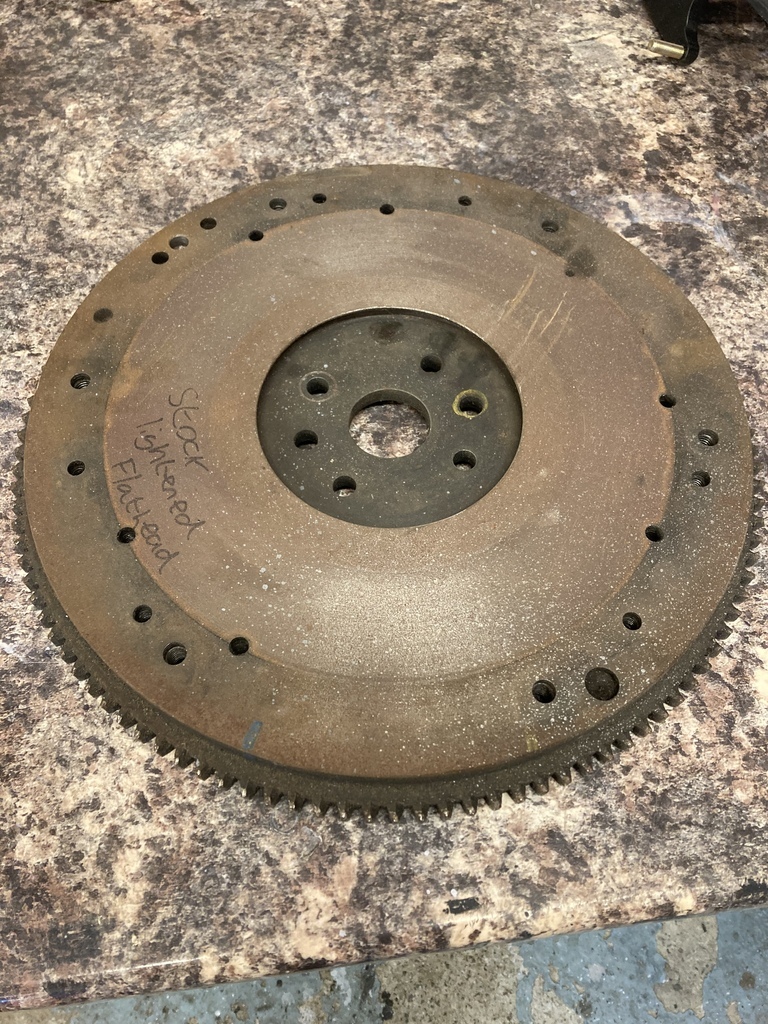 Luckily both flywheels had been balanced to the same rotating assembly and clutch pack. The problem was working out which mark, of the multiples ones, was the correct one. 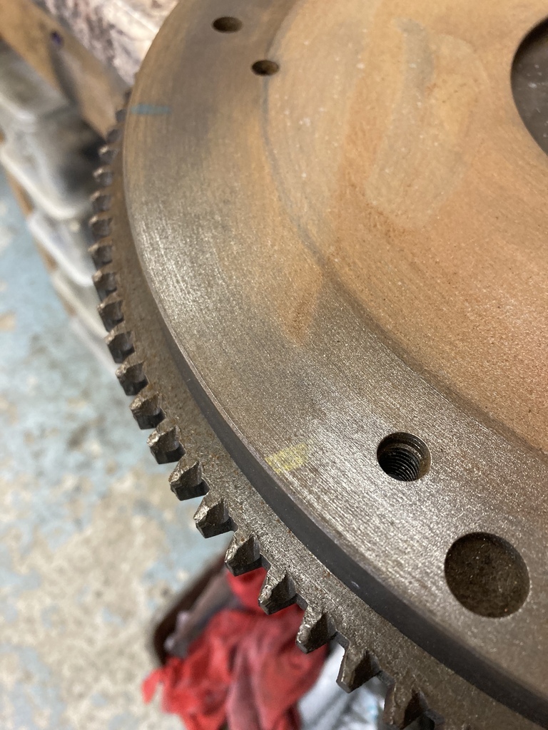 Cleaned up it was surprisingly good, with no wear or marks anywhere. I’ve definitely used this flywheel at some point. When and where, I have no idea. 🤷♂️ If you’re wondering why there are so many holes in the face it’s because it has been drilled for 3 different pressure plates over the years! 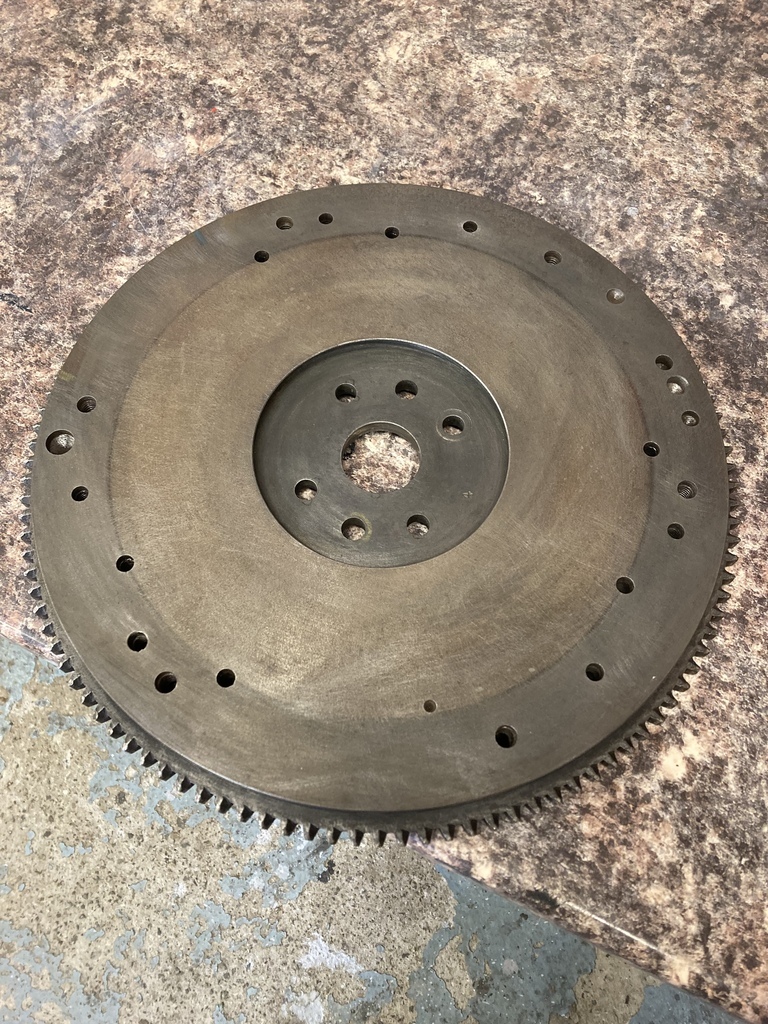 Engine back out. 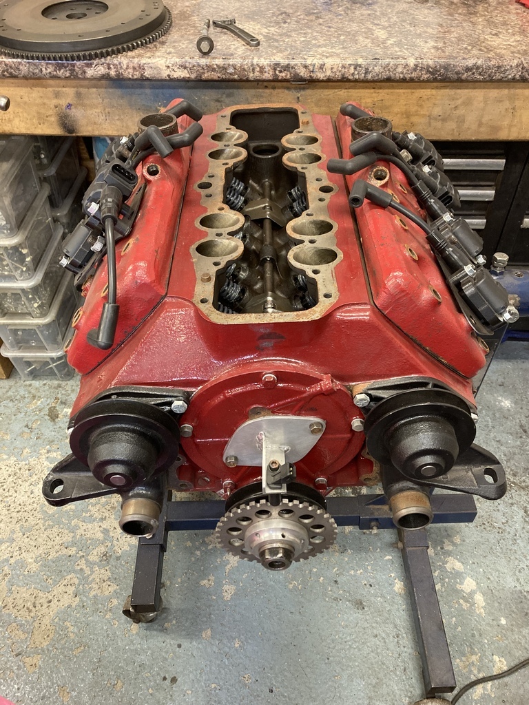 I’d already lined up a new sump gasket in preparation. I had a faint hope that it come off clean. Yeh, that didn’t happen. It was well and truly stuck together. 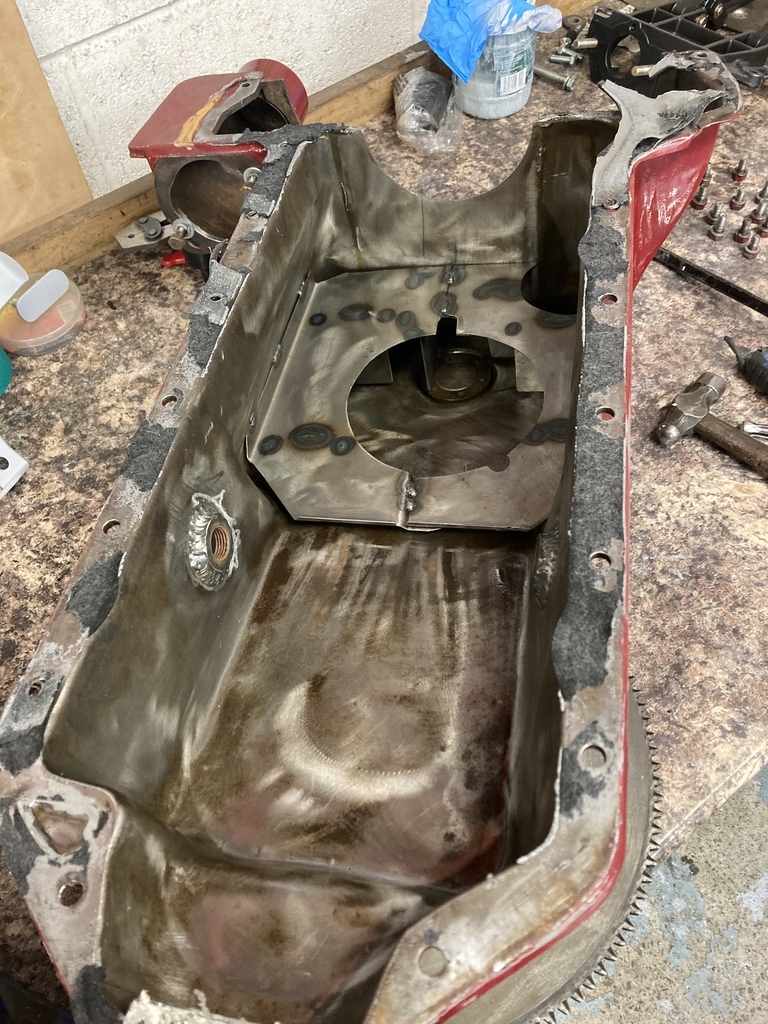 All the old gasket scrapped from the block. It’s all still there! 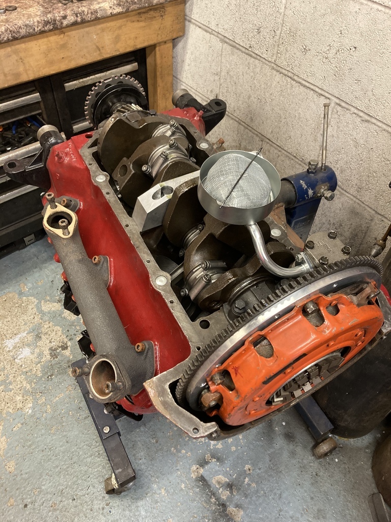 The marks on the pressure plates. There is actually 3 different coloured marks here one over the top of another. The blue one lined up perfect to a blue line on the stock flywheel. We’ll take that then. 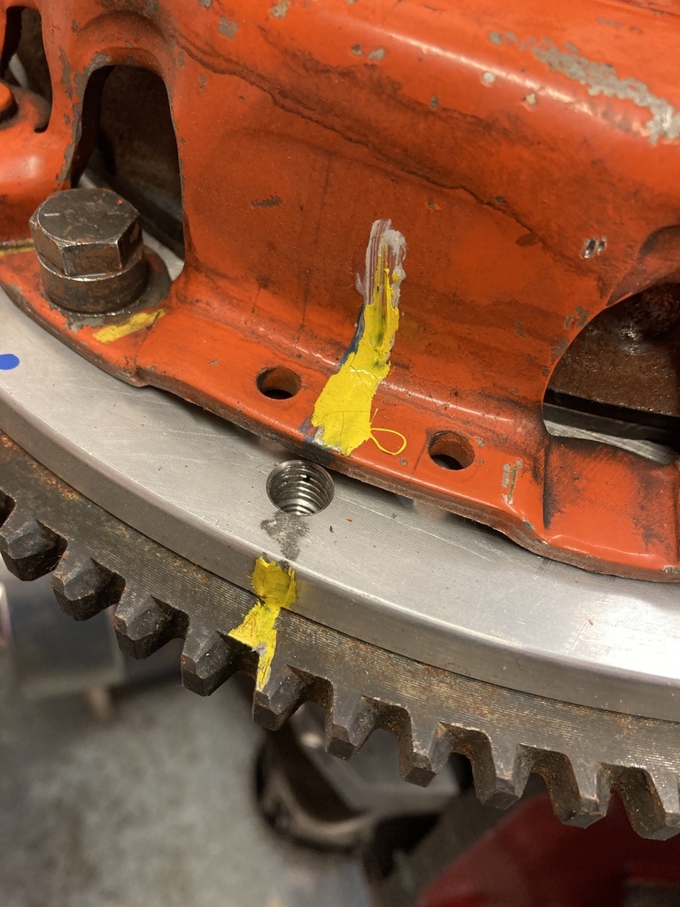 The flywheel to crank was a little more challenging. Two blue marks on the crank and ally flywheel didn’t correspond with the yellow circle around the dowel hole of the stock flywheel. I vaguely remember a dowel being marked yellow at one time but that marking is long gone. The replacement blue marks were put on by me, I would hope in place of the previous yellow ones. I also found some tiny remnants of yellow marker paint around the same dowel. That’s where it’s going then. 50/50 chance of being right. 😆 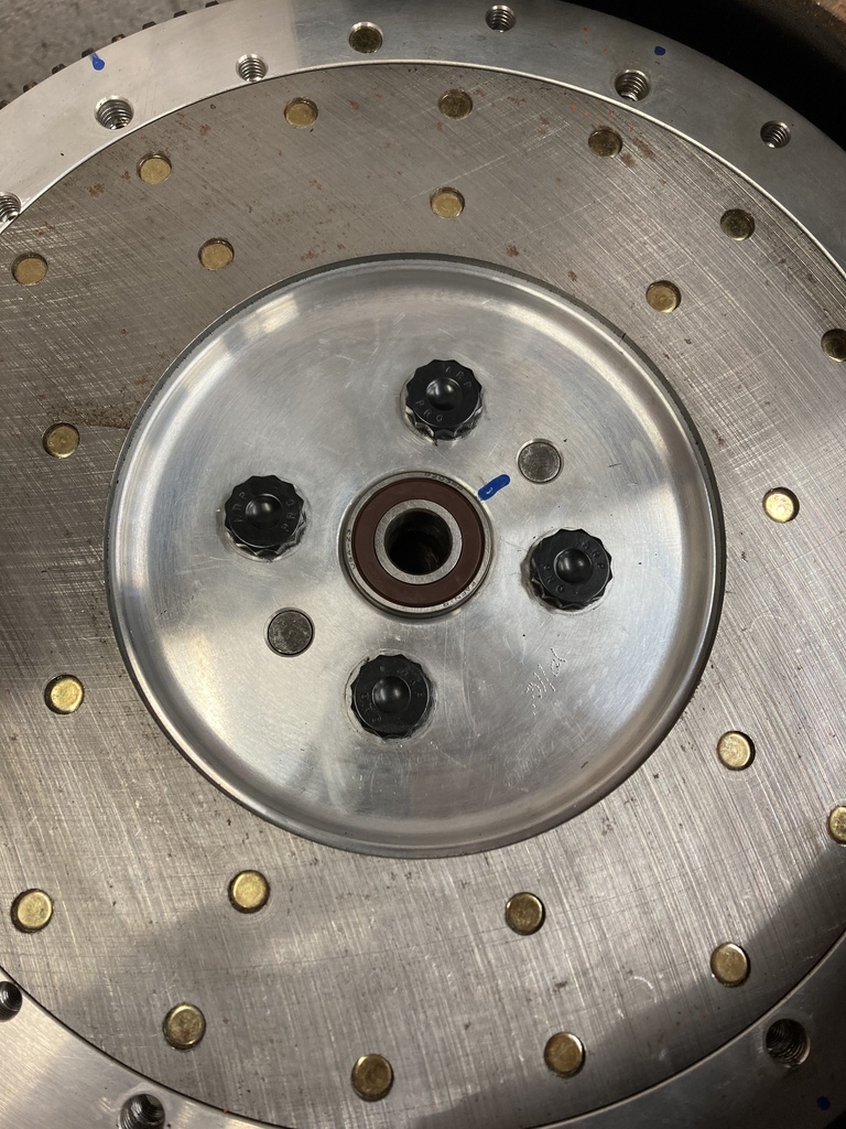 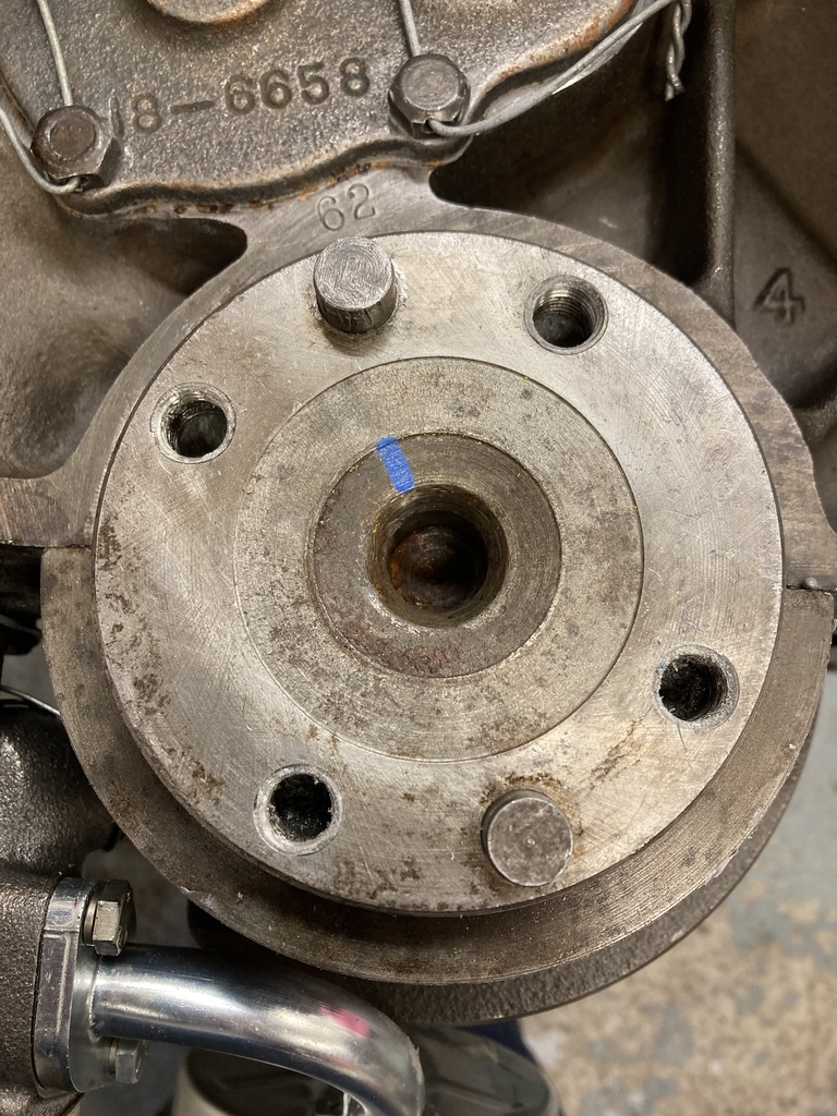 While messing around I remembered that I had cut down the ARP flywheel bolts down. They are Small Block Ford which are correct for the Flathead but the thread is a little on the long side. The ally flywheel is thinner on the centre section so these were now a little short for the stock flywheel. New set ordered. 😔 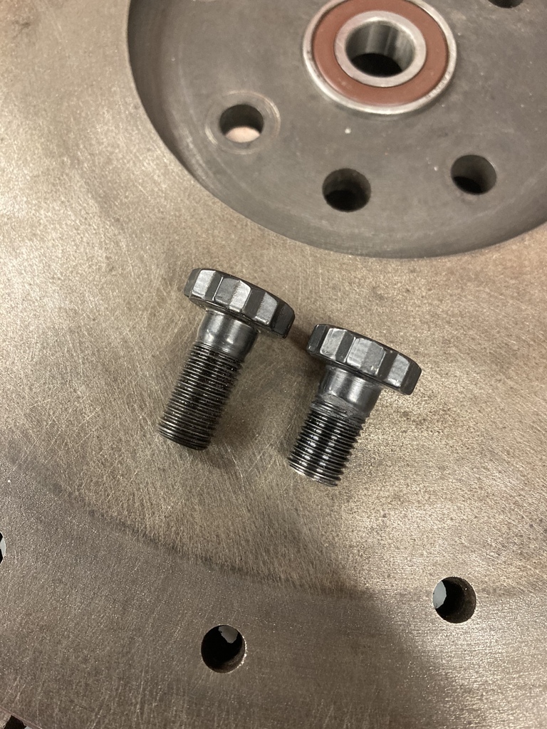 Something to watch for with the ARP bolts is the corner fillet on the back of the head. It’s much bigger than ‘normal’ hardware and needs to be accounted for. 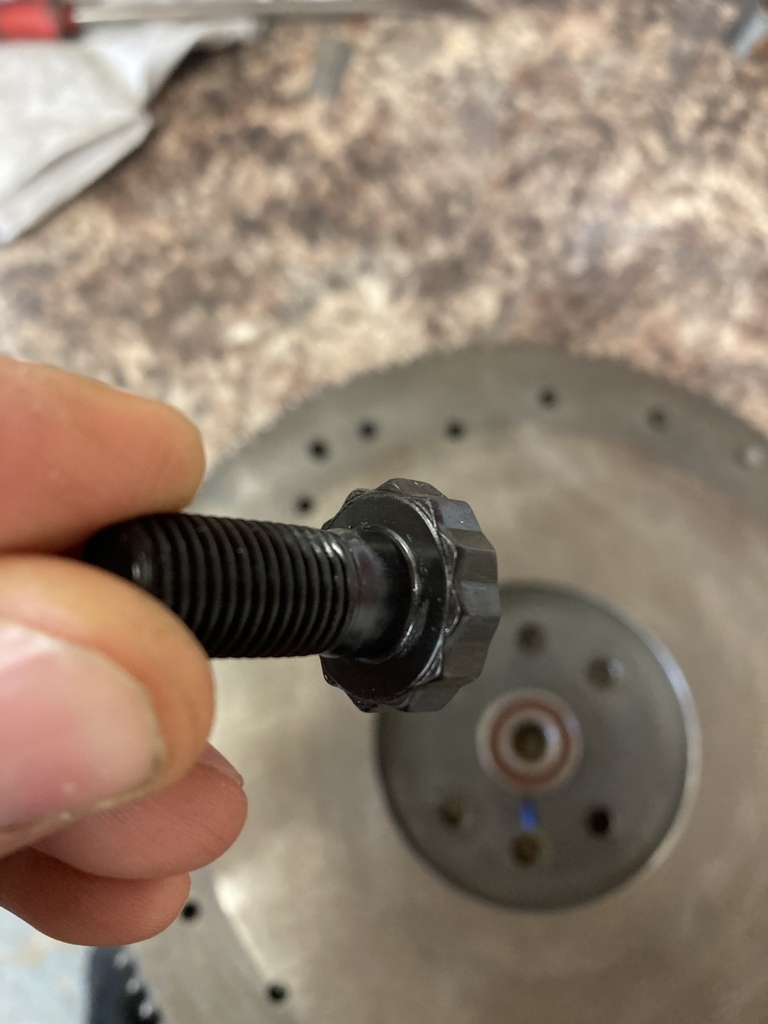 With no clearance around the bolt hole the bolt won’t seat properly as demonstrated here with the feeler gauge. 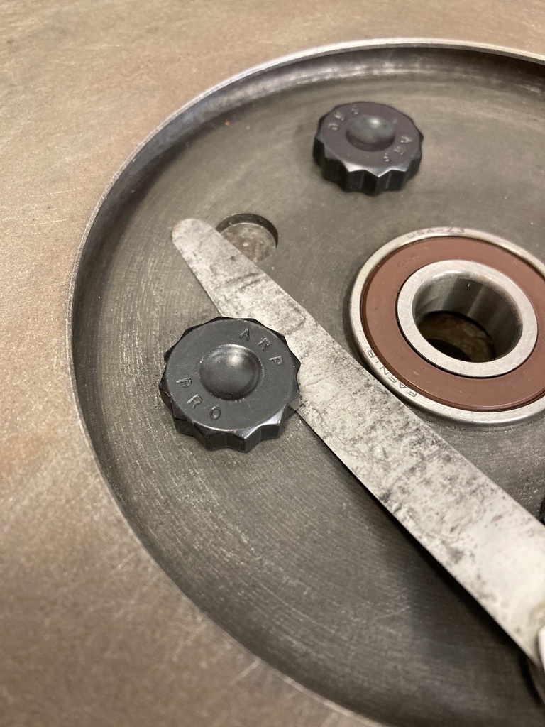 To get a nice, even countersink on each hole I set the flywheel in the drill press. Drifting the chuck out the morse taper so I could replace it with the revolving centre from the lathe. This allowed me to centre up each hole. 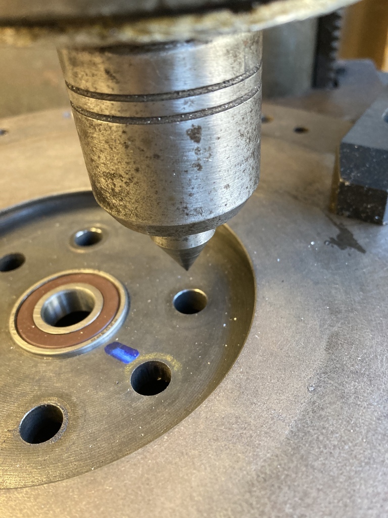 The revolving centre could then be changed back to the chuck with a countersunk and the depth set. Repeat 3 more times. I really need a Mill. All 4 done. 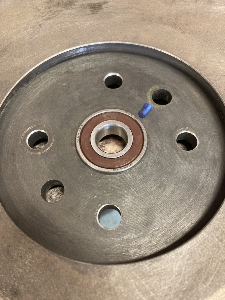 Now you can’t even get a 2 thou feeler under the head. 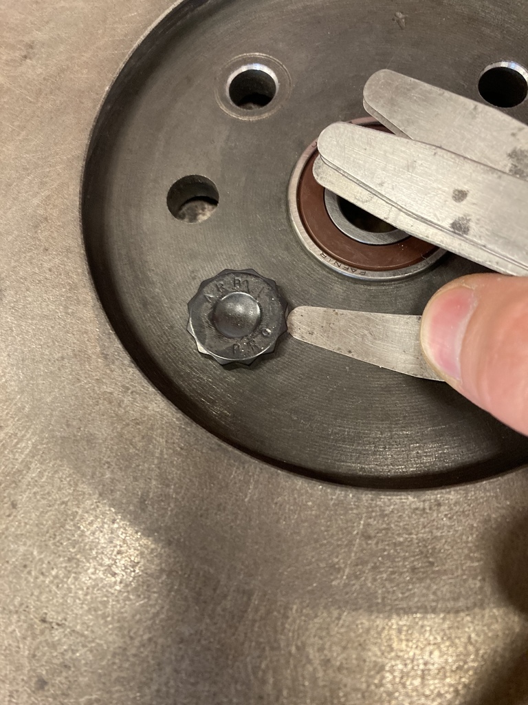 Flywheel bolted on with the new bolts. 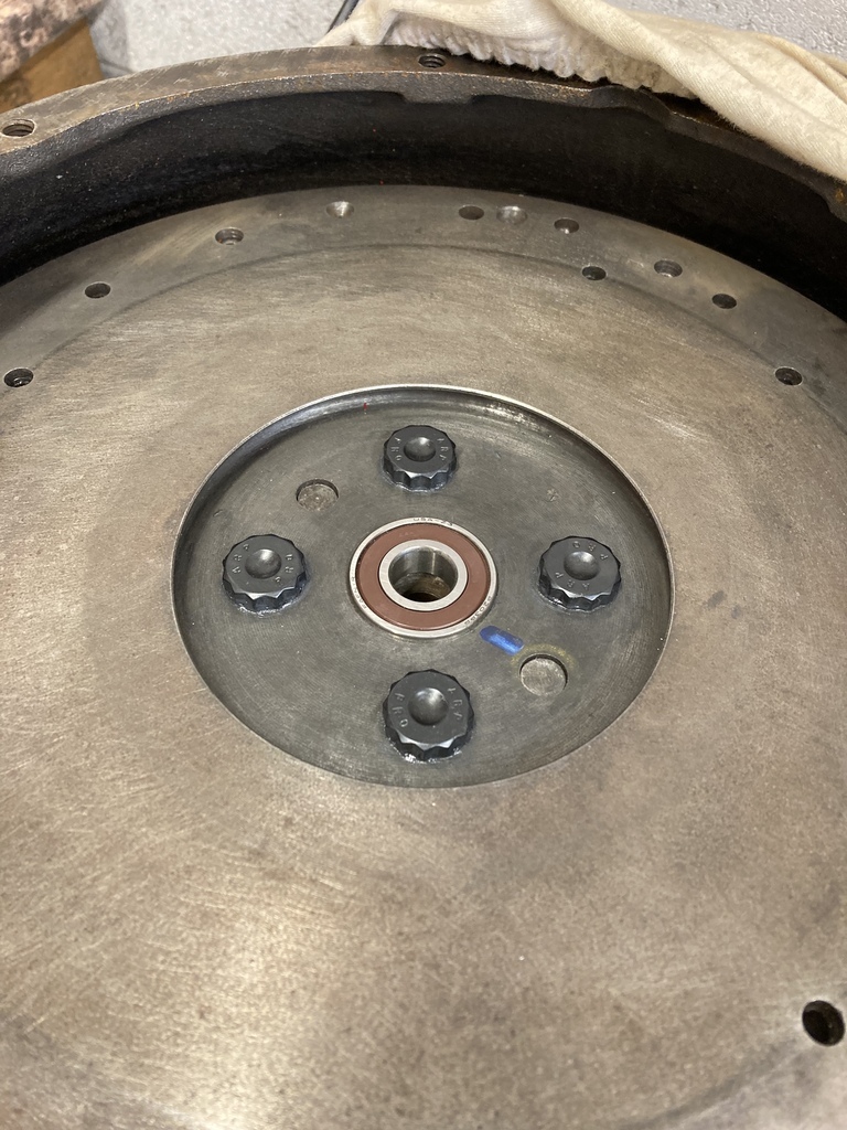 |
| |
|
|
Enbloc
Part of things
 
Posts: 399
|
|
|
|
With the flywheel now swapped and before I bolted the clutch on I turned my attention to checking the concentricity of the bellhousing. Bellhousing on and… not so good. Ignore the “35”. 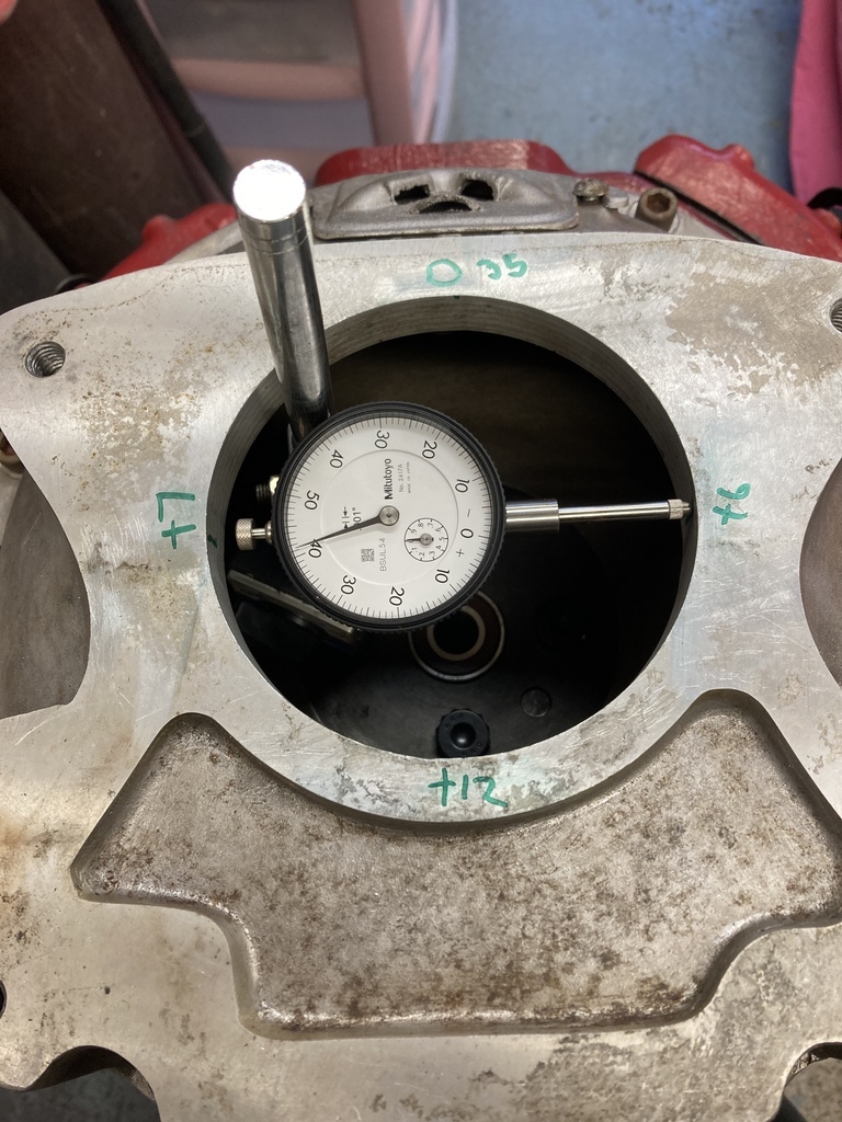 I then continued to check the face for flatness. Not bad. Consistent over 3/4 of the face. Must have a low spot around the top portion. 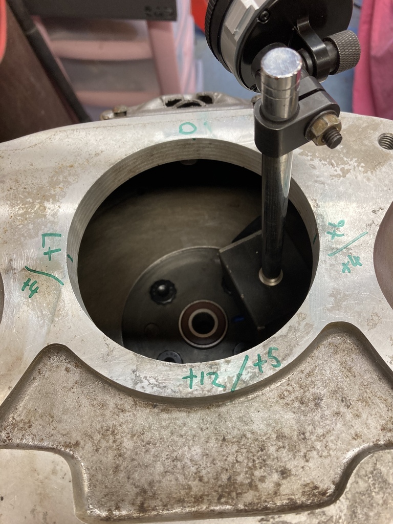 I have an adapter plate between the bell and the gearbox face so I thought I should actually be doing all this with that in place as well. The adapter isn’t doweled but the shouldered bolts do a pretty good job of locating it. Same procedure and a big improvement. No more offset dowels needed. Yay. 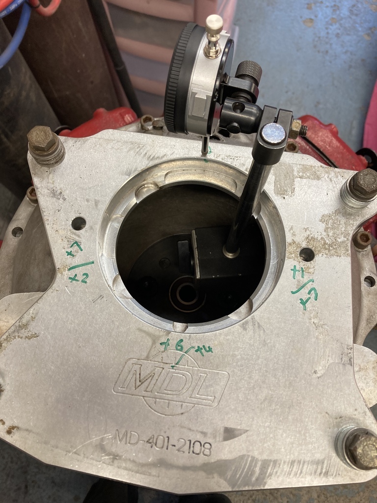 I don’t think this bell is all that in accuracy. I think the dial gauge shows the hole is actually oval. There are also a few mount holes that are off as well. Just general poor quality control. The adapter plate is a Modern Driveline (MDL) part which saves the day here as their stuff is usually spot on. I had done all this with just the bell bolted to the half block face. This is the important mounting face and also contains the locating dowels. 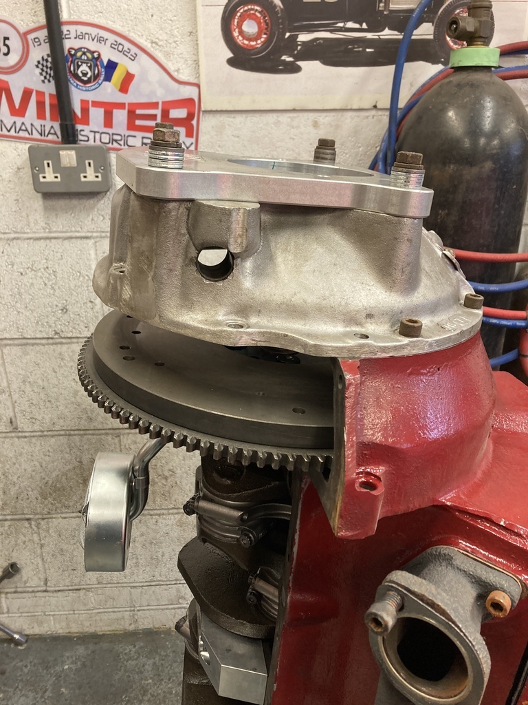 Again, I should really be checking this with everything in place. I bolted the sump up which wasn’t as easy as I thought as without a gasket in place it was mainly guess work. The back of the sump, which forms the lower section of the bell mounting face, is just stamped sheet with captive nuts. Not hugely accurate giving me sufficient gaps like this. 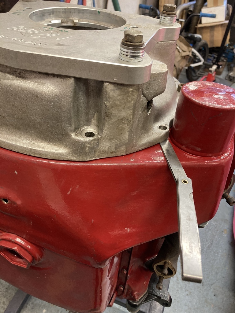 I bolted it all up anyway expecting it to pull the bell out of spec but it didn’t seem to affect it, luckily. 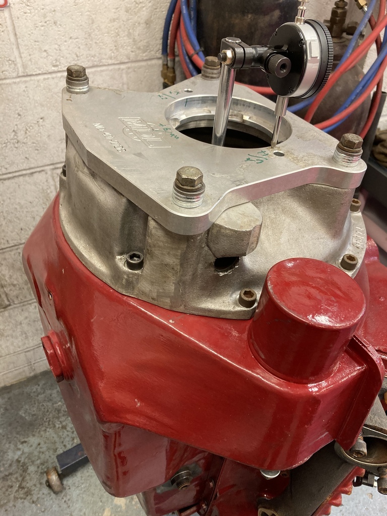 Bolting it all together on the stand reminded me of this annoyance. 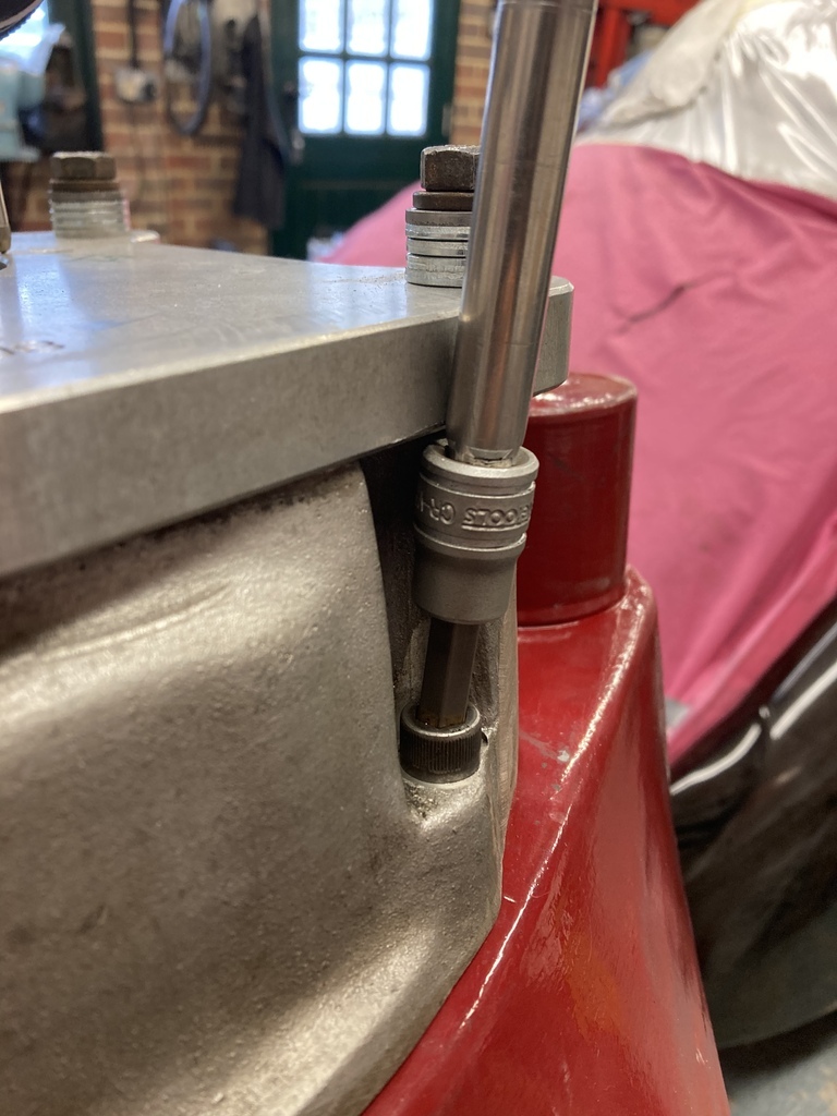 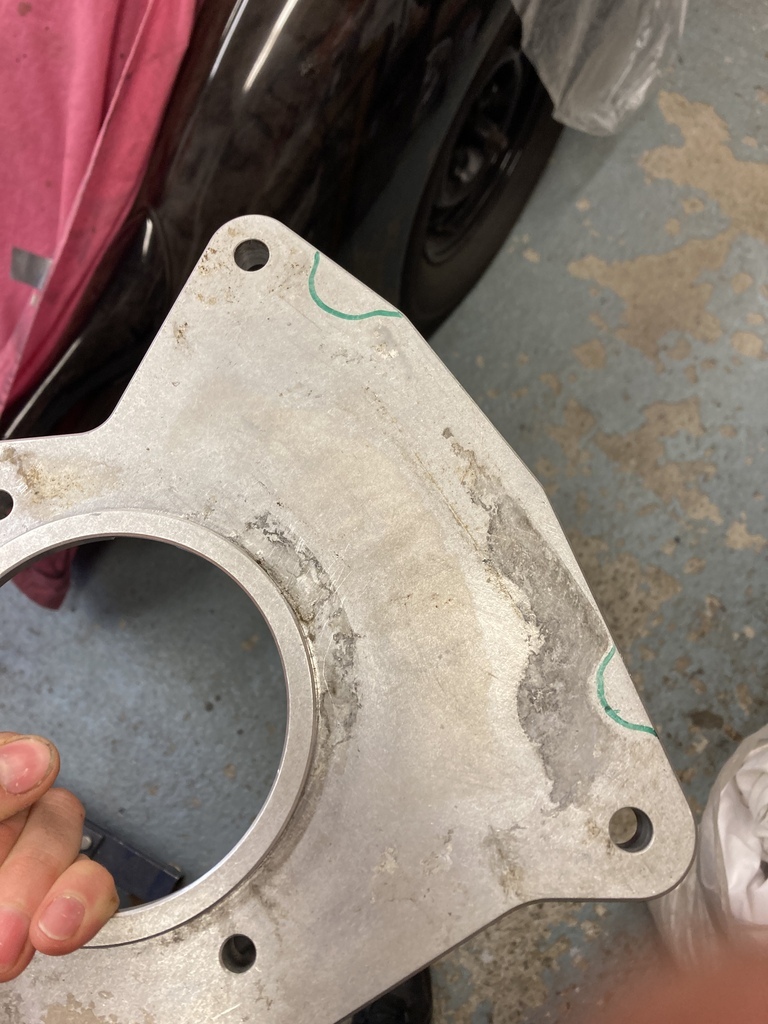 Much better. 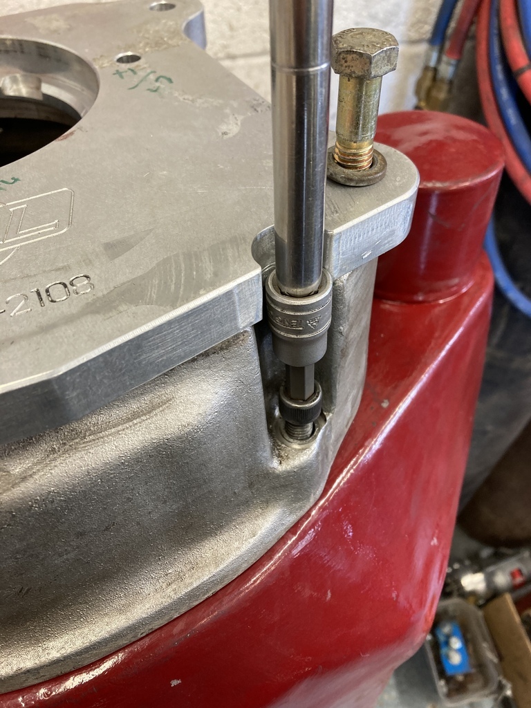 After all that the clutch could finally go on. 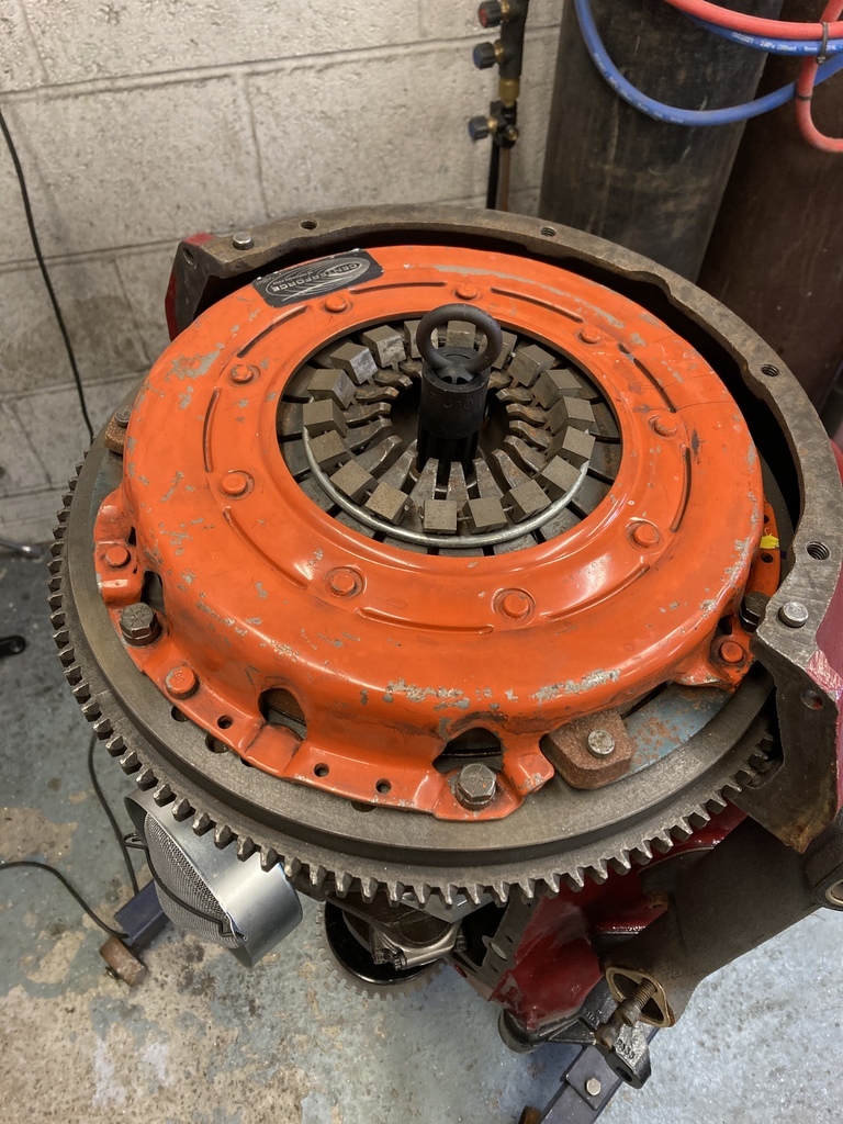 And the sump, hopefully for good this time. 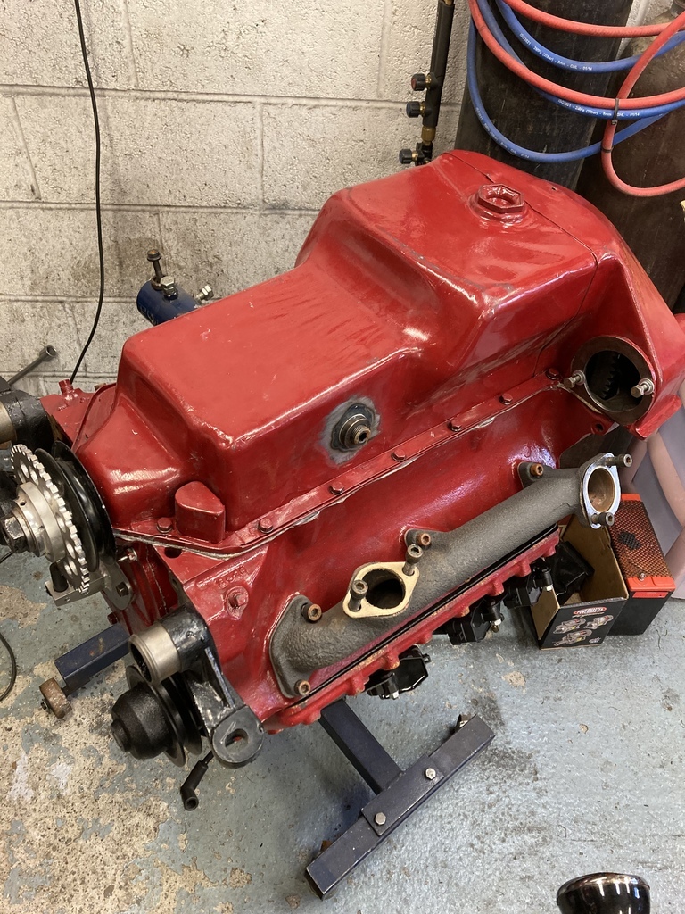 |
| |
Last Edit: Apr 5, 2023 23:21:52 GMT by Enbloc
|
|
jamesd1972
Club Retro Rides Member
Posts: 2,921  Club RR Member Number: 40
|
|
|
|
|
Lots of quality work there for sure.
Ref grease in steering boxes I think you can get away with John Deer corn head grease if you need to. Otherwise known as Land Rover swivel grease as it’s thixotropic and designed to replace oil where the seals have departed.
Looking forward to the finished car as the details are adding up very nicely towards the whole.
James
|
| |
|
|
Enbloc
Part of things
 
Posts: 399
|
|
|
|
Lots of quality work there for sure. Ref grease in steering boxes I think you can get away with John Deer corn head grease if you need to. Otherwise known as Land Rover swivel grease as it’s thixotropic and designed to replace oil where the seals have departed. Looking forward to the finished car as the details are adding up very nicely towards the whole. James Thanks. The original spec lube was something like 600W oil, which is like thick treacle. The modern replacement is known as semi-fluid grease which is what the corn head stuff is. I've been using Penrite for some time now. I guess its all the same stuff just in different packaging. 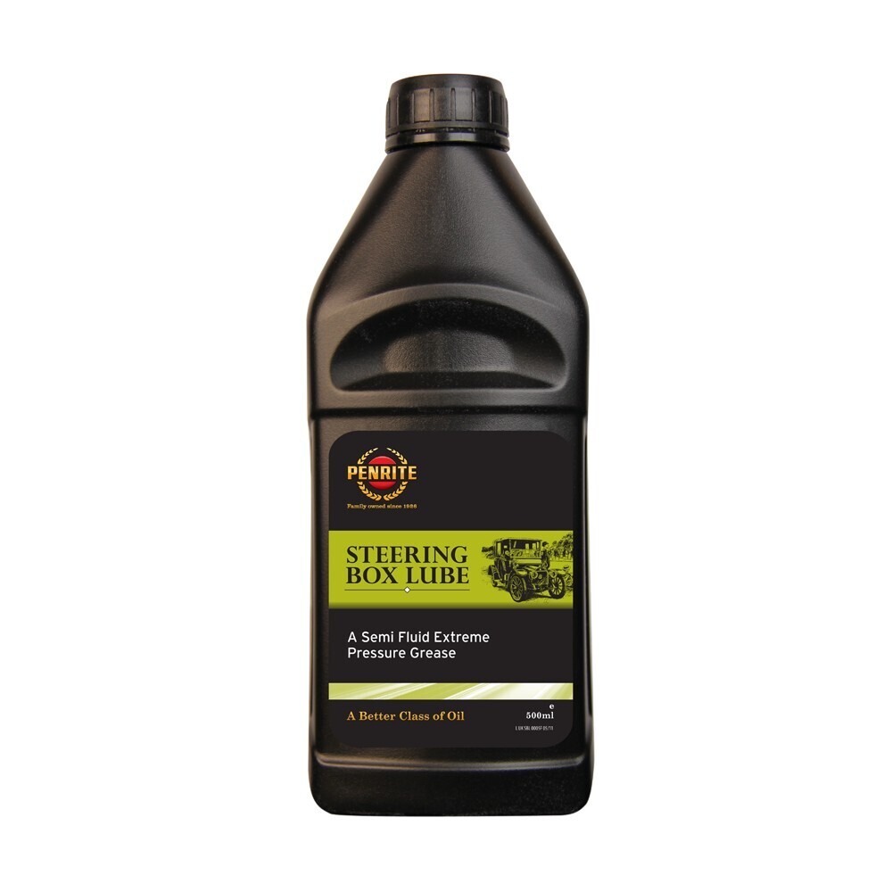 |
| |
|
|
jjeffries
Part of things
 
Posts: 777
Member is Online
|
|
|
|
|
Back in, say, the 1950’s, we’re there British suppliers of go-fast parts for the Ford flathead V8, or did everything come from the US? I’m thinking of Sydney Allard or those with whom he developed his engines? Maybe he just went to Cadillac engines and didn’t actually do much flattie improving? Just wondering. Fantastic work you (and your Dad) have been doing.
John
|
| |
|
|
Enbloc
Part of things
 
Posts: 399
|
|
|
|
Back in, say, the 1950’s, we’re there British suppliers of go-fast parts for the Ford flathead V8, or did everything come from the US? I’m thinking of Sydney Allard or those with whom he developed his engines? Maybe he just went to Cadillac engines and didn’t actually do much flattie improving? Just wondering. Fantastic work you (and your Dad) have been doing. John Thanks. 👍 Regarding British Speed equipment, none really. Allard did produce twin carb inlets and heads. 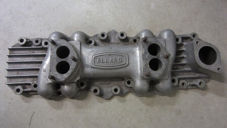 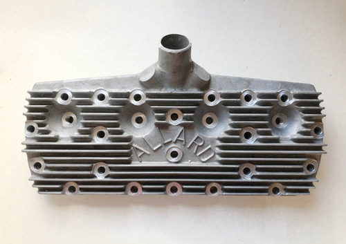 The Allard heads were unusual in that were for the earlier 21 stud blocks. The 21 stud was much more common in the UK being produced into the 50’s with the Ford Pilot so this made sense but on the flip side US production of aftermarket 21 stud heads is almost nonexistent because of the abundance of the later 24 stud engines. Inlets are interchangeable between all the years and variants. It’s worth noting that compared to the usual British period fodder of Austin 7’s, Riley 9’s, Ford 8/10’s and the like that a Flathead V8, even in stock trim, is like bringing a gun to a knife fight! This a great period shot of a very British modified ‘34 Ford at Shelsley Walsh. 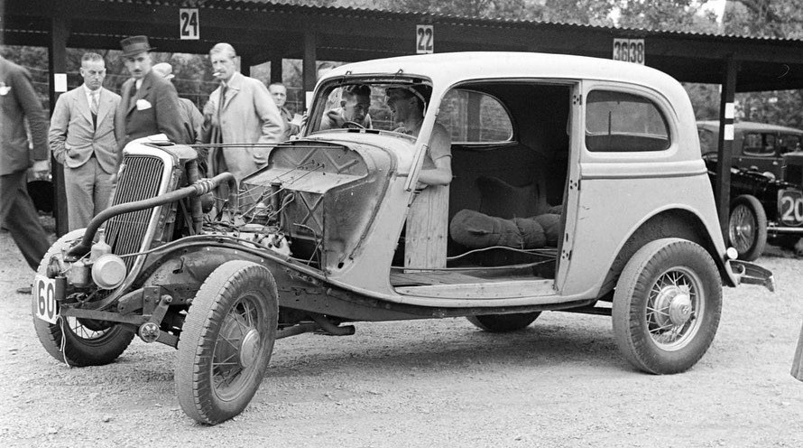 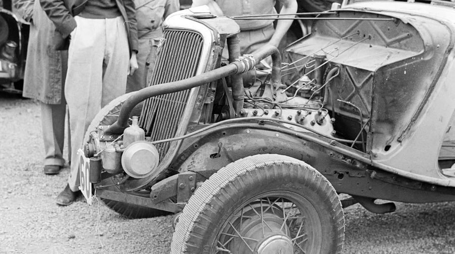 Completely stripped for all the lightness, Hartford friction shocks on the front and that crank mounted shorrock or Arnott blower with large SU carb hacked into the minty grille shell and pipe’d straight into the stock Flatty. This is also a very good read. Ken Coopers memories of racing a Flathead dragster at the birth of British drag racing from the late’s 50’s, early 60’s. There are 5 or 6 parts to the story. link |
| |
Last Edit: Apr 7, 2023 13:44:14 GMT by Enbloc
|
|
|
|


