|
|
|
Feb 21, 2018 13:34:57 GMT
|
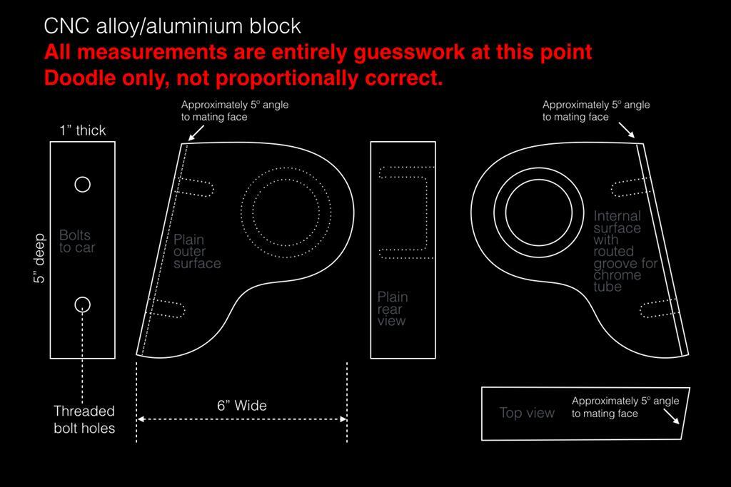
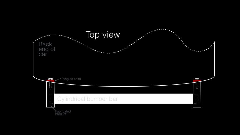
I've never done anything like this before so I'm fishing about int he dark at this point. ===== Background: My car has had bodymods done (which I like) that mean you can't fix a proper original bumper to the rear (the side mounting points are gone as are the indents into which the bumper sits). To save anyone from suggesting I reverse the body mods and fit a proper bumper properly... I don't want to do that thanks. I like the way it looks. So... for the longest time I had no rear bumper and it looked ugly as well as leaving my fibreglass body vulnerable to bumper shunters. Then I chanced upon a rotten old Scim bumper that was rusted through and in a bad way, and it had no mounting brackets with it. That was just what I needed. I cut the ends off and simply bolted it to the car via the two rear fixing holes, securing it in place with some cut down bullet-shaped wheel nuts. The ends looked raw and ugly though so as a temporary bodge-up I shaped some plastic and stuck it over the ends. And that's how it has stayed for about a year. Yesterday somebody managed to pull one off though, so this morning I've had to knock up a slightly more sturdy temporary cosmetic bodge. It's not finished yet, I have to go and add the vinyl covering to smooth it all off once various adhesives have dried...  ===== My plan: Ultimately I want to get around to having a round-section chrome bar running across the back of the car. Dead straight. Just a chrome bar running across the back. I will fix it in the same way... via the two fixing holes in the body that will screw into internal cylinder brackets inside the chrome tube. For the end pieces though I'd like to make them more officially sturdy than just bodging bits of plastic for cosmetic purposes. I'd like to get two identical but opposing brackets CNC'd... a left and a right. These will bolt to the car's bodywork to hold them in place. They will feature either a cup or a routed channel on the inside face to hold the bumper bar (which will be held rigid by the two main fixing bolts) ===== My doodle and my question: So I want to know if it is possible, and how much it might cost, and who I might talk to about making up a pair of these brackets as sketched out below...  Anyone have any suggestions as to who I might talk to? As before, I'm really not looking for the suggestion "why don't you just refit the original brackets and have a proper bumper?" because that's not what I'm after at all with this car. Any suggestions, thoughts, advice greatly appreciated though with regards to having these end brackets made up. = ) |
| |
Last Edit: Feb 21, 2018 13:48:54 GMT by Deleted
|
|
|
|
|
|
|
Feb 21, 2018 21:06:45 GMT
|
|
Apologies... bumping this as it's fallen off the currently active threads list and I'm hopeful somebody out there might be able to advise me/
=)
|
| |
|
|
|
|
|
Feb 21, 2018 21:40:41 GMT
|
|
i guess it will be expensive. For CNC machines you require a precise drawing. All curves have to determined and your rough sketch has to be converted into a precise drawing with precise dimensions. If you cannot make this drawing yourself, an engineer has to do that and that is not cheap. The hourly rate of CNC machines is also rather high so the only way is you find someone who is allowed to make it for you during his lunch time
|
| |
|
|
|
|
|
Feb 21, 2018 21:52:25 GMT
|
|
Not difficult to do. Just one question. Is the recess for the tube also machined in at a 5 degree angle?
|
| |
|
|
|
|
|
Feb 21, 2018 22:04:29 GMT
|
|
No, the recess would be 90degrees to the face.
I would need to get the whole thing properly measured and spec'd up, but once done I would be able to proved accurate flat plan engineering drawings and depending on the file type that CNC uses (I have no idea) i could probably call on one or two old friends from my former career to create a 3D digital model from my flats, if that's what's used.
I guess really it's the question of cost, on the basis that this old clunker of mine definitely doesn't justify £3000.00 bumper brackets.
I don't know much of anything about this stuff, so I guess I was hoping it's all become much cheaper and domesticated lately. An old friend who runs a laser cutting company has been toying with investing in CNC for a while (but hasn't) and knowing him as I do, that has kind of given me the impression CNC is now entering the accessible pro-hobby category level with relatively cheap machines coming on to the market.
|
| |
|
|
awoo
Posted a lot
  
Posts: 1,507
|
|
Feb 21, 2018 22:33:48 GMT
|
|
you could do that with a lump of ali and some basic tools.
cut the shape roughly, finish it with a file/linisher.
bevel the edges to that angle you want with a file/linisher.
drill the holes.
use a hole saw for the bar recess.
that's what I would do anyway, since you only need two.
with a linisher it would be pretty easy/piece of curse word
|
| |
|
|
awoo
Posted a lot
  
Posts: 1,507
|
|
Feb 21, 2018 22:36:27 GMT
|
|
just looking at it, if you're going to have a 5 degree angle on the mating face you would need an equal angle on the bit holding the tube.
|
| |
|
|
|
|
|
Feb 21, 2018 22:59:59 GMT
|
|
Where abouts in the south east are you quatermass? Id probably pop into f1moto/driftmoto at brands hatch, they machine bits and pieces or would prob no someone who does.
|
| |
Last Edit: Feb 21, 2018 23:00:19 GMT by jaykay
|
|
|
|
|
Feb 21, 2018 23:53:07 GMT
|
|
I did wonder whether it might be possible to do it by hand.
The 5 degree angles (probably more like 3 actually) are to counter the bow in the back of the car and the holes for the bar would definitely be as they are in the diagram.
The two pieces would stick straight back, parallel to each other. The angled back surface enables them to do so on a bowed surface... So the holes would be 90degrees to the material's face.
Without the 3 degrees (my crappy phone doesn't have a degree sign on the keyboard) the two brackets would splay out and the holes for the bar would have to be drilled at 3 degrees to correct it.
|
| |
|
|
|
|
|
|
|
|
Ok. So then I take it if the hole is parallel to the face,then the mounting holes need to be drilled in at the same angle as that bit that is used for mounting it ,i.e. At 3 or 5 degrees?
No need for a 3d model ,waste of time and money for such a simple 2d part. Wouldn't be difficult to program pretty much from the drawing you have,given a few more dimensions. Problem with most people's , " engineering " drawings normally,Is who ever draws it makes it look all good ,but not seen by eye,but seen by the Cnc machine are the multiple lines on top of each other and the little ,call them minuscule,gaps between say the end of one line and the beginning of an arc.. These come about when two entities are trimmed ,and these tiny gaps or overlaps makes it impossible to chain to cut the contour.This is all related to the settings/ tolerances used in the cad program . A gap of ,0,001mm is enough for my program to think it's reached the end of the chain. Similarly,if you have a two lines on top of each other,when the program gets there,it sees it as a branch point and even though the lines have supposedly the same z value,it doesn't know what line to follow. Let's not get started on the subject of draftsmen who know the difference between model space and paper space,always fun looking for a drawing that has been drawn 17km away from the origin.....True story...😂😂😂
I seem to spend more time sorting out other people's drawings than actually machining. Then you get ,'" But I supplied a CAD drawing". Yes you did,drawn by a Cad who has never machined anything in his life 😂😂😂
Your drawings as they are ,with dimensions will be way quicker for me to program,as I can draw that part in minutes that will chain first time out.
Wouldn't be overly expensive to do, bearing in mind custom Cnc work isn't cheap and you pay for the time your material is on the Cnc mill. With me doing the CAD drawing and supplying the material I would imagine you are looking sub £200 for the two....I would have to confirm material costs beforehand though.Parts would be supplied as machined from Aluminium plate.This would need to be polished up after machining as normally it's supplied in a dull grey finish with batch numbers etc printed on the surface. Polishing and anodising would be for you to arrange.😊
|
| |
Last Edit: Feb 22, 2018 5:25:36 GMT by Deleted
|
|
|
|
|
|
|
|
|
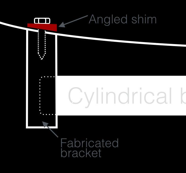
Hey Johnnybravo, Thanks for your thoughts on this. Much appreciated. In terms of the 5º (or 3º) angle in the mating face... my thoughts are actually that the whole thing could be made with everything square to the material face, and then those mating faces could shaved to the correct angle at the fitting stage (ie by me, with an appropriate tool and a vice). Doing it absolutely absolutely properly would imply that the two drill holes on the mating face ought to drilled at 90º to the mating face angle too... but they will be completely hidden and aren't load bearing at all, so I would find or make an appropriately angled shim washer to go on the reverse, like this...   So, it sounds like you are saying you could possibly do this. I would need to supply accurate and clearly marked flat engineering blueprint style technical drawings and it could be done from that up to (pre) final finishing. I'd be really interested in doing that. I would imagine it will be a while before I am ready to start working out accurate drawings as I will need to mock it all up at the correct position.... I want the bumper bar to go slightly wider than where the current bodged bumper resides, which will change the geometry of the pieces away from what I could measure right now with my plastic end-piece mock-ups. I guess the first thing for me to do will be to find the right diameter bumper bar to use and cut it to the desired length. Once I've got that I can work out how much clearance will be needed at either end to miss the centre of the car's rear bowed line. Then I can know for sure what the overall material size needs to be and set about measuring up the shape and fitting points. So for now, thank you (et al) for your help. I'll go away and start looking into this and I'll come back for thoughts when I have some accurate diagrams done properly at the correct proportion/scale. If it turns out you aren't able to help me at that point that's totally okay... no pressure!... because you've been massively helpful already and I at least know it's feasible now. Cheers! Woo! |
| |
Last Edit: Feb 22, 2018 8:35:43 GMT by Deleted
|
|
|
|
|
|
|
Feb 23, 2018 22:36:27 GMT
|
|
Just one point, you don't need a circular channel to fit the tube into, it has no advantage and would need to be machined using a very small cutter and take time. Just a plain counterbore would do the same job and nobody can see the boss that you effectively do or don't have inside.
If its just a round hole with flat bottom it could be machined out by the same tool and in the same setup at the profile and cost less.
Not difficult for someone to make, costly at precision machine company rates but what you want is someone who works at such a place and wants to do it during lunch breaks or after work for beer money
Last consideration, ordinary bare aluminium will take regular care to prevent corroding if you use the car a lot and especially in winter.
Ideally it could do with anodising, maybe in a batch of stuff from the same place that makes it.
If you don't want to paint them or polish a lot, or anodise, then you could make them from stainless instead, maybe thinner for weight reduction.
You could then use stainless pipe for the bar and polish the lot.
|
| |
|
|
|
|
|
|
|
|
Hi Chris,
Yeah, I figured it might be easier without the centre lug in the main holes, but for now I left it in to see what kind of response there would be to that. I had it in mind that the central lug could be useful to discretely pin the brackets to the central bar (itself fixed firmly to the car) and make the whole thing a little more rigid. I could do that by pinning through the outer bracket, the bar, and into the the core lug thing, but all done from an invisible point.
Without that the brackets would possible only be held in place through the fibreglass (I haven't reminded myself how things look behind the fibreglass at this point so there may a way to make supporting brackets behind there rather than merely bolting in to the fibreglass).
But you're right, and I was aware that was probably a detail I would ultimately lose.
As for the material... it would be my intention to paint them/coat them to match the car, and only the bar itself would be chrome or stainless. I think if the brackets were also chrome or stainless it would all look a bit odd.
|
| |
Last Edit: Feb 24, 2018 0:21:43 GMT by Deleted
|
|
scimjim
Club Retro Rides Member
Posts: 1,503
Club RR Member Number: 8
|
Noob with CNC question....scimjim
@scimjim
Club Retro Rides Member 8
|
Feb 24, 2018 21:24:57 GMT
|
My sprint car had the recesses filled but I had to have a bumper fitted in standard class - I just redrilled the two mounting holes and was careful not to scratch the side when fitting it.  |
| |
|
|
|
|
|
Feb 24, 2018 23:46:08 GMT
|
|
Nice Jim!
I didn't know you had another one. I thought you just had 8ball and one or two SS1s.
The thing is, I don't want to refit an original bumper. I really like the smoothed out sides look with no bumper wrapped round.
I also really like the way a short bumper looks across the back. It's purely personal I know, and mine is quite a shabby set-up, but I actually prefer the short bumper I have.
When I do the rear bumper with a straight bar I'm planning on having two short straight bars on the front too.
You going to be at RR Goodwood Jim?
|
| |
Last Edit: Feb 24, 2018 23:46:59 GMT by Deleted
|
|
scimjim
Club Retro Rides Member
Posts: 1,503
Club RR Member Number: 8
|
Noob with CNC question....scimjim
@scimjim
Club Retro Rides Member 8
|
Mar 13, 2018 22:52:59 GMT
|
I prefer the smooth rear 😬 but had to fit a bumper for the roadgoing regs at the time. I rebuilt that car from a wreck in 2000, drove it to Germany, blew the gearbox up on an autobahn on the way and it spent 3 years in my hangar. Towed it home and changed the gearbox then sprinted it in 2005. Sold it to a guy who worked in London and parked it on the street. He sold the number plate, then the car which ended up as an unfinished kit car (Sammio G46). Now I only have 8 Ball, diesel, snotty, G97, Sarah’s coupe, number one, Megan, Grawpy, flying broomstick and half a dozen other disassembled SS1s to worry about  |
| |
|
|
awoo
Posted a lot
  
Posts: 1,507
|
|
Mar 13, 2018 23:02:32 GMT
|
|
were you driving this down Brighton seafront the other day, I saw one of these with a pancake on the roof... thats how I think it might be the same car...
|
| |
|
|
|
|
|
|
|
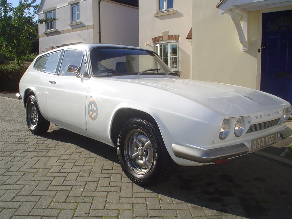
Well I don't know. I don't have an actual pancake on the roof, but I have recently ripped out a sunroof and patched over the hole with a sheet of tin until I decide how to fill the hole, so maybe you saw me before I coloured the tin and it was held down with big silver bolts maybe. Probably was me, but I cant remember why I might have been driving down Brighton sea front. I look like this...  ^ only available picture on my phone. |
| |
Last Edit: Mar 14, 2018 1:03:07 GMT by Deleted
|
|
awoo
Posted a lot
  
Posts: 1,507
|
|
Mar 14, 2018 19:41:56 GMT
|
|
just saw a dark schim the other day in traffic near the west pier, and it had a noticeable patch over the sunroof area. (probably should have put this in your sunroof thread to be more in context!)
|
| |
|
|
|
|


