|
|
|
Apr 29, 2016 23:03:34 GMT
|
|
Very nice work. Impressed.
The Lancia Stratos has always been my favourite rally car.
Did they have to rename the kit car a Strato's in order to avoid copyright issues?
|
| |
Last Edit: Apr 29, 2016 23:04:59 GMT by nalesutol
|
|
|
|
teaboy
Posted a lot
   Make tea, not war.
Posts: 2,125
|
|
|
|
Did they have to rename the kit car a Strato's in order to avoid copyright issues? The real ones had the apostrophe on the door script.  |
| |
|
|
|
|
|
Apr 30, 2016 14:51:09 GMT
|
|
Well, you learn something new every day, if you are prepared to listen and learn :-)
A little research confirms that the original name is STRATO'S. Weird but true.
|
| |
|
|
Darkspeed
Club Retro Rides Member
Posts: 4,882
Club RR Member Number: 39
|
|
Apr 30, 2016 15:07:51 GMT
|
This is coming on so well. I've been clearing out some old kit car magazines and I had a good read about the Gerry Hawkridge / HF series Stratos's this afternoon. They really are such amazing looking cars. I would definitely like to see/hear more about the G32 though, long been a favourite of mine. I will do a separate thread on the Ginetta's at some point as there would be too much to cover within this thread. The G32 is a great little car very underrated as they as just so rare. Did they have to rename the kit car a Strato's in order to avoid copyright issues? The real ones had the apostrophe on the door script.  As teaboy correctly points out - Strato's is the correct Lancia/Bertone spelling  - Sometimes I forget the ' - I have not heard of any copyright issues with the Strato's bearing in mind that replicas have been in production since 1985 It's a mad thing the Strato's - everytime I uncover it to work on it it makes me smile it's just so utterly bonkers and original. |
| |
|
|
|
|
|
Apr 30, 2016 16:19:11 GMT
|
|
I only mentioned copyright issues as I hadn't realised that Strato's was the correct spelling and thought that the replicas added the apostrophe as a way of avoiding copyright problems.
I love learning, and unlearning, things.
|
| |
|
|
Darkspeed
Club Retro Rides Member
Posts: 4,882
Club RR Member Number: 39
|
|
Apr 30, 2016 16:55:45 GMT
|
It's certainly an unusual use of an apostrophe. nalesutol - although not taking things to the sort of levels/extremes you do with regard to "simplicating and adding lightness" I do follow the mantra that anything that gets taken off gets lightened before it goes back on again so with that in mind and the day being a bit damp at times I decided to remove a bit more ugly. 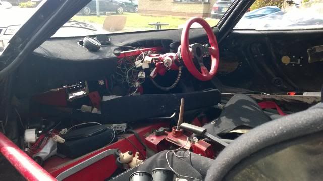 You can make out in this photo the gearlever - not a pretty sight and one which does not sit well with me at all so I decided to remove all of the standard bits of surplus Rover surrounding the ball joint. So here we have the offending item - please note the "bush" in the rear bushing. 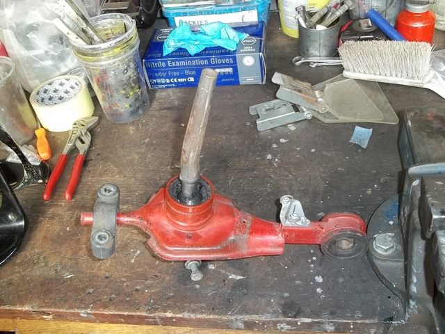 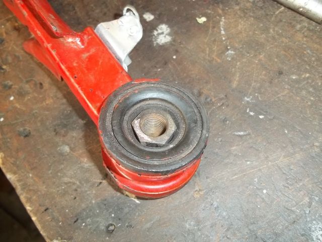 Yep that's a wheel nut with the centre drilled out! 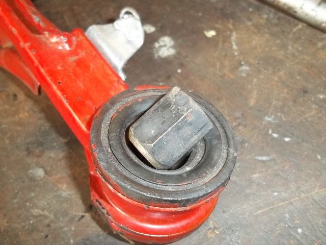 When I have finished this car the cockpit will be, to most, a pretty uncomfortable place to be - it will be very comfortable to sit in for the purpose of driving the car, as I cannot abide the seating position, pedals, steering to be compromised because for me cars like this are for driving - but it will be noisy, hot and claustrophobic so I have no need to have the gearstick mounted between two huge rubber isolators. I want the feel to be positive not remote. Chop chop 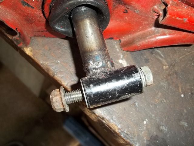 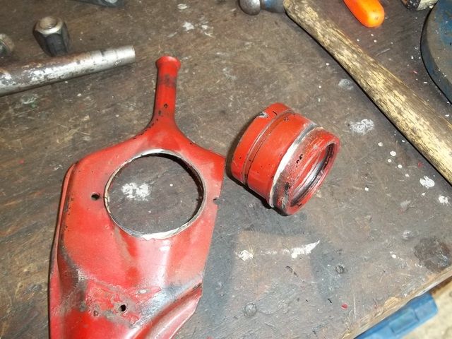 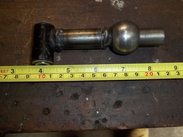 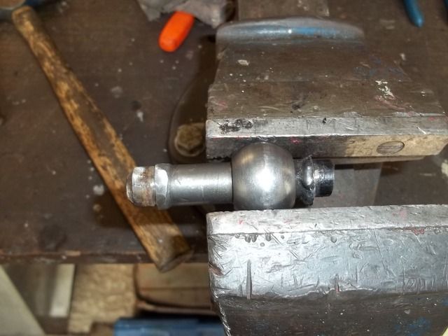 The bits to be kept. 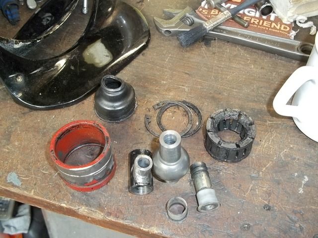 The ball joint and the joint to the lower bush were not hollow - that's my bit of making things a little lighter - The lower bush is also rather OTT as the sleeve is between thin nylon bushes and the sleeve is insulated by having 4 o-ring grooves and o-rings ! The ball is also insulated from the housing by the assembly being held in two large o-rings. They will be more than enough of a nod to comfort for me. Put them away in a box for the assembly work. |
| |
Last Edit: Apr 30, 2016 17:19:59 GMT by Darkspeed
|
|
Darkspeed
Club Retro Rides Member
Posts: 4,882
Club RR Member Number: 39
|
|
|
|
Whilst at the kit car show yesterday I picked up another part from Lister Bell. This is the Steering column support bracket that they produce - I just had to have one even though it will be completely unseen up under the dash I will know it's there  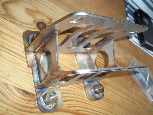 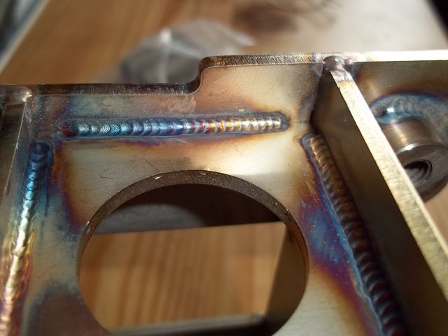 Next on my list of little sundries to save for. 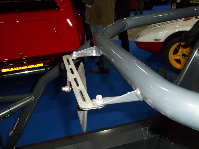 |
| |
|
|
duncanmartin
Club Retro Rides Member
Out of retro ownership
Posts: 1,320
Club RR Member Number: 70
|
|
|
|
I love it when people post up pictures of the beautifully engineered and fabricated bits that are going to be buried in the bowels of their car and never ever seen. Quality engineering...  Cheers Duncan |
| |
|
|
Darkspeed
Club Retro Rides Member
Posts: 4,882
Club RR Member Number: 39
|
|
May 18, 2016 19:38:59 GMT
|
Inspired by one Mr @johnnybravo I thought I would have a thread diversion into a tool built for a task with the project(s) A while back I decided to build myself a flowbench, I had enjoyed modifying cylinder heads with a bit of simple porting following the guides on Pinto tuning by Mr Vizard and tweaking Rover V8 heads from information given to me by people who had vast experience in making good power from them, but being an engineer I was unhappy about not being able to measure the improvements being made even though I had no reason to doubt the information written or the advice being given. There are generally two choices when it comes to measurement of modifications to an engine that have been carried out to improve power. Choice one is building the engine up complete and putting it on an engine or a chassis dyno and measuring the power produced - preferable against an original datum so that direct comparisons can be made. The other measurement is with a flowbench. And engine being an air pump its ability to pump air has a direct relation to its ability to make power and therefore the cylinder heads ability to flow air is also directly related to that ability to produce power. Buying a professional flowbench for the odd bit of home porting is prohibitively expensive so the amateur head fettler has a couple of options - do without or try and build one. Lucky for me I started to get interested in flowbenches just when a chap in the USA was offering plans for sale on a bench design he had designed. www.flowbenchtech.com/Armed with a set of plans delivered in the good old method of paper in the post from the USofA I got stuck in with the build. Somewhere on an old PC or laptop there is a file with all the flat bits of MDF on it so you are sped along to the ones I can find with part assembly already complete. 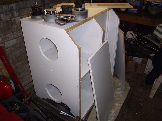 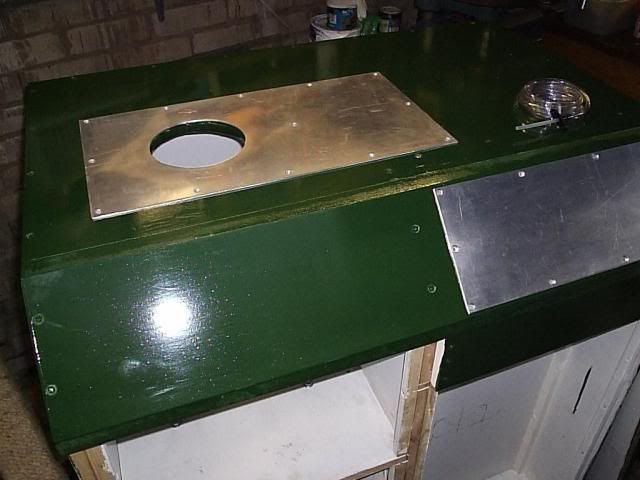 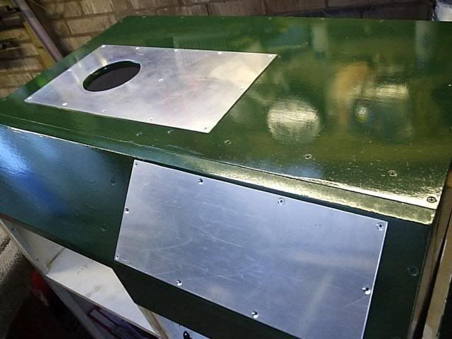 And now I have to go and hunt out those files. |
| |
|
|
|
|
|
May 18, 2016 19:48:58 GMT
|
|
spanner in the works moment, its not all about flow, but what the air does, plus pulse tuning, cam timing, exhaust primary vs secondary lengths vs inlet pulses....
i know a very successful engine builder and mapper who doesn't use flow benches at all.
|
| |
|
|
|
|
|
May 18, 2016 19:59:13 GMT
|
|
This is a really cool thread. Honoured to be tagged in it. Think it's great that you show something that you make to go forward with your project. Something that is relevant to your project and the direction you are going. A lot of people may not get it...until they are either their themselves ,the cheque book is broken, or they just can't get what they want done. So, good on you. Yes, you will get the naysayers, but at the end of the day, your build,your rules,and let's see what's relevant to you...
So yes, some people don't need flow benches. Some are really gifted. But millions of people have "ported" heads, the majority of which most likely are now worse,airflow wise than before. So, kudos to you to take the time to build a pukka bit of kit to actually quantify wether or not your judicious use of a die grinder has yielded improvements or not. Subscribed....
|
| |
|
|
Darkspeed
Club Retro Rides Member
Posts: 4,882
Club RR Member Number: 39
|
|
May 18, 2016 20:19:20 GMT
|
spanner in the works moment, its not all about flow, but what the air does, plus pulse tuning, cam timing, exhaust primary vs secondary lengths vs inlet pulses.... i know a very successful engine builder and mapper who doesn't use flow benches at all. Plenty don't use benches - but everyone who takes the job seriously does - and throw as many spanners as you like - power is all about flow - more flow is more power - less flow is less power. Feel free to start a tread elsewhere to argue that one but this is my thread diversion about a bench build. Please don't be offended if I don't respond further on the subject. |
| |
|
|
|
|
|
May 18, 2016 21:00:13 GMT
|
|
to aid my understanding, the hole in the alloy plate is the replacement for the top of the block and you will suck air out of the chamber below using what looks like a vacuum cleaner motor? how are you planning to measure flow rate?
|
| |
|
|
Darkspeed
Club Retro Rides Member
Posts: 4,882
Club RR Member Number: 39
|
|
May 18, 2016 21:01:46 GMT
|
Whilst I fail to find the bench pictures that I want I may as well run through the specifications on this thing. The PTS bench is an orifice bench and a ratiometric device which basically means that it measures flow across a calibrated sharp edge orifice and that as the air through the head is at the same temperature as the air through the orifice it is self compensating so all you need to do is allow for the atomospheric temperature in your calculations. Other types of bench need a bit more effort in the calculations. I am being brief as everything you would need to know is out there to find. I liked this bench design as it also has the facility to flow the exhaust ports in the direction of flow of the gas in the engine by reversing the bench flow. Typically you would just take the exhaust flow in the same manner as the inlet port but with this you can check the measurements you have and see if any anomalies crop up. I built the bench to the full specifications of 8 vacuum motors - each is about 1300 watts so flat out its drawing a fair bit of power - single phase 10.4kW or 13HP or about 42 Amps (again a simplistic calc) so a bit of a draw on the garage socket  At 8 motors the bench can pull over 40" inches of water vacuum at a flow rate of 450CFM - you will have to take my word for it that its moving quite a lot of air and that's quite a pressure drop. The Rover heads I was playing with have a maximum flow potential of at the very best 200CFM at the standard 28" pressure differential so with that I blocked off 4 motors before I had to find a way of putting the smoke back in the house ring main. Getting it back into Heated rear window circuits in old Fords is hard enough. Wonky picture showing the orifice plate in the settling chamber that sits under the port any fixture sit on. The studs hold a baffle and the chamber is there to slow the air once its been rattled past a valve and give it time to sort itself out so it can pass nice and orderly through the orifice - chambers and baffles are mirrored because of the ability to reverse the flow. 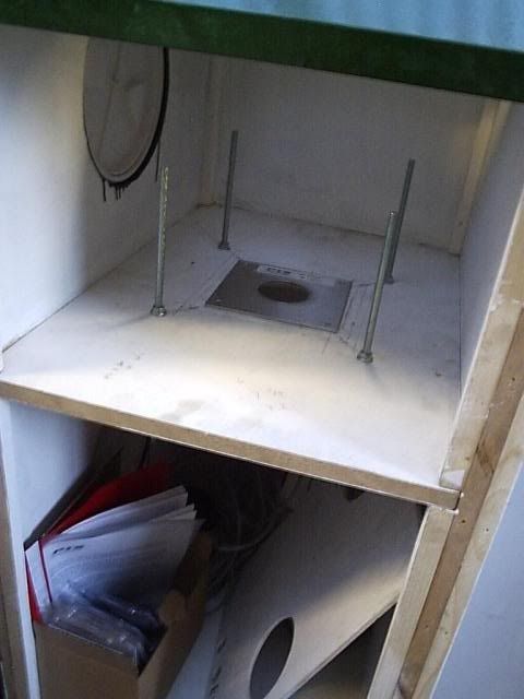 There are access ports to the side are so that the plates can be changed for different sized orifice diameters and that it can also be turned over if you wished to reverse flow throw the same side of orifice - more on that later. |
| |
Last Edit: May 19, 2016 6:51:44 GMT by Darkspeed
|
|
Darkspeed
Club Retro Rides Member
Posts: 4,882
Club RR Member Number: 39
|
|
May 18, 2016 21:13:14 GMT
|
to aid my understanding, the hole in the alloy plate is the replacement for the top of the block and you will suck air out of the chamber below using what looks like a vacuum cleaner motor? how are you planning to measure flow rate? All will be revealed as I progress - the plate on the top is just a plate to provide a nice flat surface to mount and seal any fixture to - The fixtures that you build are what mimic the cylinder you are emulating. Measurement on this bench is fully digital with pressure sensors measuring across the calibrated orifice. Looks like this in operation. To be added when PB gets its act together 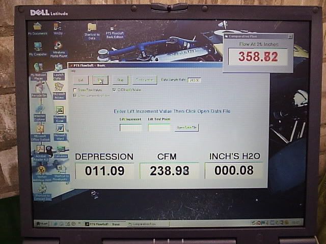 |
| |
Last Edit: May 18, 2016 21:32:41 GMT by Darkspeed
|
|
Darkspeed
Club Retro Rides Member
Posts: 4,882
Club RR Member Number: 39
|
|
May 18, 2016 21:57:46 GMT
|
This is the main motor board - I manged to find 4 quite powerful 2 stage motors which are the ones that I use in the main now that the other fours have been blanked off. They can flow a fair bit on their own and will easily take a well ported Rover V8 to the limit of the 36" sensor. 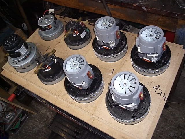 In the the main fan chamber the amount of vacuum being created means that some reinforcement is required. The angles were later fitted with studs and a neoprene sealing strip to seal the fan box access panel to the bench. 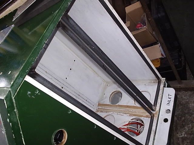 Every surface of the box must be painted to seal the surfaces to make sure that no air can be drawn through the material and give false readings. 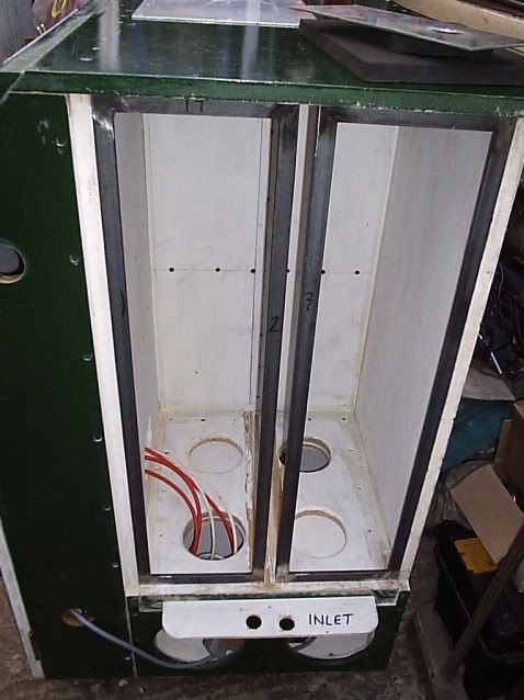 In the above photo you can also see the reversing slide valve that changes the direction of flow through the box. |
| |
|
|
|
|
|
May 18, 2016 22:00:01 GMT
|
|
Looking forward to understanding how this works.
|
| |
|
|
Darkspeed
Club Retro Rides Member
Posts: 4,882
Club RR Member Number: 39
|
|
May 18, 2016 22:12:42 GMT
|
Another showing the detail of the settling chambers the access ports - (bulkhead seals for boats) and the electrical area of the cabinet. 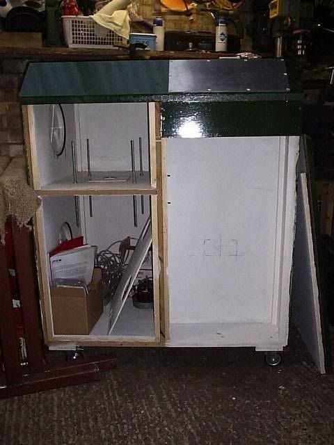 For a bit of a diversion Competition as to what car this chassis is from - and double points for the power of the engine it held developed. 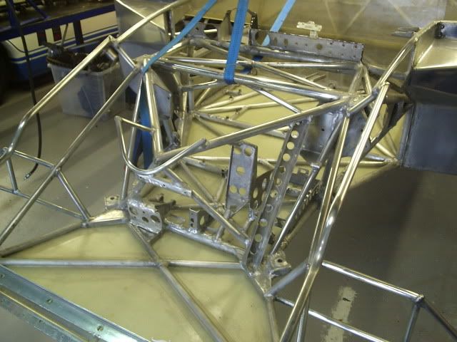 |
| |
|
|
|
|
|
|
|
This is the main motor board - I manged to find 4 quite powerful 2 stage motors which are the ones that I use in the main now that the other fours have been blanked off. They can flow a fair bit on their own and will easily take a well ported Rover V8 to the limit of the 36" sensor.  In the the main fan chamber the amount of vacuum being created means that some reinforcement is required. The angles were later fitted with studs and a neoprene sealing strip to seal the fan box access panel to the bench.  Every surface of the box must be painted to seal the surfaces to make sure that no air can be drawn through the material and give false readings.  In the above photo you can also see the reversing slide valve that changes the direction of flow through the box. Didnt The Darkspeedess get a little suspicious when her Henry's started disappearing at a rate of one a week?  Might not be able to pull the wool over the Darkspeetettes eyes when all their plasticine starts disappearing into your garage! |
| |
|
|
Darkspeed
Club Retro Rides Member
Posts: 4,882
Club RR Member Number: 39
|
|
|
|
Looking forward to understanding how this works. The principle is very simple - the link above will explain it better than I can and also shows - if really keen - the associated calculations to determine the rate of flow of what fluid is passing through the orifice. The orifice plate between the settling chambers has a carefully machined knife edge and for it's diameter it has a given Coefficient of Discharge. When thrown in a calculation with the physical properties of the fluid being measured a rate of flow is spat out. So very simply Pressure A on side A - compared with Pressure B on side B = Flow rate C . So all of that effort to build the box and wire all the motors and some other stuff is just to measure the air flow across that plate. - Accurately How that translates to what is going on with air flow through whatever you bolt on to the top of the bench will be along in a bit. This is what it looks like when you decide to check on David Vizard and the flow through an old Pinto 32/36 DGAV that has had the chokes bored out to 30mm and lots of little tricks like knife edged butterfly plates, slimmed down and knife edged auxiliary venturies and the like. 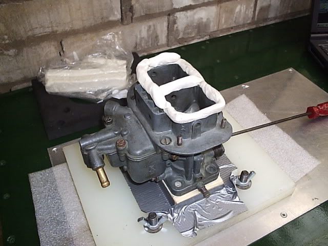 Complete with shot of my own purchased modelling clay - no product advertising here Mr @johnnybravo  - As for robbing clay and motors from the Darkspeederinoes and Mrs Darkspeed they are always willing to give support to the cause...... As long as I pay them - the mercenaries. |
| |
Last Edit: May 19, 2016 7:44:48 GMT by Darkspeed
|
|


 - Sometimes I forget the ' - I have not heard of any copyright issues with the Strato's bearing in mind that replicas have been in production since 1985


