|
|
|
|
|
|
Okay...let me just get my head around this. I was always curse word at maths, so I'll let you worry about that bit, but...
You take a bit of kit, head, carburettor, whatever, bolt it to your flowmeter and suck (and/or blow?) a known quantity of air through it. So far, so good? I assume you continue to modify and play with the piece until the flow is maximised, or restrictions are minimised? That is, to use your example, the values of A & B are as near equal as possible, indicating minimal restriction, which I assume is the object of the exercise.
If that's the case, then how do you know when to stop, i.e., the optimum values are returned and anything further will not improve matters, or may even be detrimental? Again, thinking about carburettors, without some restriction the thing won't work!
Sorry about the questions and tell me to pi55 off if you wish. It's just that watching something like this, coupled with your explanations, makes it all the clearer, rather than the somewhat dry delivery of Wiki.
|
| |
|
|
|
|
Darkspeed
Club Retro Rides Member
Posts: 4,882
Club RR Member Number: 39
|
|
|
|
Okay...let me just get my head around this. I was always curse word at maths, so I'll let you worry about that bit, but... You take a bit of kit, head, carburettor, whatever, bolt it to your flowmeter and suck (and/or blow?) a known quantity of air through it. So far, so good? I assume you continue to modify and play with the piece until the flow is maximised, or restrictions are minimised? That is, to use your example, the values of A & B are as near equal as possible, indicating minimal restriction, which I assume is the object of the exercise. If that's the case, then how do you know when to stop, i.e., the optimum values are returned and anything further will not improve matters, or may even be detrimental? Again, thinking about carburettors, without some restriction the thing won't work! Sorry about the questions and tell me to pi55 off if you wish. It's just that watching something like this, coupled with your explanations, makes it all the clearer, rather than the somewhat dry delivery of Wiki. Yes and No - gotta love that sort of answer  It will become a bit clearer as we progress but the essence is this. You hold a fixed depression within the bench - now what the hell is that? - knowing that mental illness is not a matter to take lightly I shall avoid any comments in poor taste - I could go a little more toward allowing a fat chick to sit in there - but again that's just avoiding making an explanation that is clear and easy to understand. With airflow, and many other measurements, we need some some fixed references to be able make the measurements meaningful and after a good few years of experimentation the industry as a whole came together and decided that a good figure for depression was 28" That is quite a miserable state or quite a fat chick so others use 10" of depression and then use a conversion factor......WTF is all that about I hear you mumble! Nature hates a Vacuum - a bit like Mrs Darkspeed in fact - Hence no issue if I rob the motors from them - and she, Mother nature, will do everything to fill it in (vacuum)if one occurs and she does this by trying to stuff said vacuum with air. What we do in our little flow bench is create a vacuum so we start off with the top of the bench completely sealed - no air flow - If there was a head on a fixture above the hole in the bench it would have the valve closed. We run the motors to achieve our fixed datum vacuum of 28". So there we are, valve closed no flow and a vacuum held in the bench at 28" - I shall explain that value and what it represents a little later. If I don't remind me. Our measurement of flow across our orifice at this stage is zero as we have the same pressure on both sides of the orifice. If we then open the valve in our cylinder head good old mother nature see's the vacuum we have made and stuffs a load of air through the gap to try and fill it. On it way to the motors that are creating that vacuum that air has to pass through our calibrated orifice and on it's way through we get to measure it. YAY! Now - We need to maintain a vacuum of 28" at all times so that we can have a fixed measurement datum, what we did by letting the air in through the inlet valve in the head is allow that pressure to be reduced - just a little - and we need to compensate for that by turning the speed up on the motors until we get our 28" back. We always need to have a that fixed depression in the bench no matter how far we open the valve in the head. It's that fixed orifice plate and fixed vacuum/depression on one side of it that allows us to accurately and repeatedly measure the flow. Each time we open the valve a little the flow will increase (hopefully), and we will need to wind the motors up to compensate for that loss in vacuum in response to that increase in flow. No doubt someone will mention floating depression benches - not interested it's not what I built and it's a subject for another thread if you so wish. I wanted a vernier gauge not a stick with notches on it. |
| |
Last Edit: May 19, 2016 10:23:30 GMT by Darkspeed
|
|
|
|
|
May 19, 2016 10:28:31 GMT
|
Darkspeed what can I say? Thanks very much for that. I think I'm getting the hang of it now, so I'll shut up and let you build the thing, whilst watching with great interest. Put it this way, I'm in the middle of doing a technical proposal, of which part is about rail demand forecasting. I'm seriously thinking of copying your words into it, as I understand them way better than those I'm sticking in there! Again, thanks. 
|
| |
Last Edit: May 19, 2016 10:28:54 GMT by georgeb
|
|
Darkspeed
Club Retro Rides Member
Posts: 4,882
Club RR Member Number: 39
|
|
May 19, 2016 12:17:19 GMT
|
No problem at all georgeb- and you are correct with your assumptions about when you stop. With cylinderhead development you generally try and stop before you reach the limits of the casting by finding a water way !! - With carbs - absolutely correct they rely on a pressure drop and pressure differentials within the body of the device to create further pressure differentials across jets and without that functionality no fuel can get drawn into the airstream - That, like cylinderhead porting and modification is an entire forum let alone thread on it's own so we will wind back a little from those subjects. The common ground with both is that eventually can get no further improvement in flow because you hit some sort of physical restriction that stops you - Once you have reached that point this is seen by no further increase in flow at that fixed 28" pressure differential or as you say for some reason the flow actually reduces. All I know about trains and demands was written by Rev W Awdry.  I will get on with the information on the build of it and then progress to the relevance of all this to this actual thread - There is one, honest. |
| |
|
|
|
|
|
May 19, 2016 18:48:42 GMT
|
|
Looks a great project, So in simple terms the intent is to measure the change in flow rate as you make changes while maintaining a constant pressure drop across the head?
I understand It's quite common to start with a scrap head and cut it up to determine the safe limits before you start, I know from past work even without going through the ports you can easily get into porosity problems.
|
| |
|
|
Darkspeed
Club Retro Rides Member
Posts: 4,882
Club RR Member Number: 39
|
|
May 19, 2016 19:16:13 GMT
|
Looks a great project, So in simple terms the intent is to measure the change in flow rate as you make changes while maintaining a constant pressure drop across the head? I understand It's quite common to start with a scrap head and cut it up to determine the safe limits before you start, I know from past work even without going through the ports you can easily get into porosity problems. The pressure has to be constant - and 28" was also found to provide a good velocity or air in the port to be able to make accurate tests on what sort of flow was present within the port. If the pressure was not constant the reading of flow would be going up and down with that pressure. Having constants and standards to make comparisons against is the basis of all measurement. I do love some of the old standards like grains and the history behind them. 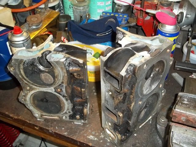 Porosity is a pain in the .... finding an inclusion that goes through into a water way is one of those testing moments especially on the last port of a head. |
| |
|
|
Darkspeed
Club Retro Rides Member
Posts: 4,882
Club RR Member Number: 39
|
|
May 19, 2016 19:57:57 GMT
|
So, electricians please look away now - functionality first - and this is the heart of the beast  Up top we have 5 variable speed motor controllers each is rated at 2400 watts if i remember correctly, and each is then mounted on a large heatsink even though they seldom get warm at the test pressures and flows that I run the bench at.  The little box in the bottom of the cab under the laptop power-supply is the clever part of the kit, the digital manometer. On a lot of older benches you will find vertical and inclined water column manometers. The trouble is that when you start pulling vacuums of near 40" that's quite a tall gauge and when you are trying to get good resolution on flow improvements the inclines also need to be carefully designed. It's also very easy to get sloppy and suck all the fluid out of the gauges and into the bench!! 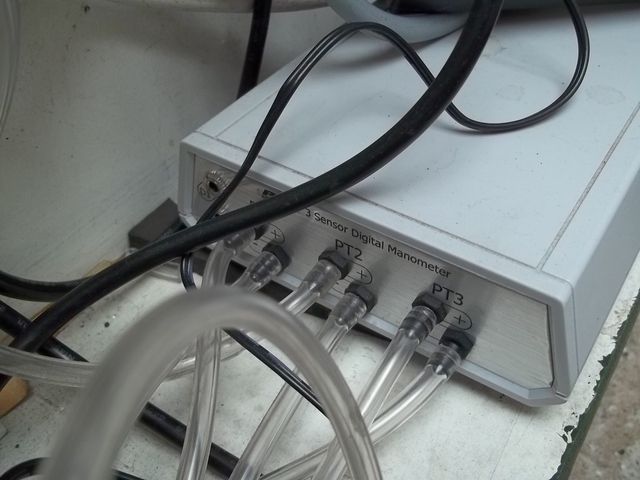 All these little air tubes connect to a couple of ported valves and the pressure tappings that pick up the pressures in the two chambers either side of the orifice. 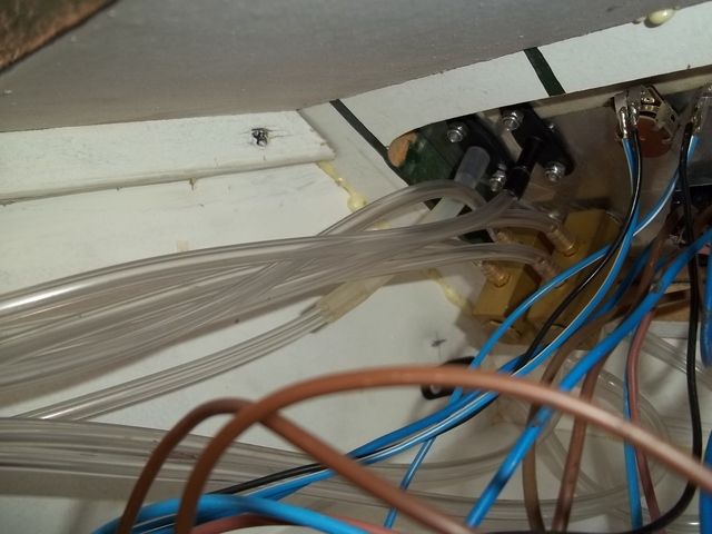 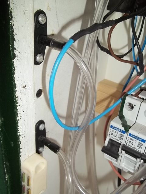 This is then all connected up to the control panel. 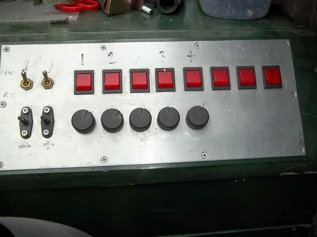 I really should invest in a label maker and stick some better labels on it. I keep promising myself to sand it all back and paint it correctly and make it look respectable - I will eventually Taking a peak down an adapter you can see the baffle over the orifice place - I made them clear so that I could fit lights in the chambers to reflect up the ports. The pro's will make the adapters from acrylic so that they can view what's happening. 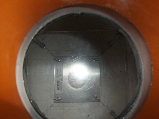 |
| |
|
|
Darkspeed
Club Retro Rides Member
Posts: 4,882
Club RR Member Number: 39
|
|
May 19, 2016 20:53:30 GMT
|
If you have gone through all the trouble of building a measuring device you really need to be able to test it's accuracy - no point having a ruler if it's calibrated differently to everyone else's ruler - These differences in units eventually end in issues and disappointment. I especially love the Mars Orbiter mission where an error was made with Metric and Imperial. What you need for repeatability is the ability to calibrate the bench against a datum and PTS produced a set of calibration plates derived from what were known as pass around plates. These were a set of plates that builders used to test the accuracy of benches and these original plates were then standardised into calibration plates.  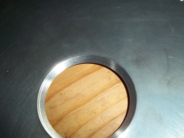 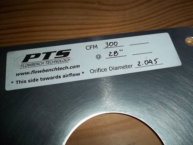 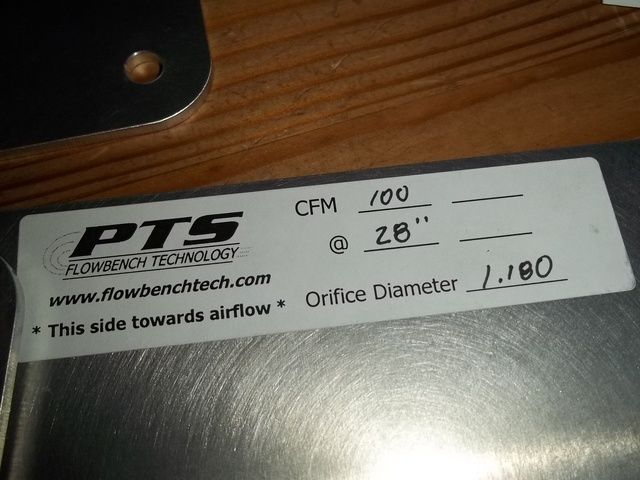 These plates have since been tested on other manufacturers plates to confirm accuracy across not only PTS benches but many other makes. Originally I ran the bench and calibrated it from a standard set of calibration figures and did not have it calibrated - when using the bench as a comparator and not an absolute measure calibration it is not 100% important but it's always nice to know that the figures you are reading actually have a place in the real world. When I eventually purchased a set of plates the bench was less than 2% out. |
| |
Last Edit: May 20, 2016 7:10:12 GMT by Darkspeed
|
|
Darkspeed
Club Retro Rides Member
Posts: 4,882
Club RR Member Number: 39
|
|
|
|
I was over at an old pals place yesterday giving him a hand with a few things as he has torn something or other in a bicep. Whilst there I collected an old 40DFA to replace the heavily modified 32/36 on the G31, which to my annoyance has recently decided to start to decompose. More annoyingly is the fact I had an equally modified 38DGAS which I am now kicking myself for selling. 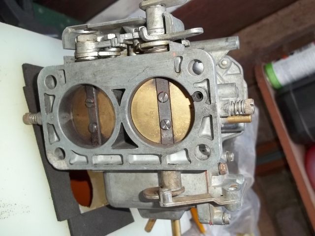 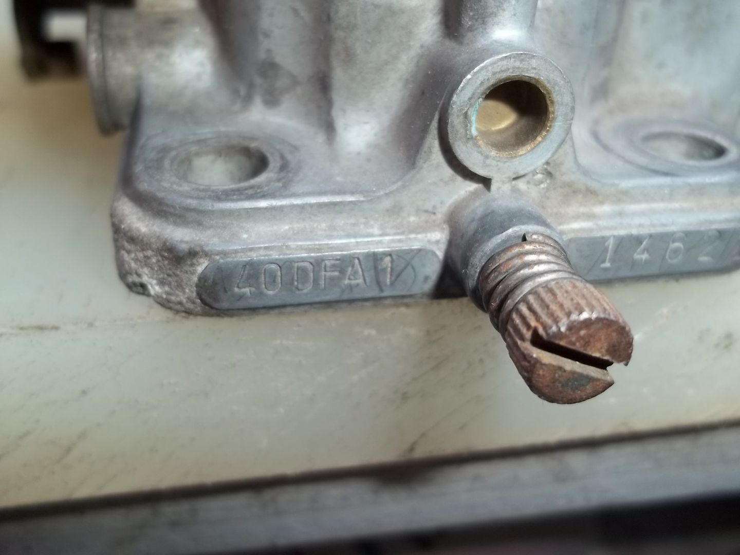 When I left, the back of the car had accumulated this little lot. 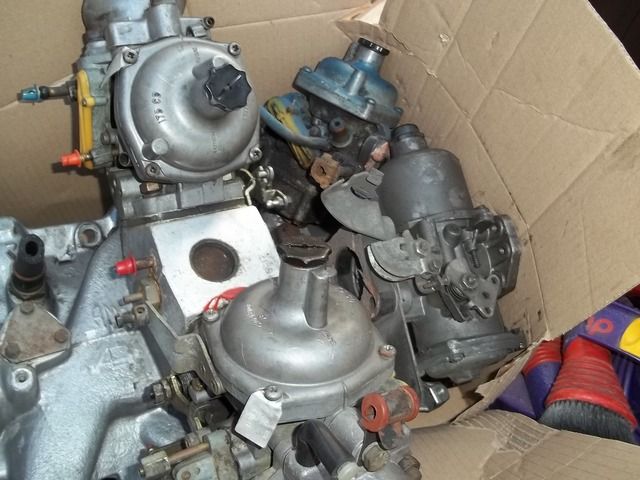 And a ported Vauxhall 1400 round port inlet manifold, throttle body and decompression plate that he had done for a customer for a turbo installation a good while ago for me to list on ebay for him! The Rover V8 manifold is only there to give up one of the Strombergs as a donor to match with the SU. I have been given them to settle a pub argument/discussion about what carb has the better flow potential, this "discussion" has been rumbling on for quite a while so I offered to stick both on the bench and settle it. The carbs will then go back to my mate Roy who will do a few little porting tricks on them and they will be back on the bench to see what the improvements are. For me I want to see the flow difference between my modified 32/36 and a standard 40DFA - a 32mm/36mm against a 40mm/40mm - no contest? I think it will be pretty close as the 32/36 has 30mm venturi bored into it and the 40DFA has the standard 28mm dia so how close will they be? The other test I have to do is a comparison on some Rover V8 big valves from two manufacturers 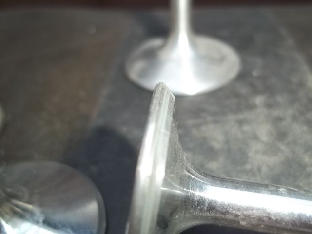 The Weber carb test should be pretty easy if I can find my old jig, the SU test will require me to manufacture some sort of mounting set up as I want to test these things horizontal flow. |
| |
Last Edit: May 22, 2016 7:34:20 GMT by Darkspeed
|
|
Anglia68
Posted a lot
   Powered By Boredom.
Posts: 2,050
|
|
May 22, 2016 13:42:28 GMT
|
|
This is all so far over my head that it's ridiculous but I'm still finding it very interesting and look forward to the comparison between the two Webers as I have a 32/36 on my crossflow and know where there's a 40DFA I could borrow.
|
| |
|
|
Darkspeed
Club Retro Rides Member
Posts: 4,882
Club RR Member Number: 39
|
|
May 22, 2016 16:29:25 GMT
|
Well it took a bit of time to get a suitable adapter made up but I got them on the bench - this was a very quick test as all it needs is a full flow comparison. 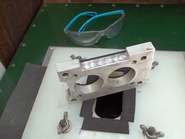 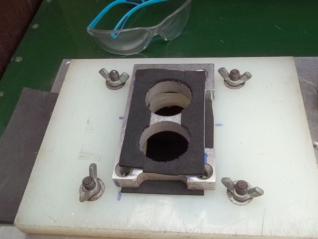 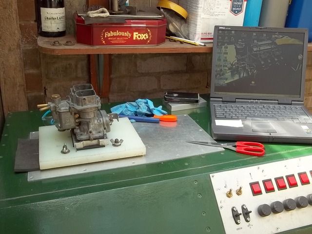 Modified 32/36 DGAV - 335 CFM @28" Standard 40 DFA - 400 CFM @28" 18% more flow out of the 40 DFA - to be honest I thought it would be a little closer than that so I thought maybe the 32mm choke really hurts the flow so I then did a quick test of the 36mm choke on its own. 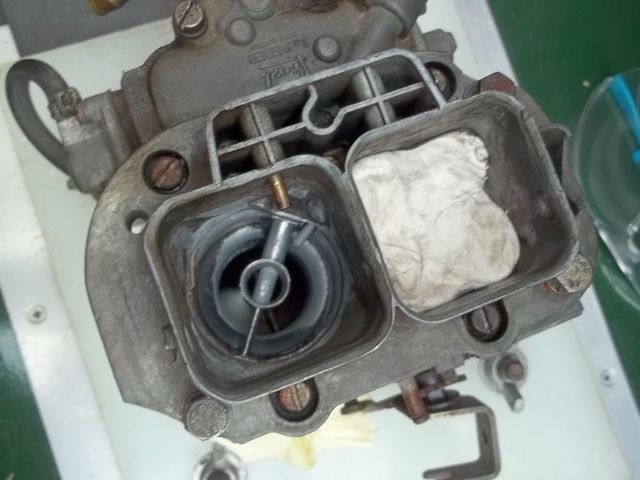 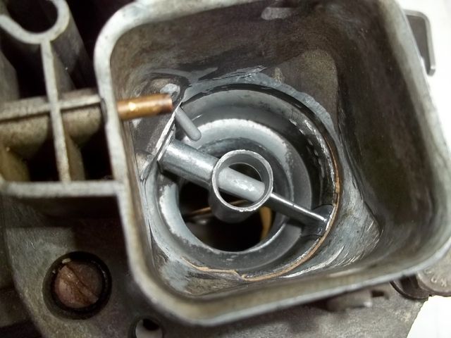 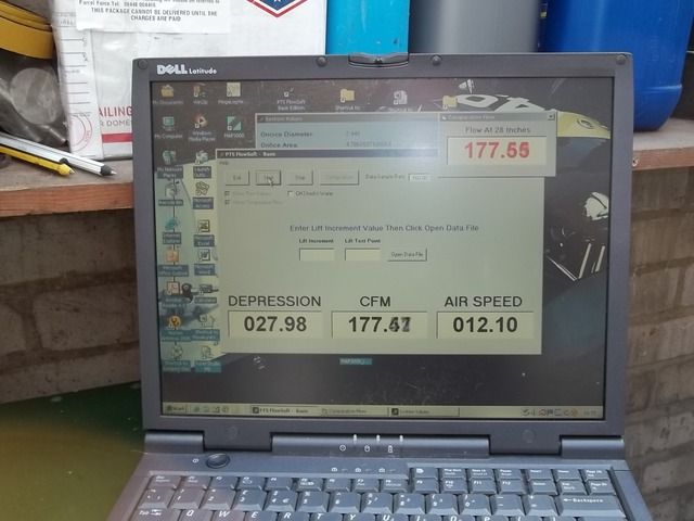 I did manage to get 179CFM out of the 36mm choke the 177 was due to the butterfly moving a little whilst I was taking the photo. On the 32mm choke only I measured 151 so 330 together which is close enough as there may be something going on with the airflow that allows a little more when both are open at the same time. One thing I can tell you is that it was incredibly noisy to test. |
| |
|
|
|
|
|
May 22, 2016 19:40:17 GMT
|
|
I have a 32/36 DGAV that I started to modify in the same way, then someone gave me a 38/38 DGAS which I still haven't fitted. I'm currently running a 32/32 DGV which I don't think has anywhere near enough flow for a lightly modified pinto but I drive like a grandpa so never really need the very high revs.
|
| |
1988 DUTTON LEGERRA MK1 - SPARES DONOR
1989 DUTTON LEGERRA MK2 - CURRENT PROJECT
1990 DUTTON LEGERRA ZS MK2
1990 DUTTON LEGERRA ZS MK2
DUTTON PHAETON S2 - Resting
DUTTON PHAETON S4 - Resting
DUTTON PHAETON S4 - PROJECT X
DUTTON SIERRA S2 - Resting
|
|
Darkspeed
Club Retro Rides Member
Posts: 4,882
Club RR Member Number: 39
|
|
May 22, 2016 20:00:25 GMT
|
I have a 32/36 DGAV that I started to modify in the same way, then someone gave me a 38/38 DGAS which I still haven't fitted. I'm currently running a 32/32 DGV which I don't think has anywhere near enough flow for a lightly modified pinto but I drive like a grandpa so never really need the very high revs. I would still be running the 32/36 on the Pinto in the G31 but the blooming casting has split at the inlet filter boss - I will keep an eye out on ebay for a 32/36 and if one comes up cheap I will repair this one as I only need to top of the carb. It flows almost as much as a 38 DGAS but still have the ability to sip along on the small choke due to the progressive linkage. The nice thing about the 38DGAS and the 40DFA is that the synchronous linkage does appear to give a lot more bottom end torque - However the DGAV was always easy to pass the MOT on emissions. The DGAS was always running rich on idle no matter what I did with idle jets and airs. Will see how it does with the DFA but clearly it has a fair bit more flow potential. I have found a few parts on the shed that will make up a jig to mount the SU and the Stromberg to, I will work on that during the week and see where I get with it. |
| |
|
|
Darkspeed
Club Retro Rides Member
Posts: 4,882
Club RR Member Number: 39
|
|
May 23, 2016 13:27:20 GMT
|
Useless information time - outside of this forum at least- but with a little relevance to this thread. Ever wondered what a 390, 450, 600 etc that Holley use for sizing 4 barrels actually means ? Well the figure that Holley put on the box is the air flow in CFM at a pressure differential of 1.5" Hg - Hg is Mercury and as it's a pretty heavy doohickey it takes a bit of suck to get it moving 1.5" up a tube - its the same as about of pressure required to move water 20.4" up a tube. Note - 2 Barrel Holleys are tested at 3"Hg so do not compare the two a 390 two barrel is not the same as a 390 4 barrel. converting Hg to Wg and flow at 20.4" to flow at 28" is actually quite straight forward. My flowbench operating program has a conversion built it - the picture below of me testing a modified 38DGAS shows three sets of figures. 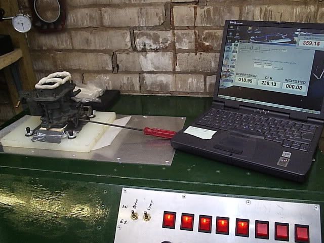 Depression - This is the actual measured pressure that the carb is seeing from the bench. Flow - This is the measured flowrate of air through the carb at that depression Ignore the lower right hand figure that channel is not being used. Up in the corner is a comparative flow figure that I have set to give an airflow reading that would be equivalent to 28" - This allows you to do a lot of testing at lower(and quieter) flows and you just need to whip it up to 28" actual to do a double check. At lots of benches just do not have the capacity to test over 10"wg. Back to the subject A 390 Holley flows 390 CFM at 20.4" wg which at 28" is - 457CFM If we want to compare our 400CFM 40 DFA Weber in Holley 4 barrel numbers that is 341CFM A 390 two barrel Holley - flows 323CFM at 28" - about the same as a stock 32/36 DGAV Hopefully this has also highlighted that without that crucial "wg figure - flow figures for anything are absolutely meaningless. |
| |
|
|
|
|
|
May 23, 2016 16:58:29 GMT
|
v interesting thanks for taking the time to post and explain  playing devils advocate, i realise engines are air pumps and that reducing pumping losses/ rstrictions = increase cylinder filling, or = engine being able to process more air. but my question, are there any instances where achieving the highest cfm possible at 28" does NOT translate to higher engine output? nuances with transient throttle angles, gas momentum, plenum's, pulse tuning with resonators, induction length etc etc ? or is it literally XXXCFM @ 28" will increase power over entire rev range? |
| |
|
|
Phil H
Posted a lot
  
Posts: 1,448
Club RR Member Number: 133
|
|
May 23, 2016 17:18:20 GMT
|
28" is pretty much what I gather in terms of what an engine can actually "suck". I'm no expert in these things although it's a compromise especially with carbs - you need a equal airflow through a restriction to allow fuel to be drawn through and still atomise it reasonably well. Bigger holes might make more power at the peak figure but at the expense of driveability for road usage yet you don't want the engine to be strangled - still a dark art to me  A most fascinating read though - I'm really enjoying reading your findings. |
| |
|
|
Darkspeed
Club Retro Rides Member
Posts: 4,882
Club RR Member Number: 39
|
|
May 23, 2016 17:57:19 GMT
|
v interesting thanks for taking the time to post and explain  playing devils advocate, i realise engines are air pumps and that reducing pumping losses/ rstrictions = increase cylinder filling, or = engine being able to process more air. but my question, are there any instances where achieving the highest cfm possible at 28" does NOT translate to higher engine output? nuances with transient throttle angles, gas momentum, plenum's, pulse tuning with resonators, induction length etc etc ? or is it literally XXXCFM @ 28" will increase power over entire rev range? [Michelle Dubois]Listen very carefully I shall say this only once[/Michelle Dubois] The power of an engine is 100% dependent on it's ability to consume air - To produce power you need to burn fuel to burn fuel you need Oxygen, air is 21% Oxygen or there abouts. If you can increase atmospheric Oxygen to 25% more power with the same flow - if you reduce it - Pikes Peak - less Oygen less power. You can test at any flow you please 10 /28 /40 /100 - 28" is just a standard for comparison purposes. Peak flow is not the be all and end all for a head. The important thing is the area under a flow graph - but as the biggest area is under the biggest number peak flow it is important but so is the flow throughout the valve lift, you modify and test to get the best flows at every mm of lift. What happens after the head in the induction or exhaust etc. will always effect power. If you just fit a load of poorly matched odds and ends even though you have a great head that poor choice of ancillaries may well lead to less power. However the head will still have the ability to produce more power with the right bits fitted. Again more air equals more power you cannot produce more power with less air(Oxygen)- simple It's a system, the head/valve is just part of that system but it's a key part and where you start when you looking to unlock the full potential of an engine. You then move to match every other part of that system to it. Could there be an instance where high peak flow does not increase or reduces power - Yes if you developed a head for higher flow and screwed up the low lift flows and then fitted a cam that only lifted the valve as high as those low lift flow numbers the engine would have less power. Strap in a high lift cam that makes benefit from those high lift numbers and you are back in the game. However if your competitor improved flow from right off the seat to the peak lift of the valve - you are coming in second. Everything matters in the system but it's all about air flow and the ability to cram as much air in the cylinder in those few milliseconds you have to do it. Measuring at 28" does not always tell the full story - there are instances where at greater flows and port velocity turbulance occurs that will destroy flow and no doubt that could happen in the engine - That's when things get really complicated with mapping the air velocity in the port so that you reduce the chance of turbulance and break away...... Again, want to dig into this - Speedtalk is your friend. |
| |
|
|
Darkspeed
Club Retro Rides Member
Posts: 4,882
Club RR Member Number: 39
|
|
May 23, 2016 18:39:15 GMT
|
28" is pretty much what I gather in terms of what an engine can actually "suck". I'm no expert in these things although it's a compromise especially with carbs - you need a equal airflow through a restriction to allow fuel to be drawn through and still atomise it reasonably well. Bigger holes might make more power at the peak figure but at the expense of driveability for road usage yet you don't want the engine to be strangled - still a dark art to me  A most fascinating read though - I'm really enjoying reading your findings. Huge subject and I just mess about mostly making noise but you do get to find out some interesting things The reason I am testing a couple of valves is that the tiny back cut on the valve on the left improved low lift flow 15% at one lift point. - You will find that unmodified valve in the greater majority of Stage 3 Rover V8 heads - Peak flow may well be very close, but all the way to .300" this modification will flow more. Another manufacturer who has a slightly different shape valve (almost like my mod  ) is not used very often as their valve is that bit more expensive.. 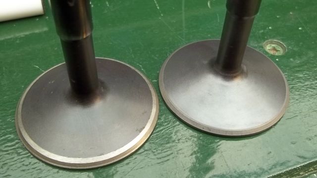 Must really get on with that SU/Stron set-up - after I mow the Lawn  |
| |
|
|
|
|
|
May 23, 2016 19:57:23 GMT
|
|
A great read - and I am particularly interested in the RV8/DGAS links as I ran those in my drag racing life - but all done empirically I'm ashamed to say!
|
| |
|
|
Darkspeed
Club Retro Rides Member
Posts: 4,882
Club RR Member Number: 39
|
|
May 23, 2016 20:43:33 GMT
|
A great read - and I am particularly interested in the RV8/DGAS links as I ran those in my drag racing life - but all done empirically I'm ashamed to say! This will look sort of familar then 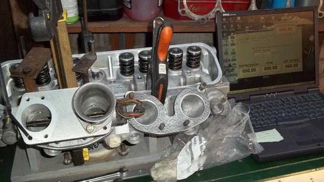 This is me doing a no valve test on a 45mm thottle body to see what the losses were through the induction from bell mouth to valve seat. Nothing  The induction does not create any restriction to flow. The throat is the weak link - I hoped this would be the case as the porting and matching is worthy of a man that has probably ported a thousand Rover V8 heads in his career. (Not myself) And there is only so much flow you can get out of the RV8 medium valves.  As for being ashamed of actually getting out there and doing it by trial and error -  That is often the most enjoyable, even with the " What the fox went wrong there!!?? moments.  |
| |
|
|


