|
|
|
|
|
|
IVA regs deal with what are, basically, new cars so have to comply with a lot of the latest regs.
Construction and Use regs are not the same as MOT rules. My MOT station checked and they are happy with the polycarbonate windscreen on my age of car. I could argue that a polycarbonate screen was fitted by the builder back in 1967 (it was sold as a kit back in the day to avoid purchase tax) :-) The trade name Lexan originated in 1960.
At the end of the day, it is an item that is easy to replace if necessary.
|
| |
|
|
|
|
|
|
|
Mar 16, 2019 13:07:15 GMT
|
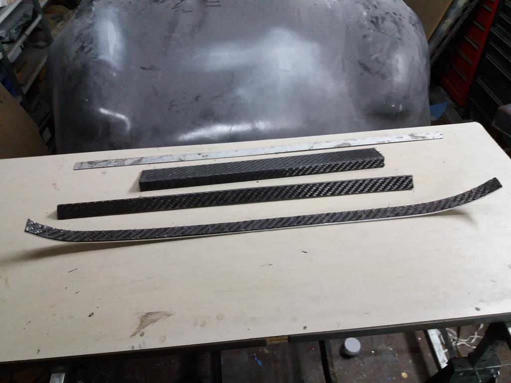
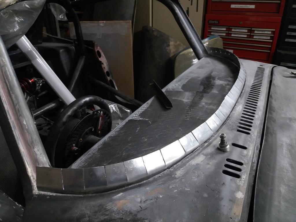
Are these an off the shelf item then ? no heaty heaty bendy bendy ? Do the trims have any other function other than to look pretty, is this a bit of selective application of the mantra or do they come off once the screen is bonded in ? Getting close to looking like a car and not a project ! James If you mean the polycarbonate screens, yes they are off the shelf. The shelf being at the warehouse of the polycarbonate sheet stockists :-) I was paraphrasing the famous sculptor who said everything he makes is already in the rock, he just has to remove the excess rock :-) I am prepared to thermoform the polycarbonate if required, either localised heat or using my curing oven for an overall heat treatment. The aluminium 'trims' are thickness guides so I can build up the bodywork to the same height as the screen and give me a clean and sharp edge. They will be removed before I start to cut the screen to fit. The extra filler adds a little weight but reduces aero drag, so I think that the mantra is still intact :-) |
| |
Last Edit: Mar 16, 2019 14:55:04 GMT by nalesutol
|
|
|
|
|
|
|
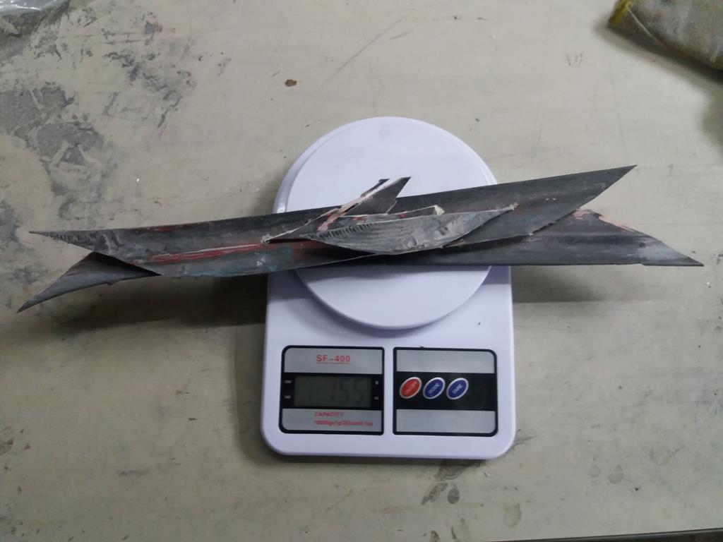
Replacement polycarbonate (in orange packing) front and rear screens arrived today. However, the edges are protected by polycarbonate so that will have to be removed before they can be fitted.  |
| |
Last Edit: Mar 16, 2019 9:32:35 GMT by nalesutol
|
|
|
|
|
Mar 13, 2019 19:31:03 GMT
|
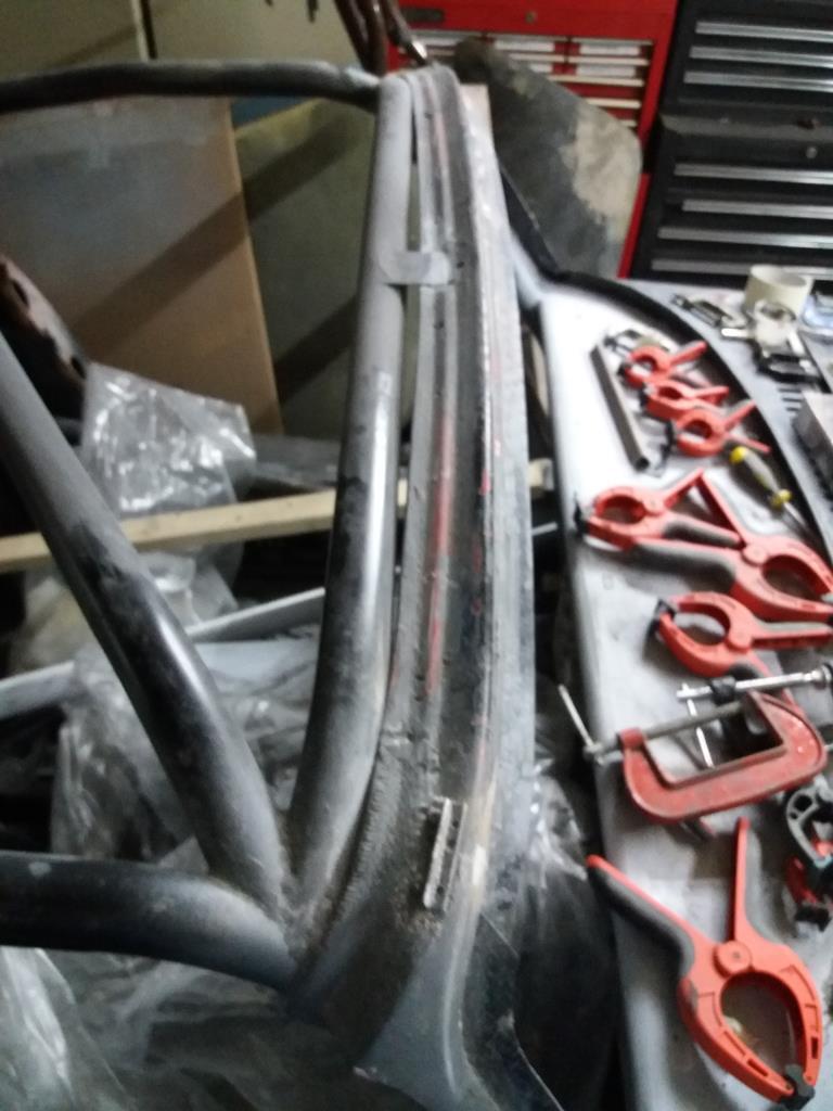
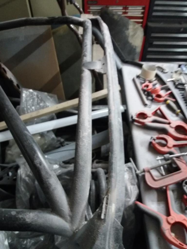
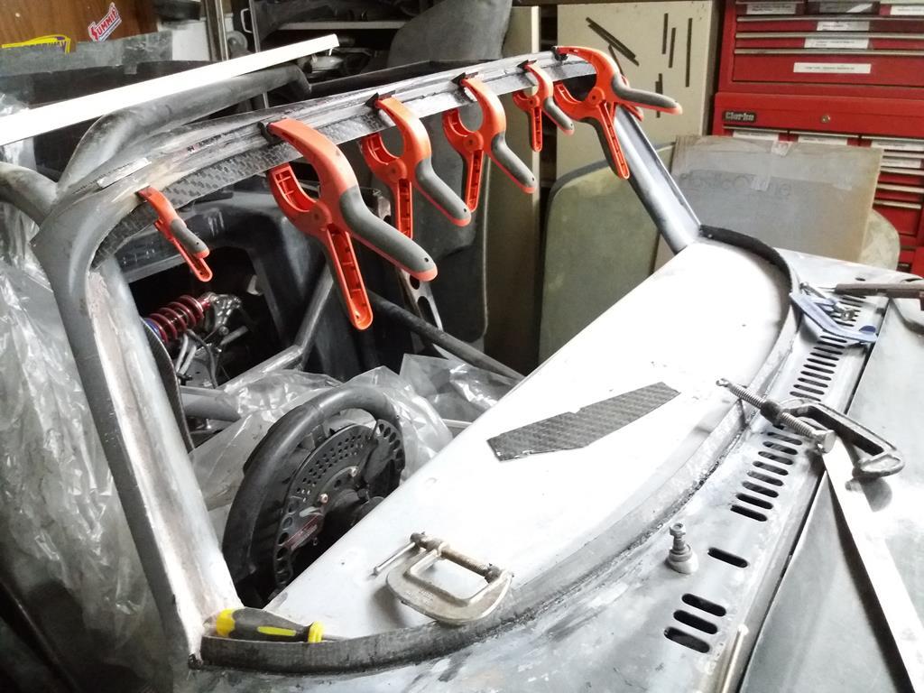
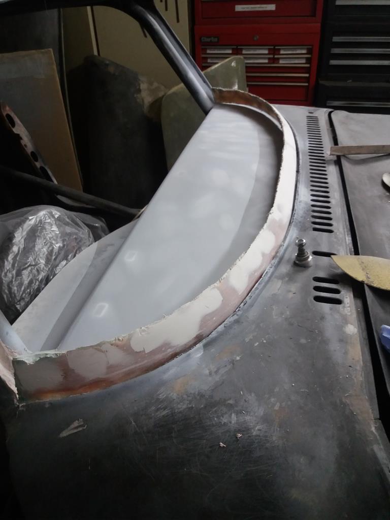
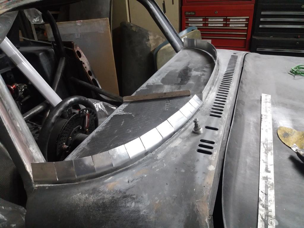
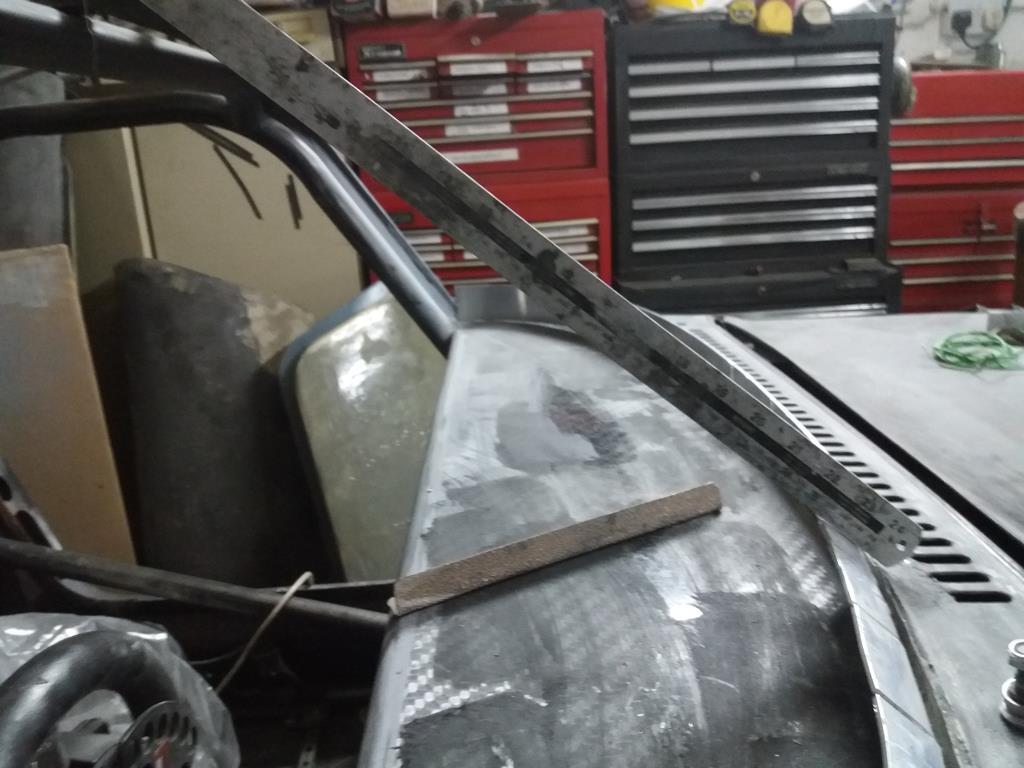
The front and rear screens are going to sit flush with the body. To that end I need to tidy up the edge of the recesses. To do this I decided to use aluminium strip to form the shuttering for the carbon filament filler. Couldn't find the right size strip so I bought one that was wide enough to make two pieces and sliced it with my band saw. Once you fork out for these toys they very quickly pay for themselves :-)  Next task was to shape the strips to conform to the body contours. As the bottom strip had to be twisted in along all three axes this was the trickiest one. After an hour of trial and error I had it shaped to my satisfaction. The trick was to cut it in two and deal with each side separately. The sides and top were easy in comparison. Next job is to fill and shape the bodywork to tie into these strips (started on the bottom edge). Hopefully they will pull off without too much trouble as they are held on with glue gun glue and treated with release agent.  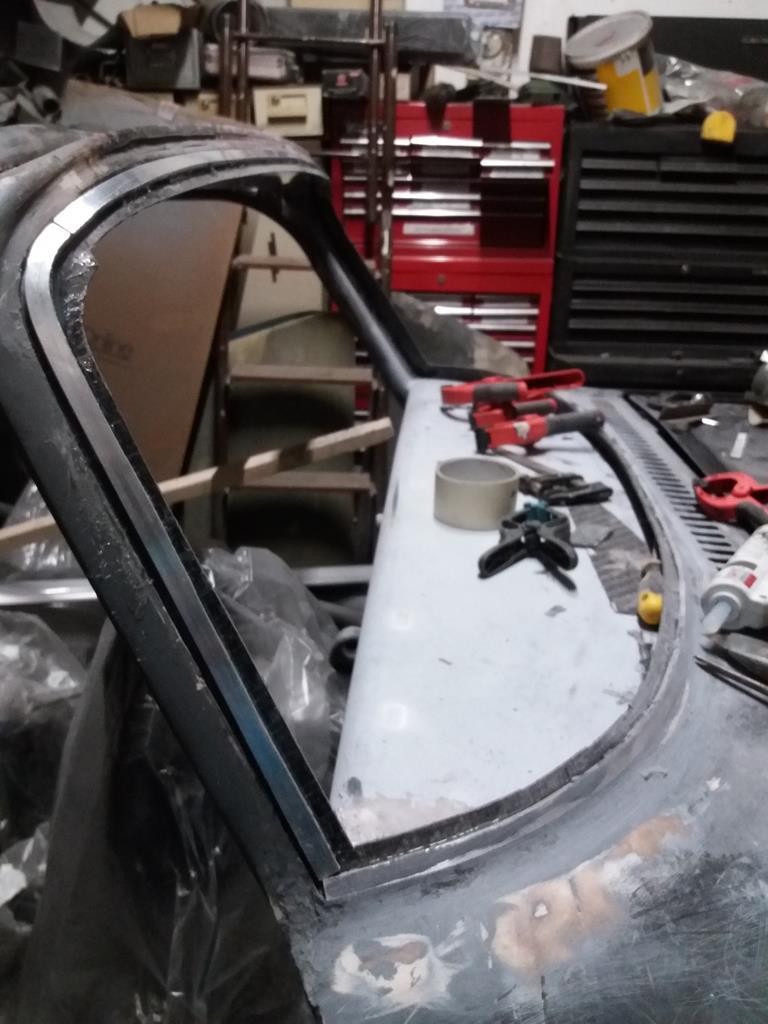 |
| |
Last Edit: Mar 13, 2019 20:56:32 GMT by nalesutol
|
|
|
|
|
Mar 12, 2019 14:50:21 GMT
|
One of a pair of air curtains. 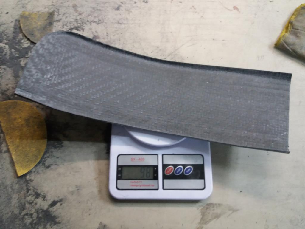 |
| |
|
|
|
|
|
Mar 12, 2019 14:48:38 GMT
|
|
|
| |
Last Edit: Mar 12, 2019 14:49:22 GMT by nalesutol
|
|
|
|
|
Mar 10, 2019 22:12:28 GMT
|
This is what happens to the teeth of a standard band saw blade when it has cut a lot of carbon fibre. 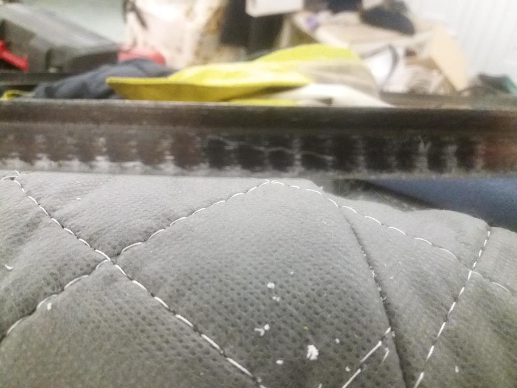 |
| |
|
|
|
|
|
Mar 10, 2019 19:08:13 GMT
|
Windscreen lip extensions glued on, next task is to trim and then attempt to make the Lexan screen. 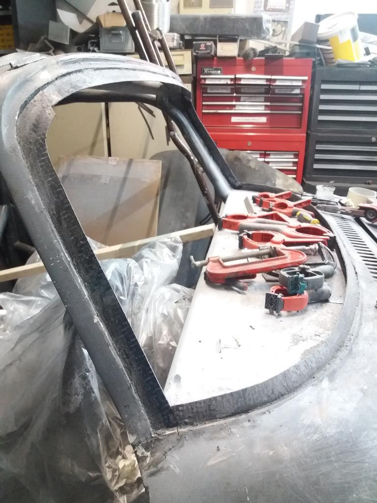 |
| |
|
|
|
|
|
|
|
|
|
| |
Last Edit: Mar 9, 2019 20:54:33 GMT by nalesutol
|
|
|
|
|
|
|
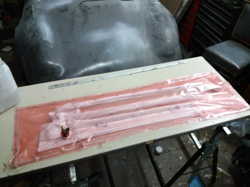
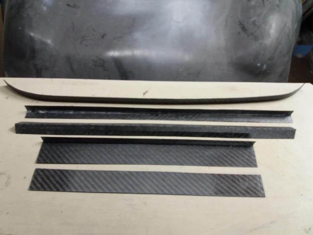
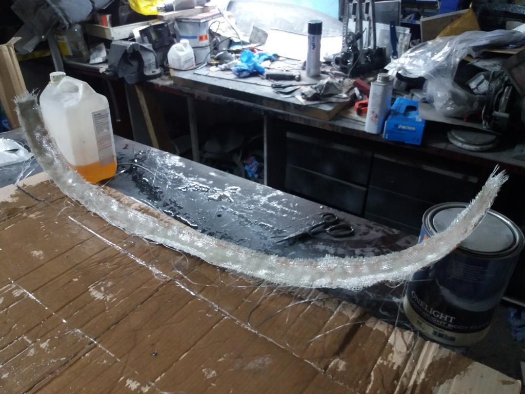
Pattern for top strip of windscreen support made. As this has no cuts like the bottom pattern it will also act as the mould. 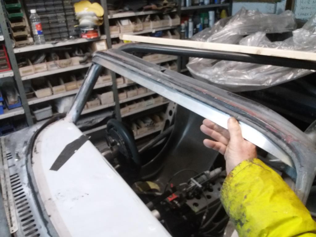 |
| |
|
|
|
|
|
|
|
Pattern - Mould - Part. 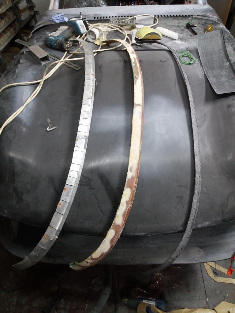 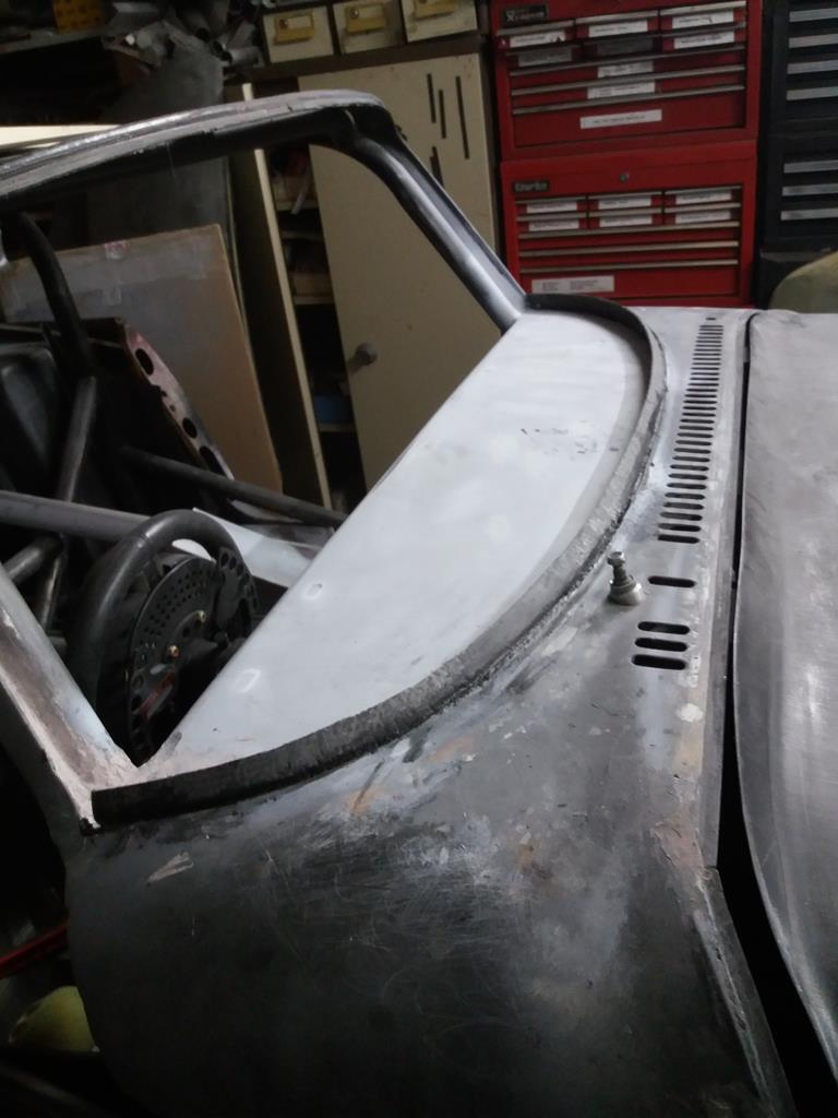 |
| |
|
|
|
|
|
|
|
Its been 30 years since I studied it at university, but one thing I remember is that the transition between turbulent and lamimar flow has a significant effect and most of the theory goes out of the window if you lose laminar flow, tiny details can affect this such as the radius of a corner. Absolutely, air doesn't like changing direction so the bigger the radius the better. However, at the rear you need sharp edges so the air car fly off and not curve down behind the car. My rear end has lovely curves so these need to be attended to :-) |
| |
|
|
|
|
|
|
|
With regards to sharp edges vs bell-mouthed intakes my understanding is that it depends on the condition of the air being taken in. Within an induction system, like an intake trumpet in an enclosure, the air is flowing as a result of pressure difference. Where as a 'ram air' intake* or a duct to something like brake cooling or a radiator is trying to capture an existing flow. They're quite different circumstances and need thinking about differently. When the air's being moved by a pressure difference all the air around it is fair game, including the air to the side of and slightly behind the intake, as the pressure difference is capable of causing that air to rush towards the inlet. The best entrance design is the one that allows and smooths this flow, usually a typical bellmouth (just as nalesutol shows on his turbos intake trumpet). Things change when your talking about trying to capture existing flow, rather than create new flow. In this instance we're trying to allow the air to maintain its inertia the best we can, and a bell mouth can cause a pile-up of air trying to enter it as its cross section decreases. Getting air to flow through it requires work (in the form of increased pressure or velocity) and will be at the cost of some air flow, if the goal is airflow it's probably more efficient to simple 'cut' a section of air out of the existing flow and allow it to continue as unimpeded as possible. *Which design is most efficient is situational, and in the instance of a 'ram air' intake it would depend on whether the outside air's flow is great enough to keep up with the engines needs. Looking at bikes and f1 cars I'd be guessing that their speed relative to their engines air consumption is enough that the designers have deemed the 'cutting' method to be the best bet, but the f1 cars look like they're on the boarder as their intakes appear to be a compromise between the two in a lot of cases. Obviously things will change even more when you put the entrance somewhere without free flow, like above a splitter where there may actually be a high pressure to 'create' flow. Or if a brake or radiator duct has some sort of extraction an exit into a low pressure region. I hope that makes some sense. I'm definitely no aerodynamicist, so this is just my understanding, but it makes sense in my head, and appears to match existing designs that real aerodynamicists will have spent time on. I'm absolutely loving the Lotus by the way. Your mentality towards it all and the carbon work is awesome. Can't find fault with this :-) Air flow is often counter-intuitive. Many beginners can't get their heads around Bernoulli's principle that states that an increase in the speed of a fluid occurs simultaneously with a decrease in pressure or a decrease in the fluid's potential energy. And Vice Versa. This lack of understanding is one reason why so many hood scoops are incorrectly positioned and why lifting the rear of the bonnet won't necessarily result in engine bay cooling :-) Thanks for the compliment, I try my best and post both successes and failures. |
| |
Last Edit: Mar 3, 2019 11:52:48 GMT by nalesutol
|
|
|
|
|
|
|
Air scoops can't ram air into an engine. The engine will only pull in what it can using the vacuum caused by the pistons. What scoops do is help to eliminate any restriction to the air flow so there is no pressure drop in the inlet track which would reduce the amount of air available to the engine. The only way to get more air into an engine than what it can pull in on its own is some kind of supercharging. Ouch....Vacuums cannot pull, it is the air at atmospheric pressure that pushes into the low pressure area.(Alert - Pedant Phil).  And I thought that I was pedantic! Of course vacuums can't pull, they suck :-) The point I was trying to make is that the only way to get more air into an engine is to increase its density, simply increasing a fluid's velocity won't work as this reduces its pressure. |
| |
|
|
|
|
|
|
|
Great build ... really enjoying following this . Can I ask ( sticks head above parapet) are polycarbonate windscreens 'Road Legal' ? I understood them to be race only ... Just asking  For my age of car (1967), no problem. Can't answer for any other year. I think newer cars have to have some sort of BS number on the glass: MOT Manual Class 5 glazing Vehicles first used from 1 June 1978 must have: windscreens and windows on either side of the driver’s seat made from safety glass all other windows made from safety glass or safety glazing Safety glass can be identified by one of the following markings: BS 857 BS 5282 – but not acceptable on vehicles first used on or after 1 April 1985 TP GS or TP GSE – but not acceptable on vehicles first used on or after 1 October 1986 BS AU 178 an ‘E’ mark (including the number 43R) an ‘e’ mark followed by a number, such as e11, inside a square Safety glazing means material other than glass constructed or treated not fly into fragments that would cause severe cuts if it's fractured. There is no marking requirement for safety glazing. |
| |
|
|
|
|
|
|
|
Feb 28, 2019 23:39:44 GMT
|
|
|
| |
|
|
|
|
|
Feb 28, 2019 21:35:21 GMT
|
Just out of curiosity have you kept a record of how much epoxy and carbon sheet you have used in this car so far? A future car project for me will involve a lot of f/glass and epoxy but as I'll be a complete newbie I have no idea on how much quantity one might get through. I dread to think :-) Most of the carbon is prepreg so not a huge amount of tinned resin. You can work out a fair guess based on the area you plan to make plus the number of layers you plan to use and add 10% for wastage if using carbon cloth and resin but only 5% if using prepreg. Then probably double it because you will forgotten some things and will find more stuff to make :-) If using cloth and resin then the rule of thumb is the amount of resin used is equal to the weight of the carbon cloth. For example. 1 m2 of 250gm/m2 in 4 layers (making the arithmetic simple :-) ) equals 1kg of cloth so 1kg of resin would be required. Once you become more experienced you can start to reduce the resin content but you have to make sure EVERY carbon strand is saturated with resin. Using fibreglass is similar, the cloth must be fully saturated otherwise strength and appearance is compromised. |
| |
Last Edit: Feb 28, 2019 21:36:00 GMT by nalesutol
|
|
|
|
|
Feb 28, 2019 21:25:03 GMT
|
|
Air scoops can't ram air into an engine. The engine will only pull in what it can using the vacuum caused by the pistons. What scoops do is help to eliminate any restriction to the air flow so there is no pressure drop in the inlet track which would reduce the amount of air available to the engine. The only way to get more air into an engine than what it can pull in on its own is some kind of supercharging.
|
| |
|
|
|
|
|
Feb 28, 2019 10:00:50 GMT
|
Air actually acts as a fluid, not surprising really as that is what it is. Photo shows the trumpet that will be fitted to the turbo. As can be seen the tube from the filter is larger than the trumpet. This allow for air to be drawn in from both behind and the side of the trumpet, allowing more air to be drawn in. I hasten to add that this was a work in progress at the time and the finish is a little more refined now :-) 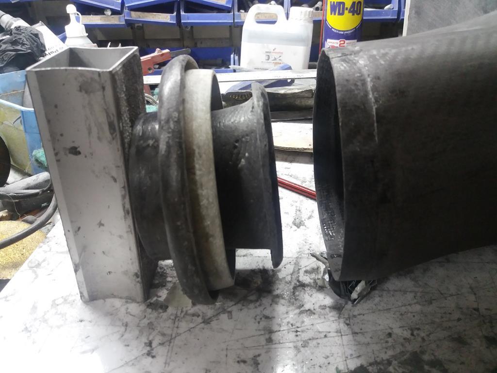 |
| |
Last Edit: Feb 28, 2019 12:15:06 GMT by nalesutol
|
|


