|
|
|
Jan 22, 2011 16:01:44 GMT
|
|
Renault 19? I think you mean R16 since the 19 uses a transverse box.
Perhaps a modern Audi/VW gearbox (80/A4/Passat) can be made to fit, if my thinking is right that these transaxle fit reverse rotation of the engine.
|
| |
 Click picture for more |
|
|
|
Carsie
Part of things
 
Posts: 127
|
|
Jan 22, 2011 21:15:36 GMT
|
Wow! I wish I had your skills and talents - loving the build and it's journey  This is definitely flagged as one of my favourites I took this pic from a website forum.lazzaroni.no/viewforum.php?f=3I think it's Norwegian or Swedish and spent hour trawling through it - they seem like a good bunch of lads, if only I understood a blinking word of what they were saying lol! By the way I think I found Seth's Hillman Est on there as well ;D  850%20Special2 850%20Special2 by carsie.100, on Flickr |
| |
|
|
|
|
|
|
|
A little stumble backwards. I tried to coat the pistons. These are just a used set of 903 pistons I picked up from another fiat owner. Sandblasted and washed in acetone, scrubbed with a toothbrush until they couldn't be any cleaner.  The directions said to only spray on enough ceramic coating to leave a thin wet layer. Well that didn't seem like enough at all so I laid a little more on. It sure looked great  So I put it in the oven and after an hour...disaster  Did a bit of googling and found out that I just laid it on too thick. I can sandblast it off and try again but the dry film lubricant that was shipped to me came as a powder and it was supposed to be a liquid. Not sure if it dried out in transport (would it be a powder then?) or if I should try to mix it with a solvent. Waiting on response from the seller. The DFL should go on before the ceramic so I am just waiting now. So I started in on the mods to the block. The 850 engines use a centrifugal oil filter system and lack a pressurized center main bearing. Since the 60's people have been modifying them to use an external oil filter element and to pressurize the center main. There is not a lot of info out there on how to do this anymore. I am going off scans of photocopies made in the 80's, spanish forum posts with dead images and the info over at scuderia topolino. Turns out that once you look at everything assembled it really is simple. start at the center main. Install a late 903 bearing with the appropriate oiling hole and mark its position.  Drill into the bolt hole down at an angle  Then go to the outside of the block and remove the plug from the oil galley. that oil passageway runs pressurized oil from the pump to the cam bearings and the upper end of the motor. The hole I need to extend is already drilled most of the way so I just need to extend it an inch to meet up with the other side of that bolt hole on the center main.  So, Now the oil will come from the pump and get sent out the side of the block where the oil pressure relief valve use to be (the valve and its hole are in the lower right of that pic above) through a fitting I have yet to decide on, through a hose pipe to an oil filter on the firewall and back in to the motor via that drilled out plug. That will pressurize the 3 main bearings and everything else. But this leaves me with no pressure relief. I probably should just import an oil pump for any of the modern fiat 903 motors but I have a good pump so....  Take the line that used to run the oil to the crankshaft and turn one end into a plug and on the other end weld the pressure relief valve on. Now I just need to tap the side of the block for whatever fittings I end up with and fill in the hole on the end of the crankshaft. Just one or two more things before I can send the block out to be bored. |
| |
|
|
|
|
|
|
|
It turns out I ordered the wrong product. The proper DFL is on its way. The powder is intended to be buffed into freshly honed cylinders. The next mod to the block is drilling out the 9mm head bolt threads and tap them to 7/16-14. By ordering a set of ARP head bolts for a ford 302 I not only save over $70 versus buying fiat specific 9mm ARP hardware from a fiat supplier, but I get to go oversize to increase the clamping pressure. The Fiat uses 9 long bolts and one short one hidden in the intake well. Small block Fords use 10 long and 10 short. Sure I will not use half of them but I still save quite a bit. The 9mm fiat hardware has a max torque spec of 36ft/lbs and I go dangerously past that to 50. The 7/16 ARP hardware can safely take about 80ft/lbs. That should help me stop popping headgaskets  The sqare insured I wasn't tapping at an angle  The side of the block and the old pressure relief housing were drilled and tapped to 3/8" pipe thread for easy adaptation to AN hoses.  Yep I blew another one monday. My boost controller drifted up to 15psi due to an incorrectly set lock nut. |
| |
|
|
|
|
|
Jan 27, 2011 13:13:30 GMT
|
I can't belive that I have missed this thread, so much awesome DIY stuff going on! I am at a very similar stage with my imp, the engine has become too much for the gearbox to handle, so I need to find a solution, however the orientation makes it very difficult. It has made me walk away from the project for a few months, just too much stress  This thread is making me perk up though, nice to see someone else overcoming similar problems. Keep up the sterling work, and I will get back on mine  J |
| |
|
|
|
|
|
Jan 27, 2011 16:48:38 GMT
|
|
You better get back on your imp. That thing is an inspiration to all us little rear engine car folks.
|
| |
|
|
|
|
|
Jan 27, 2011 22:38:42 GMT
|
Thanks Ditch! There are plans afoot, another gearbox to get going with and some more minor engine mods  |
| |
|
|
|
|
|
|
|
Started in on the cylinder head today. I chucked it in the mill to deshroud the intake valves and take a cut on the mating surface.  I am not sure how much good this will actually do in a boosted application but I have been wanting to do it since I read the Faza fiat 850 competition guide. It is also one of the differences on the Autobianchi A112 Abarth head Pilfered pic of a stock fiat head and the A112 abarth head 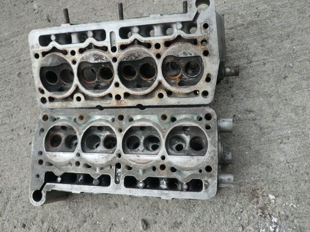 Not sure if it will do me any good but it was easy enough and if nothing else it will lower the compression ratio a little bit. I obviously need to do a fair bit of blending and shaping in the combustion chambers. After that I have a friend who will perform the 3 angle valve job for me. Then I can ceramic coat them. |
| |
|
|
|
|
|
Jan 30, 2011 15:58:05 GMT
|
|
Very neat indeed, I did mine in a similar fashion but using the far less accurate dremel technique!
|
| |
|
|
|
|
|
|
|
I don't know what it is about these fiat motors but of the 6 I have torn down all but one have had some sort of WTF going on in at least one cylinder. This head had it in two! but it was also the best one I have lying about. Not sure if it is because the intake is a very effective funnel and that any time the carb is off it attracts loose nuts and washers like a magnet. This is the underside of two cylinders after the first light cut on the mill.  Cleaned it as best as possible and fired up the TIG and drop filled all the bits that needed it 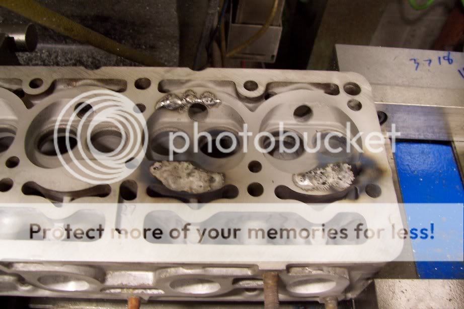 Back into the mill and attacked with the flycutter 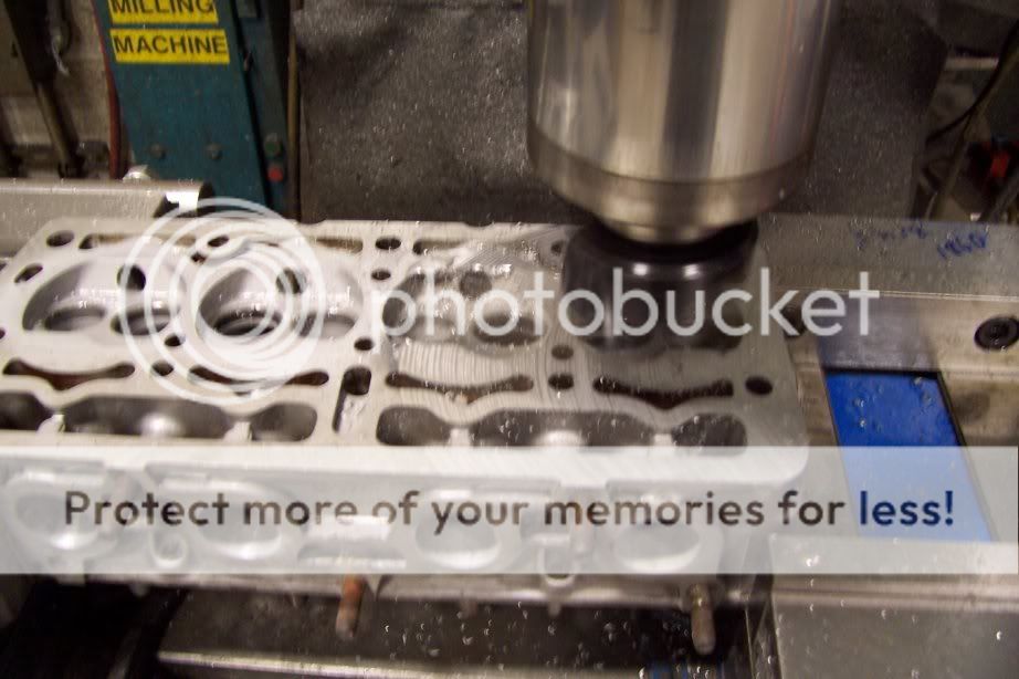 And off  Now off to my buddy to see if these valve seats are salvageable. They look pretty rough. The weather was unseasonably stunning today. Sunny and high 50's.....in january fer chrisakes! I took advantage and hit the driveway with some bits I had made last week. New swaybar end links!  The original rubber was totally perished. It was a quick job.  Lets hope it does some good. |
| |
|
|
|
|
|
|
|
|
|
Success!  Skirts coated in dry film lubricant, tops in ceramic. Cured in the oven at 350 for 2 hours and no bubbling. Not perfect. I might redo them but these are technically ready to install after buffing the DFL with scotchbrite. A few weeks with the moustach and I am warming to it but I still think I prefer it without  Still haven't taken the block to the machine shop. Waiting on some funds to roll in. Loaned out my MIG so I can't shave the rest of the holes.... Just taking it slow for the time being. |
| |
|
|
s123
Part of things
 
Posts: 45
|
|
|
|
|
Fantastic build! I want one of these.
|
| |
_______________________________________
Life's more painless for the brainless.
|
|
vegar
Part of things
 
Posts: 38
|
|
|
|
Wow! I took this pic from a website forum.lazzaroni.no/viewforum.php?f=3I think it's Norwegian or Swedish and spent hour trawling through it - they seem like a good bunch of lads, if only I understood a blinking word of what they were saying lol! By the way I think I found Seth's Hillman Est on there as well ;D  850%20Special2 850%20Special2 by carsie.100, on Flickr Its Norwegian, but the ad is actually Danish  |
| |
|
|
vegar
Part of things
 
Posts: 38
|
|
|
|
This is just a fantastic tread. I am very curius about the DIY coating and how that works out  |
| |
|
|
|
|
|
|
|
Time to learn a new skill. I have been thinking about the valves a lot lately. Wondering just what all is involved in a simple 3 angle valve job and how difficult the actual act is and what equipment is neccesary. I have a co-worker who is some kind of idiot savant/mechanical genius/epic bodger. In his current list of cars is a Vespa 400, 53 Studebaker pickup, 78 Corvette, a 50's Studebaker Hawk and a 69 Camaro. He also collects antique tractors and all sorts of other vintage things. If anyone had the info I needed it would be him. I asked about valve seat grinding and the next day he showed up at work with this box  This awesome 1950's cantilever box is stuffed full with equally old valve seat grinding tools. 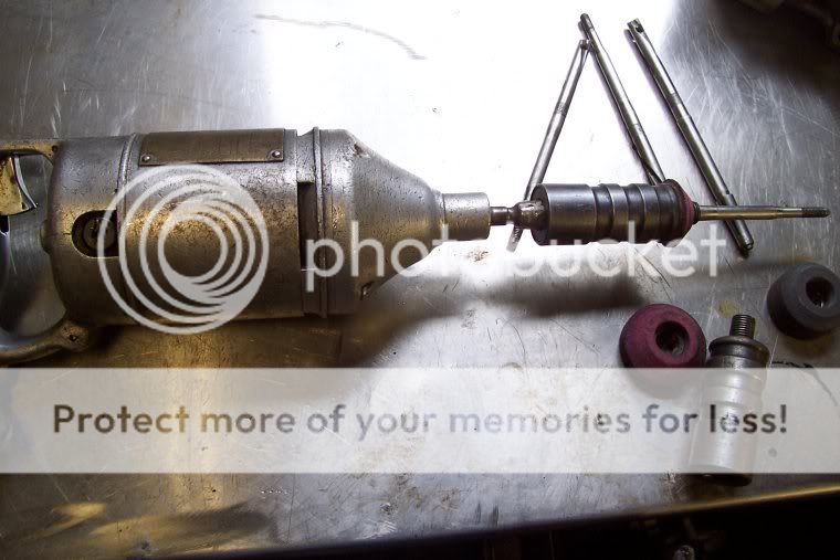 The grinder itself is just an old drill motor. 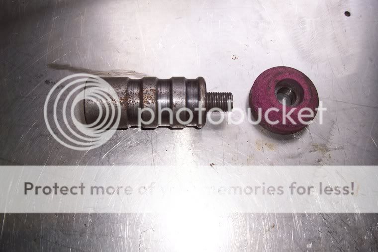 The arbors are pretty much what I expected them to be  The pilots were a bit of a suprise. They wedge themselves into the valve guides. Since this setup is so old it does not have any pilots that would fit a 7mm valve guide. So I cannot use this, but I can learn from it.  And the stone shaper is simpler yet better than I had imagined. I aqcuired a few items earlier when I decided to try this 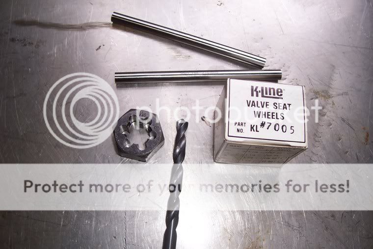 The Die is a very odd size. That makes them either very expensive or very cheap. I got lucky and found it cheap. 9/16"-16 to suit grinding stones made for old black and decker valve seat grinders. A 1.125 stone, a new 7mm drill bit and some 7mm drill rod.  Some scrap 1.125" aluminum rod sacrificed itself to the lathe to become my arbor Put it all together and I have this  Ready the junker cylinder head.  Eeewww! Yet another 850 head that was stored for decades uncovered outside with no carb. I did a bit of googling and found this picture of the three angles  Shaped the stone to 30 degrees and made a cut  Next was 45 degrees and some Dykem 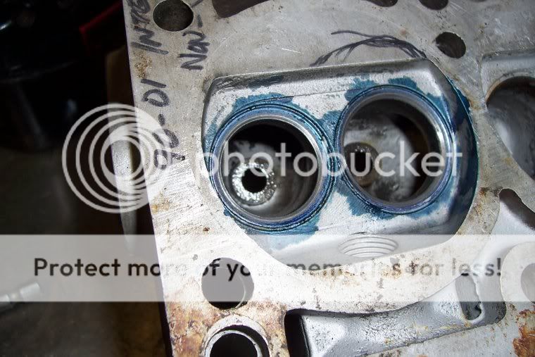 And finally 60 degrees and some more layout fluid to show where I am removing material  And finally all three angles after removing the dykem  I used a rough "general purpose" stone and I think for the good head I would step up to a finer finishing stone. I am going to take this head to some more knowledgeable people than I to get their opinions on the viability of my homebrewed valve job and hardware. I am pretty convinced that I can do this. Hell I already have, but I think I might need to learn a bit more about the angles and their locations/widths. OK OK I know that these days valve seats are cut with carbide and no longer ground to shape, but a neway carbide cutter itself costs several orders of magnitude more than my total engine rebuild. Yes I am sure that grinding is far inferior for many super awesome reasons but This has cost me about $25 so far and looks to be working just fine. Comments? I am interested to hear peoples opinions of this. |
| |
|
|
|
|
|
|
|
Well I just paid for an item that should significantly increase the horsepower potential of the new motor. Scored a vintage PBS 8 port cylinder head via ebay  Benefits to include. Zero charge robbing, one injector per cylinder, obviously better flow and it works with my existing exhaust manifold. Quite excited about this bit. I might go back to a hotter cam with the new setup. |
| |
|
|
|
|
|
|
|
BLOOD HELL! what a build thread, is there anything you cant do  What a awesome build. Good luck with it but looking at hwo its going you don't seem to need it  ! |
| |
|
|
Seth
South East
MorrisOxford TriumphMirald HillmanMinx BorgwardIsabellaCombi
Posts: 15,543
|
|
|
|
|
Your valve seat grinding method makes sense to me. The little I know about such things, its the 45 degree cut that actually meets with the valve to create the seal so the actual finish on the other two angles surely isn't so critical. And you could lap each valve into its 45deg seat in the old fashioned way with paste.
|
| |

Follow your dreams or you might as well be a vegetable. |
|
|
|
|
|
|
|
^What Seth said.
I understand that the 30 and 60 degree angles both help the gasflow and reduce the width of the 45 degree seat. The thinner the seat, the better the valve seals. However, the exhaust valve seat should be wider than the inlet valve seat - the wider area allows more heat to flow ffrom the valve into the head when it's closed.
It's well worth making sure that the diameter of the port behind the 60 degree section is as big as possible while still allowing a suitable width of 60 degree angle - that diamater is often very restrictive on stock engines, although it doesn't look too bad on your test head.
I did find a few suggestions on seat width on the internet a while ago - but I suspect that there are as many suggestions for width as there are engine builders/tuners...
And I've just read through the whole thread - it's a brilliant car, with a lot of very thoughful modifications. It's a credit to you, and I really like it.
|
| |
|
|
|
|
|
|
|
|
wow thats gonna be sweet
|
| |
If it ain't broke, I'll break it
|
|
|
|


 [*]
[*] [*]
[*]


 What a awesome build.
