madmog
Club Retro Rides Member
Posts: 1,160
Club RR Member Number: 46
|
|
May 21, 2024 16:52:57 GMT
|
I'm wiring the type of alternator as per the pictures and online have seen conflicting information. This is for a normal road car, not something simplified or adapted for racing. The conflict is whether the middle exciter wire is switched from the ignition switch with the ignition light per the top pic or whether it is connected to permanent live as per the bottom. The fact that it is a chunky spade terminal suggests the latter but if that were the case wouldn't that just be done internally? Also, some sources have mentioned fitting a diode to the ignition light to prevent current backfeed. Can anyone advise? Thanks 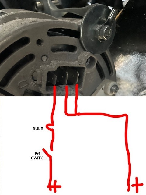 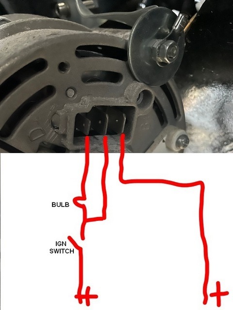 |
| |
Last Edit: May 21, 2024 17:00:26 GMT by madmog
|
|
|
|
|
|
|
May 21, 2024 17:25:11 GMT
|
|
I don't think the lower diagram is correct. If it's anything like my alternator (standard 17ACR), I believe the two large spade connectors are actually connected internally, and it's to allow a larger current to be carried along two reasonably thick cables instead of one massive one. My car only has a single thick cable connected.
I don't have a diode as far as I know - where would it go?
(I should add, I'm having trouble with mine at the moment in the charging area, so I'll be interested to see what other responses appear.)
|
| |
Last Edit: May 21, 2024 17:25:42 GMT by droopsnoot
|
|
|
|
|
May 21, 2024 17:30:19 GMT
|
|
The top diagram is correct, as previously said the two large terminals are actually one. Fit a diode if the engine remains running when switched off .
|
| |
|
|
|
|
|
May 21, 2024 18:39:28 GMT
|
|
The top one is correct. The 12v from the ign circuit through the bulb excites the windings which is earthed internally so that once it's spinning produces 12v back out, the bulb see's 12v both sides so it goes out, so you know it's charging. The two large spades are connected internally. There's an internal diode.
|
| |
|
|
madmog
Club Retro Rides Member
Posts: 1,160
Club RR Member Number: 46
|
|
May 21, 2024 19:34:22 GMT
|
|
Thanks all, really appreciate it
|
| |
|
|
|
|
|
May 21, 2024 20:57:46 GMT
|
|
If you have a very low draw on the ignition (ie its switched via a relay) the live feed from the alternator via the warning light can be enough to hold the relay closed and it won't switch off with the key, a diode between the ignition switch and warning light prevents this.
|
| |
|
|
|
|
|
|
|
|
MSD ignition can run on a tiny current and the engine will keep running when switched off. A diode is needed in that case as well.
I have the T-shirt.
|
| |
Proton Jumbuck-deceased :-(
2005 Kia Sorento the parts hauling heap
V8 Humber Hawk
1948 Standard12 pickup SOLD
1953 Pop build (wifey's BIVA build).
|
|
madmog
Club Retro Rides Member
Posts: 1,160
Club RR Member Number: 46
|
|
May 22, 2024 11:20:25 GMT
|
|
I have a diode or two lying around and am wiring this part from scratch so easy enough to add it now than scratch my head later.
It's an old car with a chunky ignition switch and no relays in the legacy ignition system. It'll run a Megajolt.
Not sure if that changes anything.
Thinking logically, Since the Alternator has permanent live and earth, is it leaking current when the ignition wire is DISconnected. Eg does the ignition wire activate a relay within the alternator to disconnect it from the battery?
|
| |
|
|
jimi
Club Retro Rides Member
Posts: 2,058 
|
|
May 22, 2024 14:05:34 GMT
|
|
No internal relay, not in any alternator I've seen. The only way the alt will cause a leak when the ignition is off is if there is an internal fault in the alternator, a faulty diode in the rectifier pack can cause that.
|
| |
Black is not a colour ! .... Its the absence of colour
|
|
|
|
|
May 22, 2024 21:28:37 GMT
|
|
The charge light on an alternator has battery voltage via the ign switch on one side and alternator output voltage on the other, if they differ the bulb glows.
On an original system when you turn the ignition switch off the load of the coil etc means the charge bulb sees a significant current and as the resistance increases with load as the fillament warms up the voltage on the switch side of the bulb drops to a low value so the engine stops.
If you have a relay or electronic control of the ignition the current is tiny hence when you turn the ign off the bulb has a low resistance as it's not heating up with the current and continues to pass 12v so the engine stays running.
If you still have the ignition loads directly through the switch you won't need a diode.
|
| |
|
|


