|
|
|
|
|
Enter project 1: a variable sine wave generator. This is a very simple thing to do with an op amp. You put a Wien bridge across an op amp to make an oscillator that creates a sine wave: 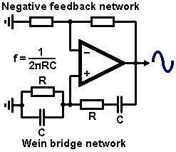 Pic from the Valve WizardObviously the first thing that popped into my head was surely you must have been able to do this with a valve, because you can make an inverting amplifier out of a triode by cathode-coupling it. And indeed you can. Bill Hewlett, founder of Hewlett Packard, patented this in the 1930s and it was built into the HP 200A. More here. Now, that got me thinking...  You've got pentodes these days. They've got multiple grid taps which can accommodate various types of feedback. Can you use one of those, which should make for a simpler circuit than a pair of triodes? The answer is yes, yes you can. The other advantage of pentodes is they are in modern, small, glass tubes whereas the triodes used in the HP 200A were the old-style metal tube with a top connection and octal base. Easy enough to find, but they are bigger, need octal bases and, more importantly I think I'd struggle to re-design the circuit to suit a modern dual triode because of the significantly higher gain. So here's a pentode oscillator I'm going to have a crack at: www.radiomuseum.org/forum/single_pentode_wien_bridge_oscillator.htmlI like the way it doesn't use a lamp to stabilise it - that's something I can visit later when I'm a bit more comfortable with the circuit and operation. Valve is a 6AS6, which I found NOS on eBay for not much. If I've understood it correctly, it's a pentode amplifier with a sharp cut-off and runs on a lower HT voltage (150V-180V). Only issue was when it arrived I wasn't expecting this: 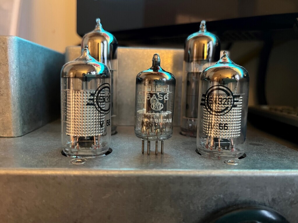 Next to the EF86 pentodes I normally use, it's tiny and only has 7 pins. It's a smaller form-factor and uses a B7G base. Never mind. Bases ordered. I think for this first attempt I'll need to follow a working circuit and tweak/modify as I go. But it does mean for future tinkering, it'll be difficult to switch it to an EF86 and it's not compatible with the B9A bases I normally use. The only other potentially difficult-to-find item for this was a big, variable dual capacitor. Luckily, it looks like Ham radio circuits use these and I managed to find an old one with 2x 500pF (EDIT: 525pF x 2 + 17pF x 2 with 1.5:1 reduction drive). That means it'll work with the above circuit and it should be compatible with the basic HP 200A circuit too. 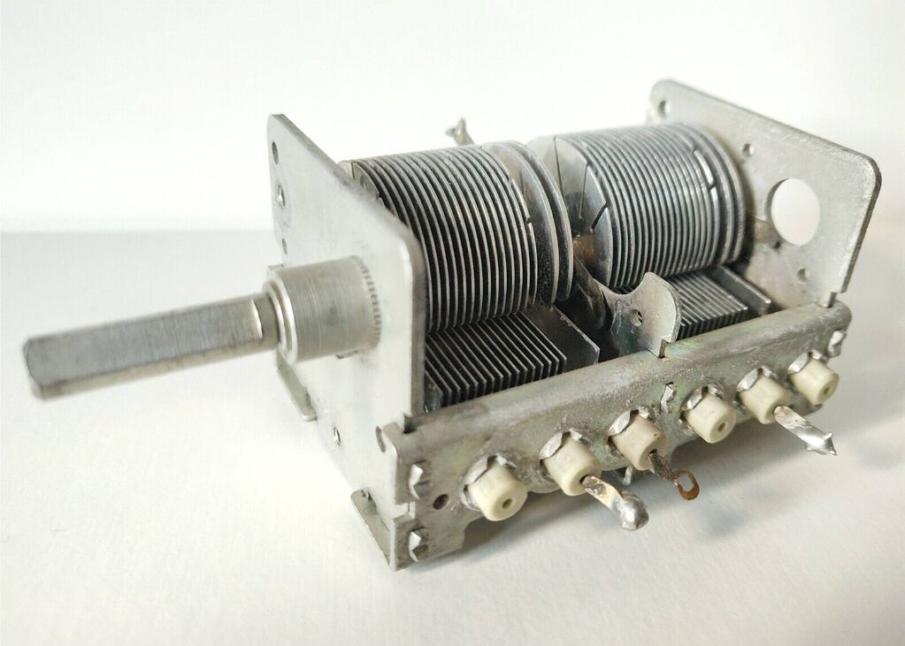 Size-wise, it's about 100mm long and about 50mm square. Fairly big but not too chonky. So that's the start: get a frequency generator running and then I can start chopping it up with various filters. _____________________________________________________ Afternote: The actual theory for these circuits is quite difficult to find on the internet, hence I'm struggling to translate it to suit the normal valves I use. I'm mostly finding the good info by accident. It's in old books out there but I wouldn't know where to start looking for those. In the meantime, I need to pick my way back to the beginning of this article in Wireless World from 1959, which features EF86 valves. I also need to have a think about how I'm going to mount this up. I was originally going to use diecast aluminium boxes like my amps. Perhaps some aluminium construction kit stuff as a mounting frame and sticking to standardised units would make more sense. Blank Eurorack panels look like a thing so maybe I'll commit to that sizing? I think Look Mum No Computer does this, just knocks up basic panels and puts them in a Eurorack frame. |
| |
Last Edit: Jun 7, 2023 15:00:44 GMT by Jonny69
|
|
|
|
|
|
awoo
Posted a lot
  
Posts: 1,507
|
|
|
|
|
Oh yeah, this looks sick! Looking forward to this.
Was going to mention LMNC but looks like you’re well aware.
I have one of those variable capacitors in my record lathe and was never quite sure what it was.
Have you delved in to the bbc archives? Don’t know if they necessarily have what you’re looking for but there is a lot of info on old audio equipment, a real goldmine if you want to go deep in to the inner workings of old technology.
|
| |
|
|
|
|
|
|
|
Oh yeah, this looks sick! Looking forward to this. Was going to mention LMNC but looks like you’re well aware. I have one of those variable capacitors in my record lathe and was never quite sure what it was. Have you delved in to the bbc archives? Don’t know if they necessarily have what you’re looking for but there is a lot of info on old audio equipment, a real goldmine if you want to go deep in to the inner workings of old technology. Cool! I've sort of looked into the BBC archives. The small valve amp I built in the other thread is the BBC version of the Mullard 3-3 and the circuit and explanation came from there. It's another site which is an absolute goldmine but difficult to navigate as it's basically an archive. I spent some time pulling out the Elements of Electronic Circuits articles from the Wireless World archives which cover quite a lot, if not all of the information I was looking for. The series progresses into timebases, analogue logic gates, counters and then differentiation and integration. Alongside that, I spotted articles with early valve-based computers being demonstrated. Pretty cool! Looks like all of the Elements of Electronic Circuits articles were published in a book in 1962 called Elements of Electronic Circuits Building by JM Peters. I think from those I might be able to work out some simple filters which would normally be done with op amps and logic gates. |
| |
Last Edit: Jan 4, 2023 11:30:24 GMT by Jonny69
|
|
|
|
|
|
|
AMAZING! I'm in for the ride  |
| |
|
|
|
|
|
|
|
I had a chance to go through the Wien Bridge article. It covers the theory in detail and then summarises by walking through the procedure: 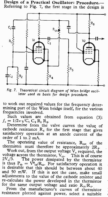 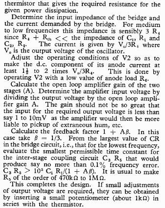 A couple of key bits here are using the curves in the valve datasheet to choose the components and specifying the thermistor. Those were two things where my knowledge ran out, particularly in the Hewlett circuit which used a bulb. The next thing I'm going to look at is to plumb in some component values and see if I can design something around a pair of EF86 valves. The only thing at the back of my mind about the little 6AS6 is the maximum anode voltage of 180V. Most of the valve transformers I come across have anode voltages in the region of 300V, so I'd have to shed 100V somewhere and that means dumping it out as heat through a resistor. In the meantime, I should probably bash together an Atari Punk Console or something to start making funny noises that I can stick filters on. Here's some kind of filtered APC from that site. Also LMNC put three APCs together to make some apcapcapc, uh, thing, that makes cool noises. |
| |
Last Edit: Jan 5, 2023 9:27:12 GMT by Jonny69
|
|
|
|
|
|
|
|
|
|
And then if I want to get really clever, I’ve got some ancient decade counters. If I’ve understood correctly how they work, each clock trigger gets it to count up from pin 1 to pin 10. Thus if I ran the clock off the output of the astable stage of the APC, pin 1 would get enabled every tenth click and should therefore be able to run a second monostable one octave lower. Is that right?
|
| |
|
|
|
|
|
|
|
Hi Jonny, not only am I a part time gigging keys player, composer, recording engineer and producer but I have always been seriously into electronic music, from the early stuff from the likes of Jean Jacques Perez in the 1960s, then Kraftwerk, JM Jarre, Vangelis etc, then 80s stuff from kids TV music (Levy Saban stuff for example but also stuff like Terrahawks theme) to testcard / library stuff then Italo / Space synth (had a big ZYX record collection) loved the 90s rave/jungle stuff. Love synthwave music. I have also always collected old gear. in the 80s it was TVs,  video recorders such as U-matic, and open reel tape machines, 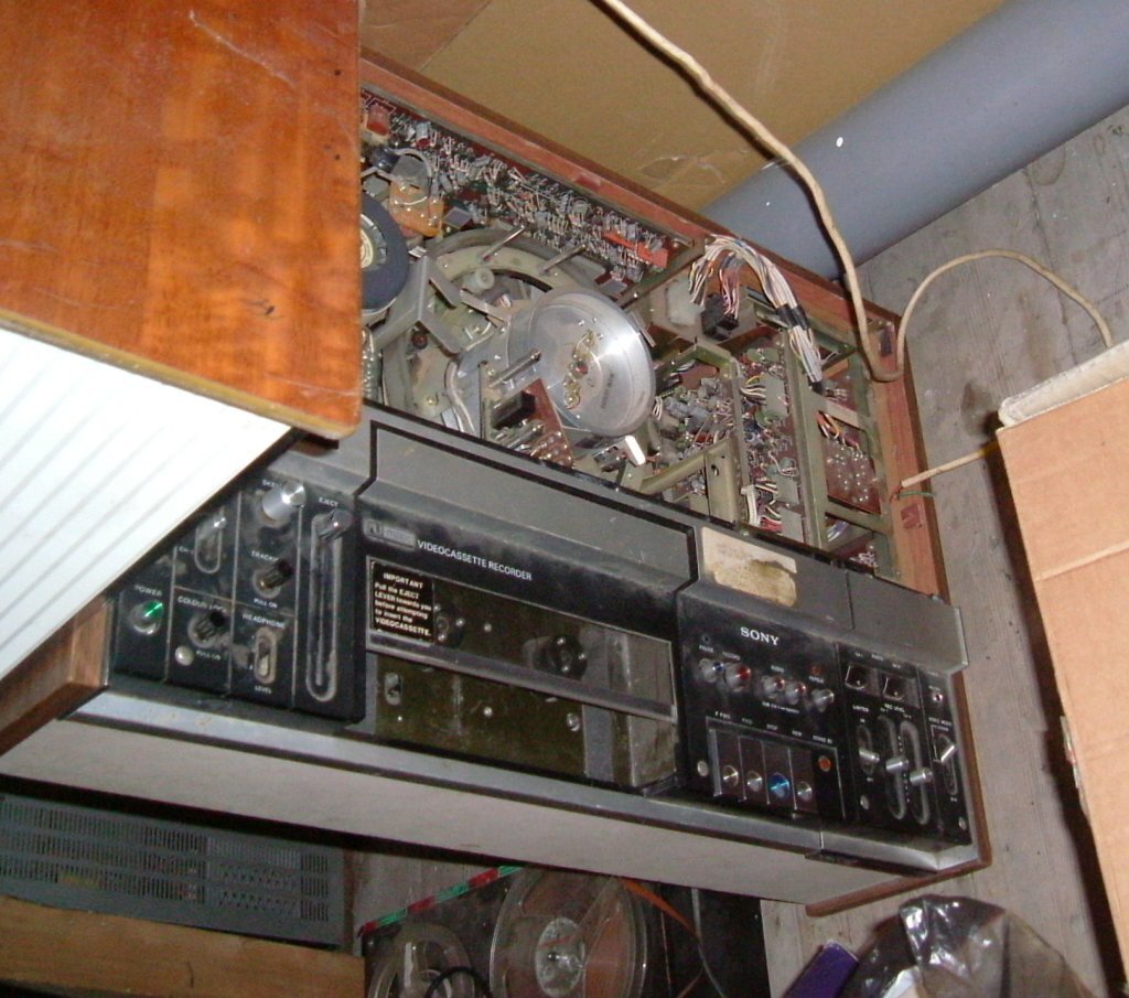 and as far as synths go I have a 1974 Korg mono synth.  I also have a 1970s Yamaha electric piano (sadly broken) and recently picked up a partially working 1970s Eminent organ. 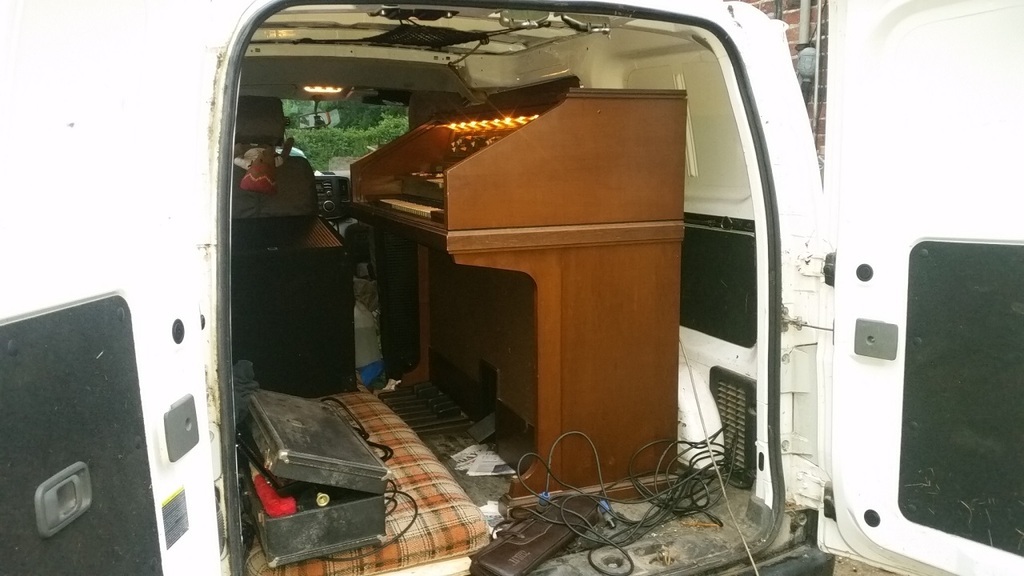 Sadly I'm not that great at fixing this stuff. I did revive a skip-find DX7 a couple of years back but can't quite figure out why my organ has no bass frequencies. Inside the Eminent.. 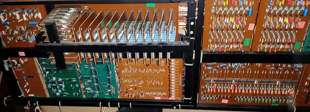 Inside the Yamaha CP30 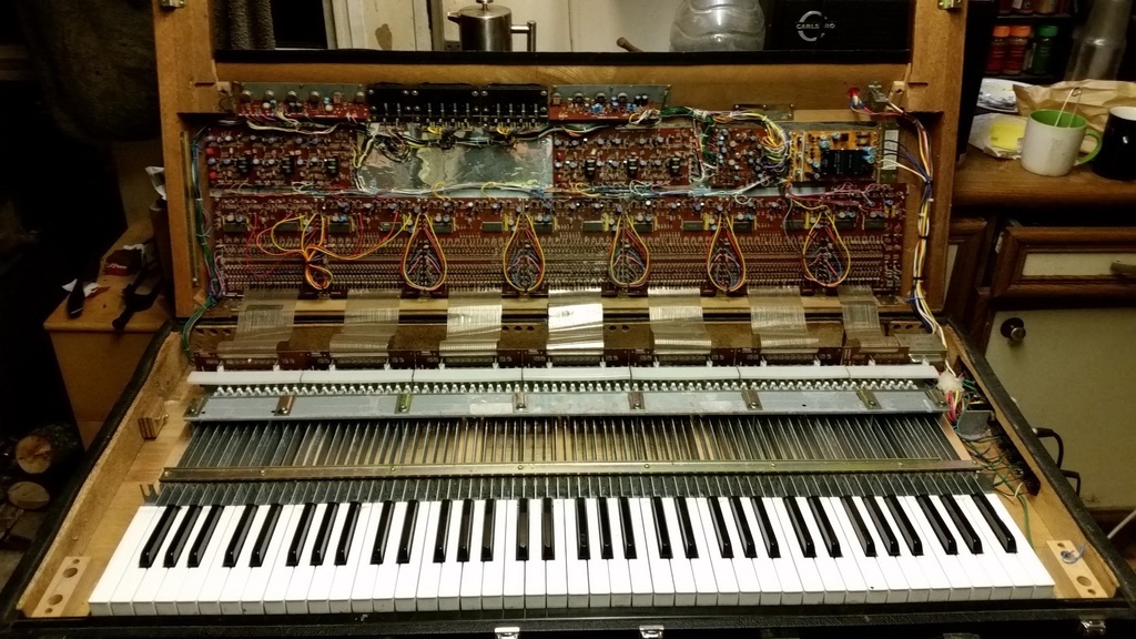 All the best with your electronic endeavours i often watch vids by the likes of lookmumnocomputer and fran blanche, I'm just better at mechanical things (and simple car electrics) than electronics. |
| |
Last Edit: Jan 6, 2023 20:10:05 GMT by datman
75 Range Rover 2 door 82 Range Rover 4 door
84 Range Rover 4 door 78 Datsun 120Y 2 door
78 Datsun 620 Pickup 81 Datsun Urvan E23 86 Datsun Vanette van
98 Electric Citroen Berlingo 00 Electric Peugeot Partner 02 Electric Citroen Berlingo
04 Berlingo Multispace petrol 07 Land Rover 130 15 Nissan E-NV200 15 Fiat Ducato
|
|
|
|
|
|
|
Sadly I'm not that great at fixing this stuff. I did revive a skip-find DX7 a couple of years back but can't quite figure out why my organ has no bass frequencies. Inside the Eminent..  Inside the Yamaha CP30  All the best with your electronic endeavours i often watch vids by the likes of lookmumnocomputer and fran blanche, I'm just better at mechanical things (and simple car electrics) than electronics. That’s some cool stuff, check out all those circuit boards! So I always assumed the dat in your username was short for Datsun. Given what you do, is it actually DAT? I reckon the organ and keyboard wouldn’t be all that hard to fix. It looks pretty daunting but it’s basically lots and lots of the same thing plugged into itself, which makes tracing the wires and finding which bit isn’t working quite easy. You could probably do most of it with a multimeter to find the bit where the electricity stops. Did you see Sweatpea’s thread a while back? forum.retro-rides.org/thread/162499/heard-duran-fixing-analogue-synth I’d forgotten about Fran Blanche. She’s a bit handy when it comes to obscure electronics. I was trying to find some information about some bizarre CRT number display tubes and she’d not only managed to find one but set it up on a 2kV supply and worked out the drive electronics! |
| |
|
|
|
|
|
|
|
Jan 13, 2023 10:24:25 GMT
|
Some handy bits and bobs in the post. IC holders and some old multi-position rotary switches: 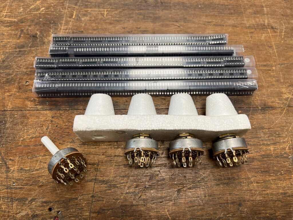 The switches are the same as modern plastic ones in that you move the peg round to another hole to set the number of positions: 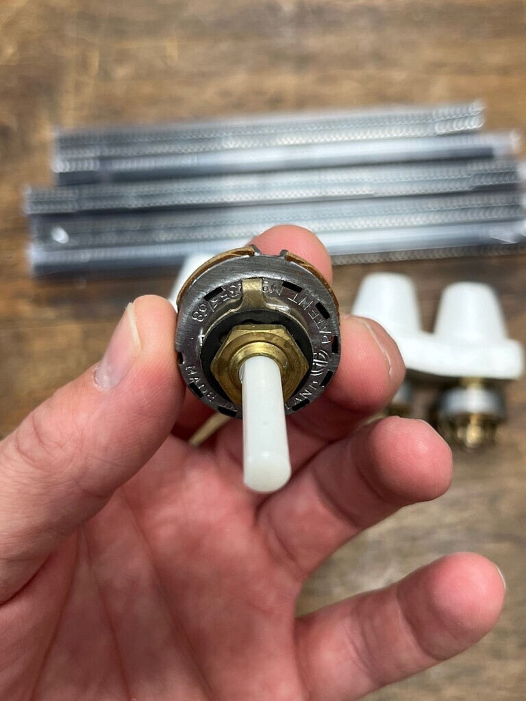 |
| |
|
|
|
|
|
Jan 17, 2023 12:15:52 GMT
|
Bit of a slow start going on here. I thought I'd have a look at starting an Atari Punk Console (APC) at lunchtime so had a look in my stash to see what I've got. I was actually looking to see what potentiometers and Veroboard I had left, but I found these that I'd forgotten about: 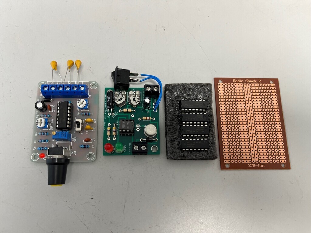 Left to right: eBay function generator module, eBay 555 astable module, some 556 chips, Radio Shaek prototyping board (shameless copy of a Radio Shack one). The Radio Shaek board was what I was going to put the APC on, but then I stumbled across the 555 astable module. I can't remember exactly why I bought this but I think I had an idea to make it into a modular driver for my pulsejet spark generator. It has a small amplifier on the output so it's quite happy driving a load like a speaker. It has variable duty cycle so basically does what the APC does but twiddling with screwdrivers instead of knobs. It was fun for about 5 minutes and that was that. The 556 chips were a bonus find. They're two 555s on one chip. I think I got these for a little device I made to interrupt the engine auto-stop function on my car and make it operate more aggressively. Forgot about them. Now, the function generator - this is a little more interesting: 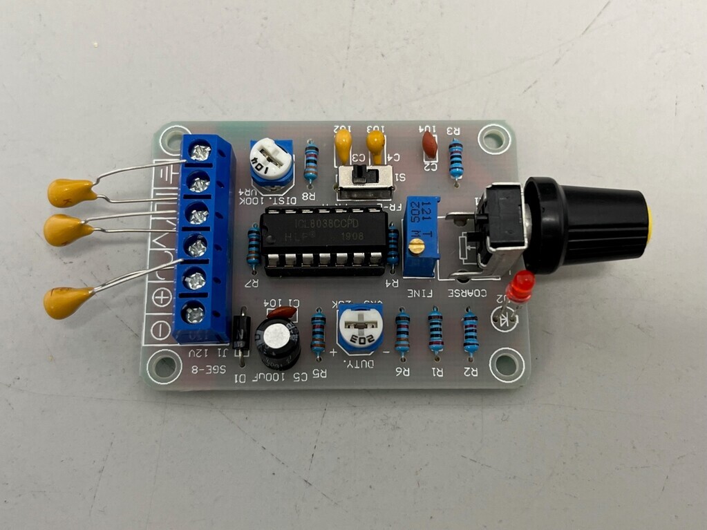 I do remember this now, but forgot it was in there or what it did. I got it when I was looking to revive my battery-powered valve amp project, when I wanted something quick that put out a sine wave, but I couldn't be bothered with setting up a Wien bridge with an op amp etc etc. This puts out a sine wave, triangle and square. Frequency is controlled by a potentiometer on the board and it has a decade switch. Looking on the scope, the two preset pots are for duty cycle and voltage +/- trim (moves the waveform up or down). The only thing which is odd about the board is it has no coupling capacitors on the outputs, so the output is offset by the DC supply unless you put them inline like I have. Looking at the datasheet though, perhaps it's supposed to be run on +/-12V - I haven't checked if GND and the - are coupled. The ICL8038CCPD chip which drives it is a voltage controlled oscillator (VCO). This is interesting for a synth project because that's how synths work. In fact, they generally comply to a standard which is 1V per octave. I need to read up a bit more on this, but I'm pretty sure I can make this thing play notes if I set something up with 1V per octave. They're also pretty cheap on eBay so it doesn't matter if I blow it up. |
| |
|
|
|
|
|
Jan 20, 2023 10:13:02 GMT
|
Another update with nothing really to show for it, just theory. I was looking at ICL8038 circuits and found an old HTML site: yusynth.net/index_en.phpIn the links page (remember them?) there are links to loads of other HTML pages which, amazingly, many seem to still be online. One of them is René Schmitz's page which has some valve circuits: www.schmitzbits.de/vtvcf.htmlOne circuit that caught my eye is a voltage controlled filter (VCF): 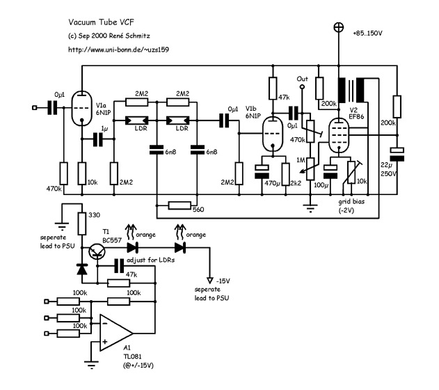 I've had to do some deciphering because I don't fully understand the electronics and it's not completely explained. It looks something like this. Top half of the circuit diagram, the signal input goes into the 0.1uF capacitor. Signal output is buried in the top right hand side of the circuit diagram. The voltage control for the filter comes from the LDRs and it's driven by the circuit at the bottom. Various control voltages go into those 100k resistors and are summed up by the op amp. That circuit drives the LEDs. The LEDs are basically taped directly to the LDRs, so the light varies the resistance in the LDRs and therefore controls the frequency of the filter. That probably means I could initially knock something up with twiddly knobs instead of LDRs. I've got some 6N2P valves on their way (almost the same as an ECC83) so I'm interested in giving this one a go. I'm not sure about the LDR route though (more light = lower resistance) because I just think it might be opening a can of worms with regards to choosing the actual values for LDR and brightness of the LED. I'd like to look into digital potentiometers as an alternative. Unless I used filament bulbs maybe? |
| |
Last Edit: Jan 20, 2023 11:33:43 GMT by Jonny69
|
|
|
|
|
Jan 24, 2023 10:42:21 GMT
|
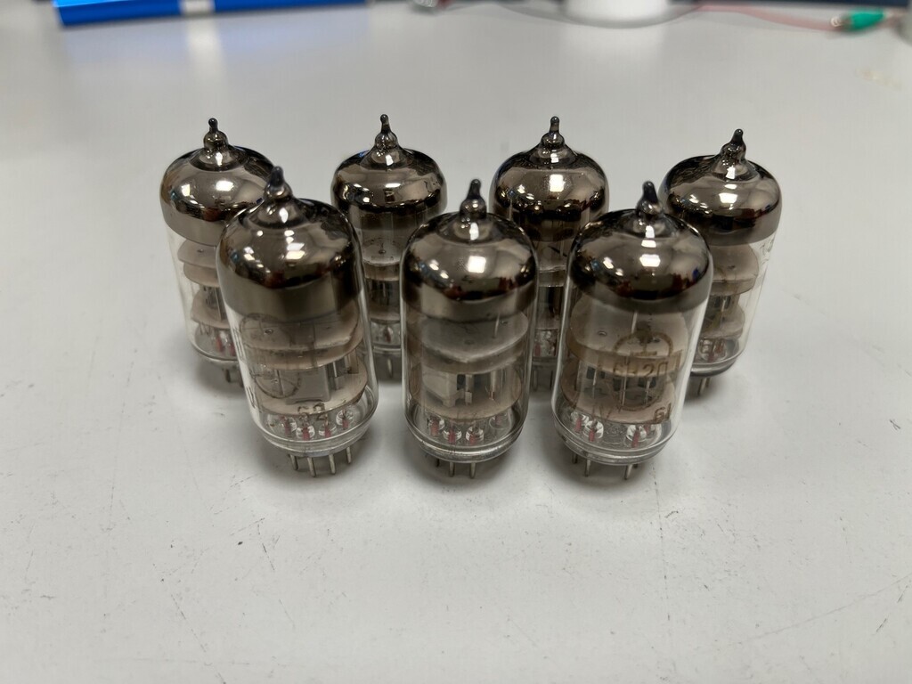 My 6N2Ps have arrived from Ukraine. As I mentioned before, these are almost identical to an ECC83/12AX7 dual triode. The main difference is the heater layout is slightly different in the 6N2P: 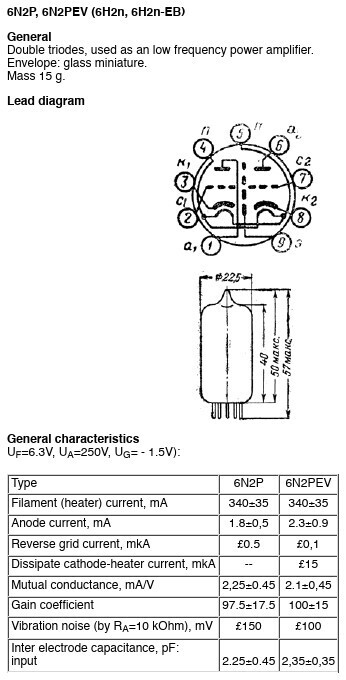 It's not a direct swap with an ECC83 but it's only a minor change. The key thing for me is I need to use a couple of them. ECC83s and 12AX7s are popular in the guitar world so they're expensive, whereas these can be dead cheap. In the Hi Fi world, it's a good thing to have matched pairs of valves and so there are lots of eBay listings for pairs of 6N1Ps which have had their parameters measured and matched up. You pay a premium for these ones. I'm not too bothered about that because I mostly need singles, so I can hoover up the lists of unmatched pairs and singles. I went for a batch of seven and kept my fingers crossed that they were mostly similar. That said, it is nice to at least have a pair from the same batch, so if I were to put them in a stereo amplifier or something I'd have two that I knew were similar (and look the same). I did actually get two pairs with same dates which is a bonus. Nice early pairs too, which always feel like they're better: 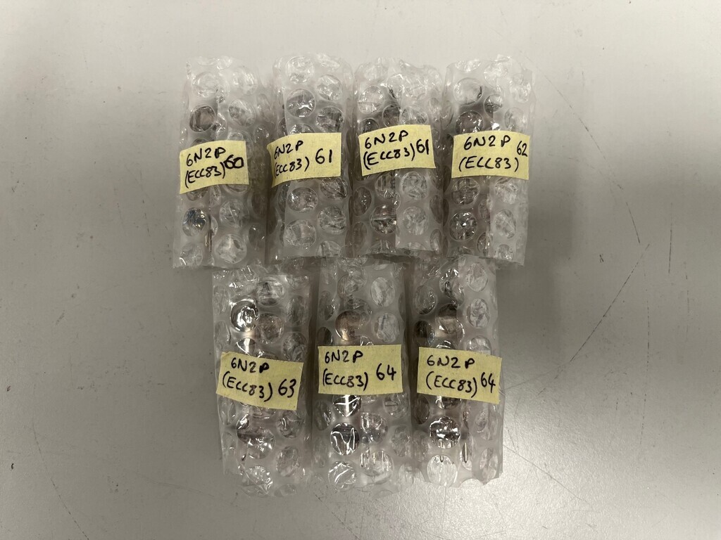 So. One of the odd ones is going in the Magic Eve VU meter so I can put the ECC83 I used back with my Maplin Millennium amplifier. It'll need a minor modification to the heater wiring to do this. Another will probably go in the VCF circuit above ^. Another will go in a LMNC Safety Valve. And that leaves two pairs for something else, which has worked out quite well. On the subject of LMNC, I decided I was starting to go round in circles with the oscillator. To get the project started I have decided to buy an oscillator kit so at least I'll have something to start with that a) runs on the right voltage, b) puts out the right voltages, c) puts out the right fequencies, d) is controlled by the right voltages and e) has the right degree of control with the pots and input voltages. That was looking like a lot of things to try to get right on a first attempt, so I have gone for a LMNC VCO PCB and front panel. While I was there I splashed out on a Safety Valve PCB and panel and a reverb PCB and panel. That now sets my module size as 10cm x 20cm and means I'll be using full size 1/4" jack plugs instead of the smaller 3.5mm ones on Eurorack. Anything Eurorack will be compatible because it runs on the same voltages and it's just smaller, so it will fit in the rack with an adapter. |
| |
|
|
|
|
|
Jan 26, 2023 11:55:22 GMT
|
A small but welcome addition to the test kit fleet - an analogue function generator that I pulled out the e-waste skip at work. If you're not familiar with these, they generate sine, square and triangle waveforms at any frequency you want. It's a bit bashed up but I've been looking for one for ages. I've got a digital one (the white box I used in this post), but these old twiddly-knob analogue ones are SO much easier to use. First job was to check it over: 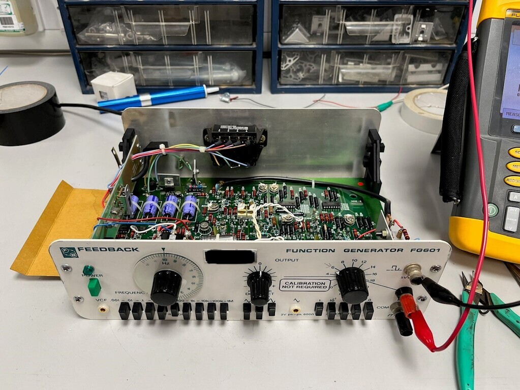 It looked dead at first, but all the power was there and it just seemed to be a dead power indicator (green lamp on the front). I know how to do power indicators. I've got a bag full of Soviet indicator lamps doing nothing, so another one of these was in order: 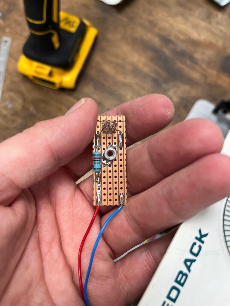 That goes on the back like so. Not quite as straight as I'd like it but mehhhh: 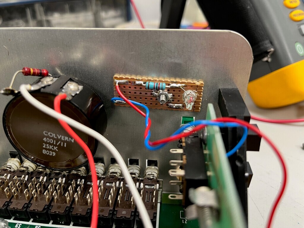 Voltage across it is 120V as it's centre-tapped in the transformer so it can do US voltage as well. From my previous escapades with these, I know 100k on 240V was a bit too bright, so that meant 50k on 120V would also be too bright. I went for 82k and it is spot on: 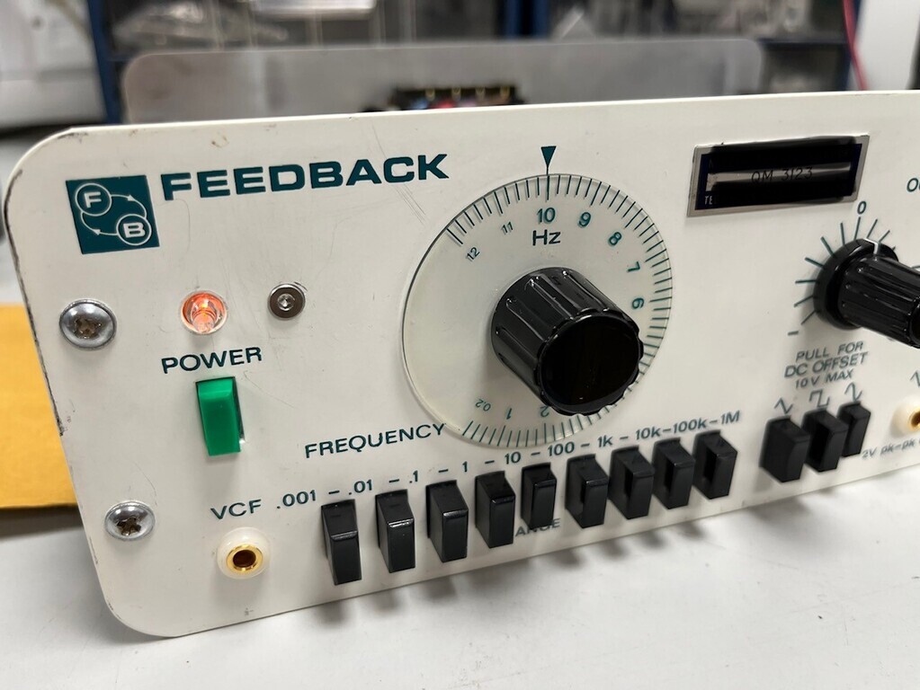 And here it is. It needs a few cracks on the case dealing with and someone had thieved the feet for some reason, but it's basically all there and working. 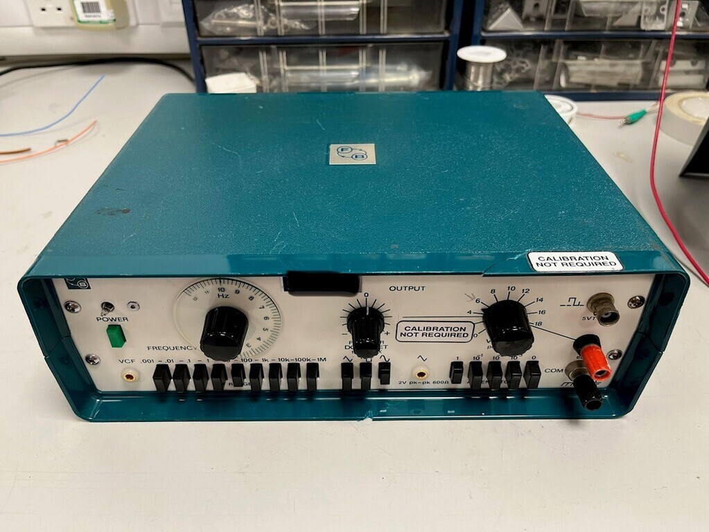 |
| |
|
|
|
|
|
Jan 27, 2023 17:00:28 GMT
|
The other e-waste skip finds are a pair of old CRT scopes: 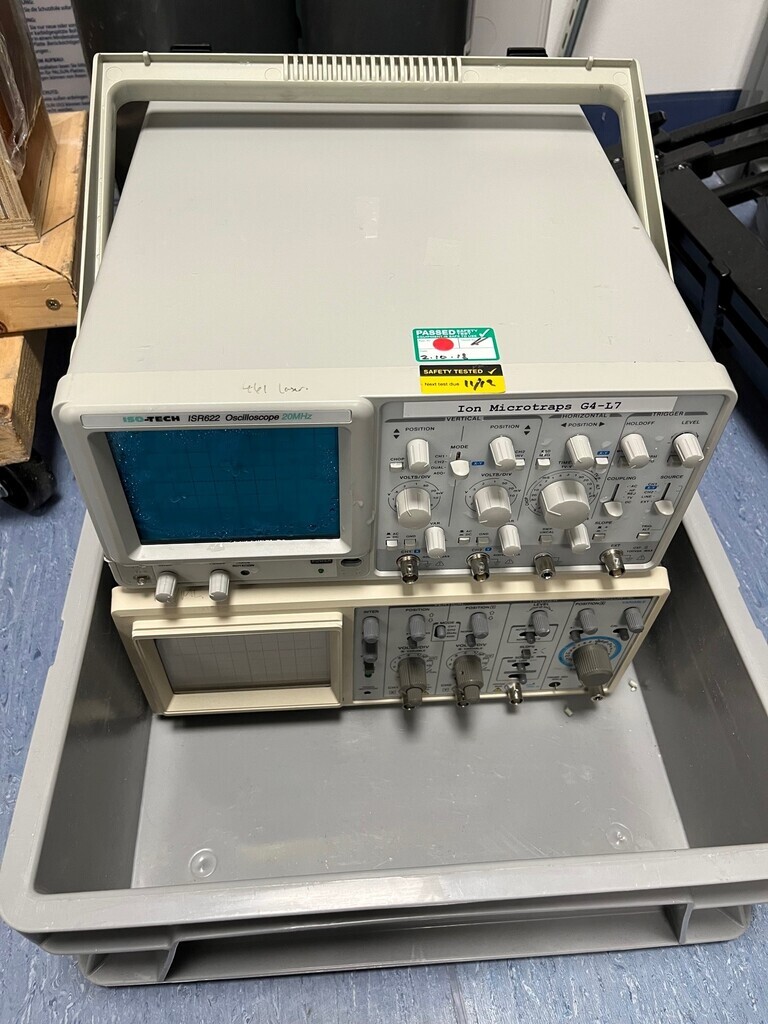 Again, I used to prefer this style to more modern digital scopes. My initial preference was for the older, browner one but I grabbed both just in case. The brown Goldstar. Both scopes had been out in the rain so I started by giving it a visual inspection internally and it was completely dry inside. Then checked the earth continuity, plugged it in and checked the supply voltages were getting round it, then popped it back together and connected it up to a signal. It's a bit dim but for some reason the trace almost doesn't show up at all in the pic: 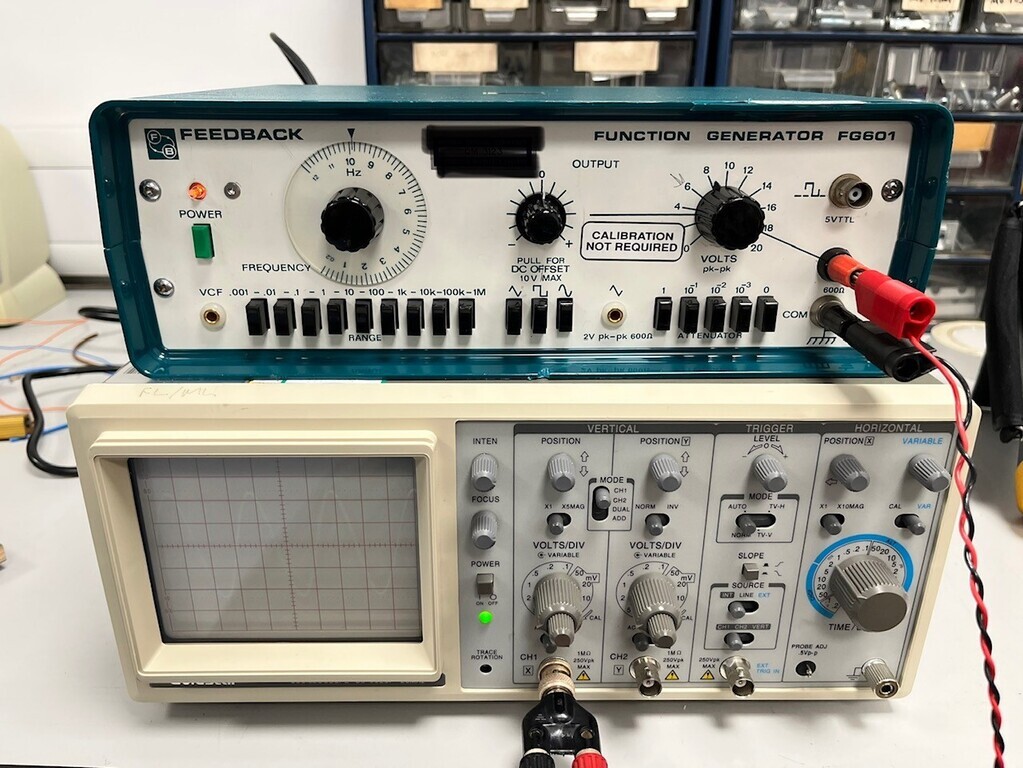 So that one works fine and amazingly I found a copy of the manual: www.allaboutcircuits.com/test-measurement/oscilloscopes/os-os-9020p/service-guide/The other one had definitely got a bit more wet: 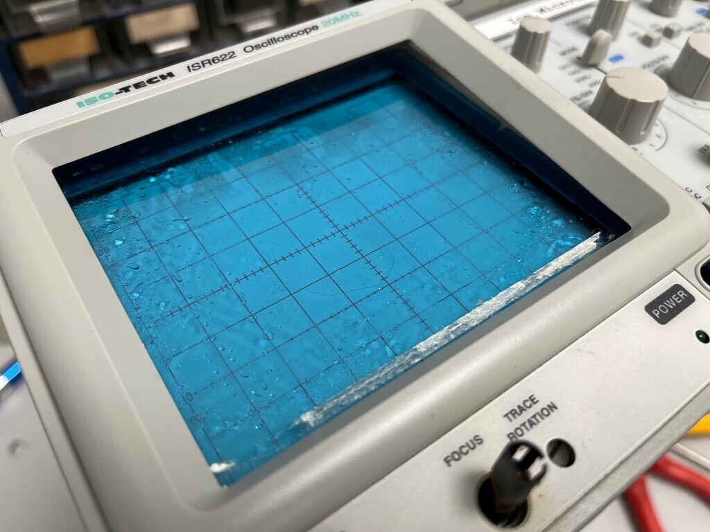 Looking inside, it was only wet behind the plastic screen cover, so I popped that off and dried behind it: 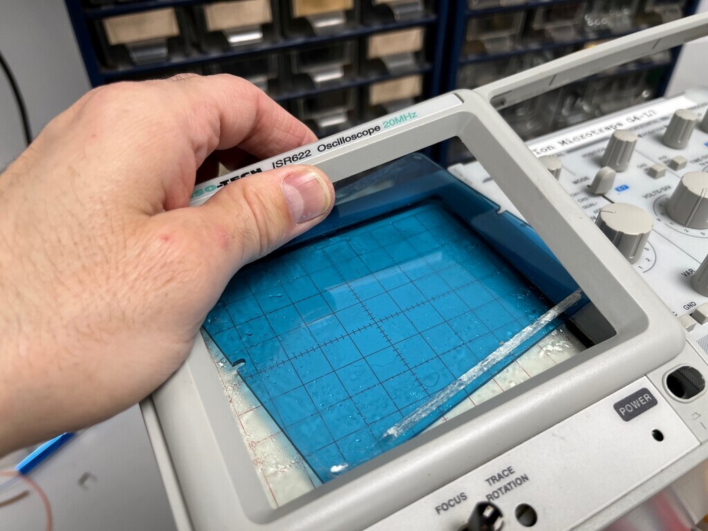 Unfortunately, this one does seem to be DOA. It switches on, but I can't get it to light the CRT: 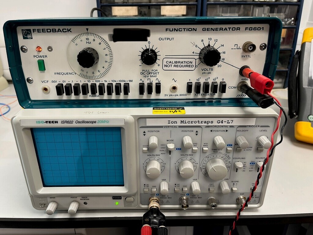 I wonder if it got too much of a bash when it went in the skip. I had a closer look at lunchtime but couldn't spot anything obvious (I'm no CRT expert so I'm proceeding cautiously). Supply and control voltages seem to be there. There's an internal fuse which seems to be ok. Couldn't check the HT because I don't have anything that can measure that high voltage (probably around 2kV). A few bits look like they've been running hot but nothing looks burned out. Wasn't sure if I was supposed to be able to see the heater in the CRT glowing but I'm not 100% confident I really know what I'm looking at at this point. Can tell you that it's a bit scary working next to a live CRT! Caps are rated at 6kV. I think this one might actually be chuck-it-back-in-the-bin dead. The Goldstar scope has a full set of circuit diagrams and troubleshooting guide, whereas the ISO-Tech one doesn't, but I wonder if I can translate anything across with regards to testing the tube. Next week I'm going to go through the setting up and calibration procedure in the Goldstar manual. It looks like you can set the intensity and focus at various points on the screen and it'll also teach me a bit about how to set and interpret the scales. |
| |
Last Edit: Jan 27, 2023 17:04:33 GMT by Jonny69
|
|
jimi
Club Retro Rides Member
Posts: 2,223  Member is Online
|
|
|
|
 Who chucks working test gear like that (and the signal generator) in the skip ? there's always someone happy to get test gear like that for free. Good man for rescuing it 👍 I still have a working Avo in my garage, which was the first type of test meter (that and a wind up megger) that I learned on as an apprentice in the days before digital test gear 🤣 I used a similar FG on my last rig, we also had an old LG crt scope (very similar looking to your pictures) and a couple of digital ones, a Tektronix and a Fluke IIRC, the "calibration not required" stickers are very familiar  I can see the sine wave on your picture of the working scope, bit faint but it's visible 👍
|
| |
Last Edit: Jan 28, 2023 2:00:34 GMT by jimi
Black is not a colour ! .... Its the absence of colour
|
|
|
|
|
Jan 30, 2023 17:02:14 GMT
|
 Who chucks working test gear like that (and the signal generator) in the skip ? there's always someone happy to get test gear like that for free. Good man for rescuing it 👍 Sadly, I think they become liable if they sell stuff like this on or give it away. It's just easier to send it all off as condemned E-waste at end of life. I sort of wish a few more people would put it up on the intranet as freecycle though, quite a few of us can use kit like this and it's not easy to buy it new on project budgets. At lunchtime I set the brown scope up from scratch as per in the manual. Internally, you can set the CRT intensity, focus at various points, the horizontal and vertical centring and calibrate the time bases. The only one I couldn't do was the high frequency calibration because I didn't have a screwdriver small enough to turn the variable capacitor. Then I thought it might be fun to measure the frequency response of the small valve amp (I brought it into work). I set the signal generator at 1khz and adjusted the input voltage until I got 2V RMS at the output. This was an output point where there wasn't much distortion evident, so I should get a reliable RMS voltage reading. Then I measured the RMS output voltages at decades from 10hz up to 100khz. The FG put out a completely flat 1.5V RMS between 0 and 100khz which I was happy with. I then plotted the results on log scales and got this: 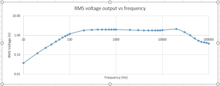 If I've understood how dB works, the -3dB point is where the output is halved, which should be the 1V RMS line. -3dB points therefore at 90hz and 40khz. It's a flatter response than I was expecting (I actually don't know what I was expecting). I knew it rolled off quite quickly below 100hz because you can hear it, and that's because of the small output transformers. I thought it sounded a bit muted at higher frequencies so I was expecting to see it roll off above 10khz but that doesn't appear to be the case. It might actually be a not very ideal interaction between the output transformers and my piezo tweeters. |
| |
|
|
|
|
|
|
|
Back to the dead scope. We'll call it scope 2.  I found a copy of the manual and went through the setup procedure but still no joy. I noticed both the scopes had the same make and model CRT tube in them despite them being about 10 years apart. They look different because the newer one has a blue filter on it - that's the only difference. There was a third, slightly smashed scope out in the bin and that got me bin diving again thinking: tube transplant? Up in the lab, scope 3 did indeed have the same tube in it. 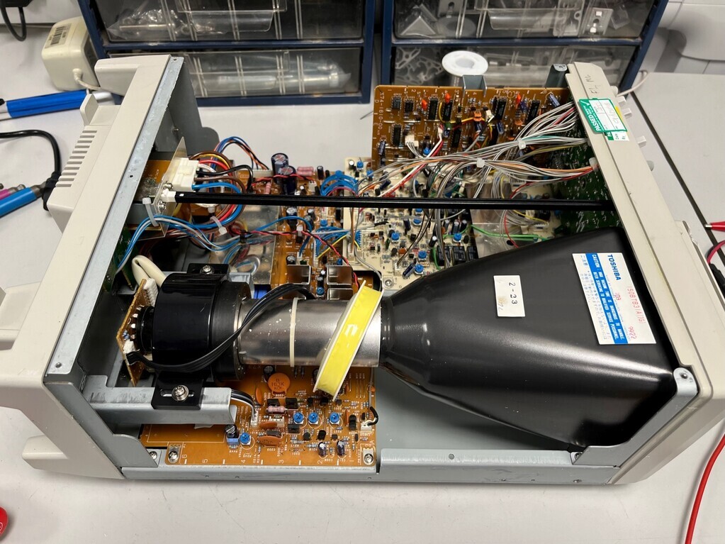 The tube worked but it didn't seem to be able to focus. I figured that wouldn't be a massive issue because it would at least let me know if the problem in scope 2 was a dead CRT or dead drive electronics. I checked everything for presence of high voltage and... 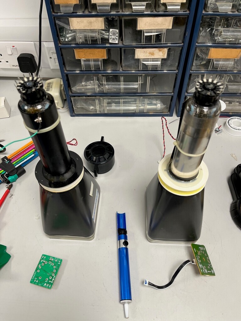 Taking those out wasn't REALLY REALLY SCARY at all, oh no. The tubes themselves are identical. The differences are that they have slightly different shielding in each scope and the connectors on the boards soldered on the ends are different. So I popped those off and swapped them between the tubes. I'm not sure what the coil halfway up the tube does but it's not high voltage. It was loose on the tube from scope 3 so I epoxied it back in place at the same time. Once tube 3 was fitted to scope 2, I got this: 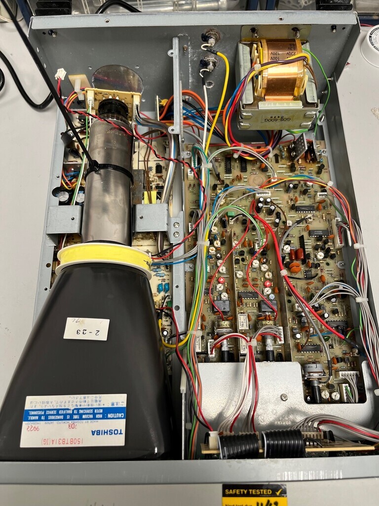 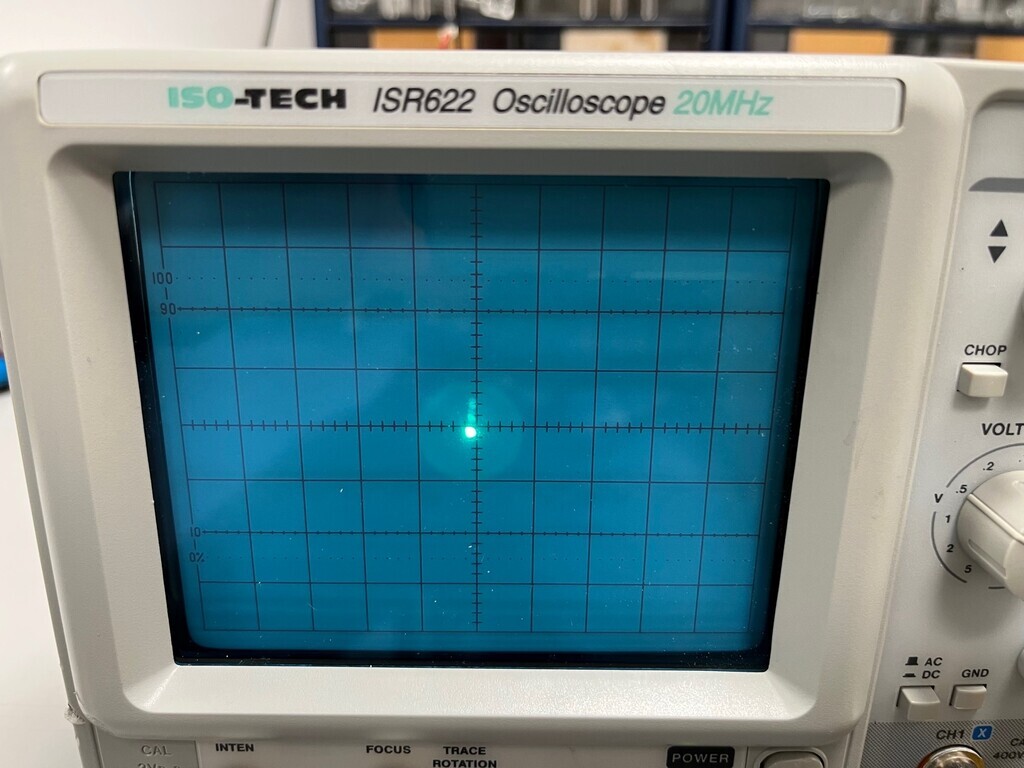 It lives! Well, kind of. It lives more than it did before. It traces an ellipse if you put a sine wave into it: 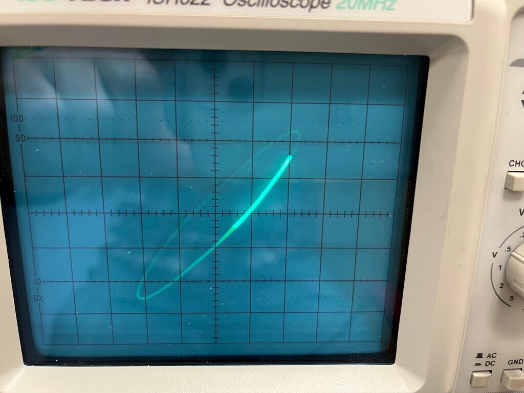 So something isn't tracking properly at the moment. The fact that it actually makes a trace, I can adjust the intensity and focus, and I can centre it vertically and horizontally suggests it's not that broken. I'm in too deep now and since I didn't die changing the tube I feel like I'm on a mission to figure it out and save this thing. Wish me luck. |
| |
Last Edit: Feb 3, 2023 10:48:02 GMT by Jonny69
|
|
|
|
|
|
|
One last thing. When I had Covid before Christmas I decided I was going to do a rebuild on the small valve amp. I quite like it and I'm sure some good quality output transformers will improve the low-end response. I bought some from Primary Windings and they finally turned up yesterday. 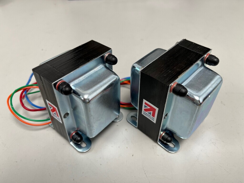 Ideally I'd like to keep the existing amp as it is because I like how small and neat it is, and I'd do a fresh build. Don't know how realistic that would be on my wallet. I brought the transformers into work to see if I could adapt them onto the existing chassis to temporarily try them out. Looks like they will go on. Also plonked the big mains transformer on to see what sort of size chassis I'd need to get all the big stuff on. It probably would all go on this size chassis with a bit of re-shuffling. 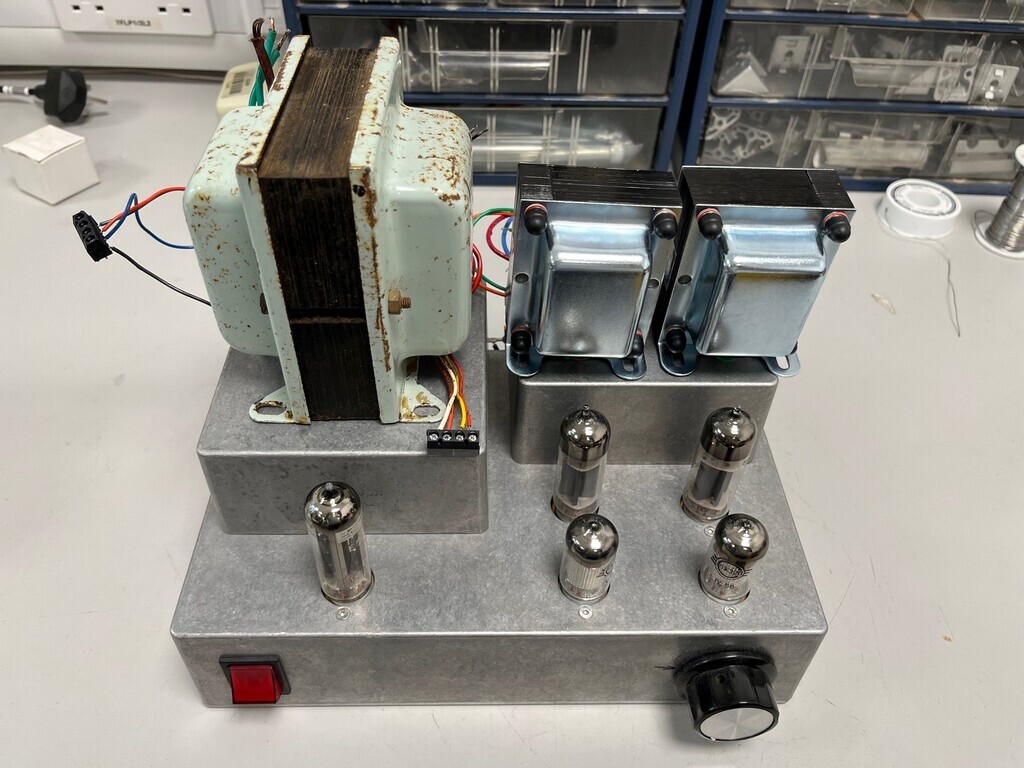 |
| |
|
|
|
|




 Who chucks working test gear like that (and the signal generator) in the skip ? there's always someone happy to get test gear like that for free. Good man for rescuing it 👍


