gazzam
Part of things
 
Posts: 741 
|
|
Jul 23, 2021 12:15:31 GMT
|
A small break from Jag work, but definitely related. I found out about a new tool that I didn’t know I needed. Saw a YouTube vid by Make it Kustom about a portable planishing hammer and I thought that would be a handy thing to have. Sort of like this one I found on Google images. 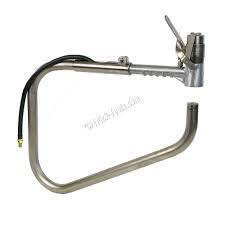 I bought a cheap air hammer and then realised I already had a more suitable one. My old one has an air control and that will make it better for this job. First up was to make a sleeve to hold the hammer. Which I didn’t take a picture of… it’s just a piece of exhaust tube with two small pieces of 1/4 id tube welded to it and then cut to let it expand just enough to let the hammer body fit nicely. Two 6mm bolts will clamp it securely. If the tool works ok I might cut the pistol grip off the hammer and redo the clamp. Will have to do something with the air control then, The sleeve was welded to some inch and 5/8 exhaust tube, simply because I had some on hand. 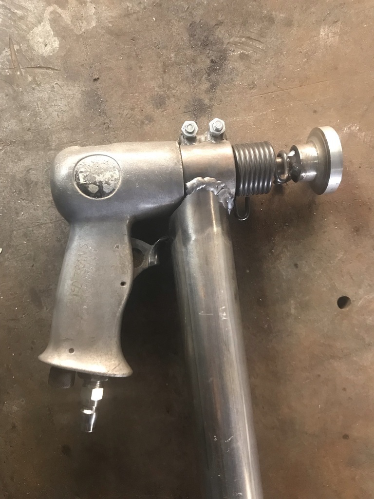 Cut the end off one of the old chisels and turned up a new head to weld on to it. Also lathed up an anvil and bored out an old bit of shaft to serve as an anvil holder. 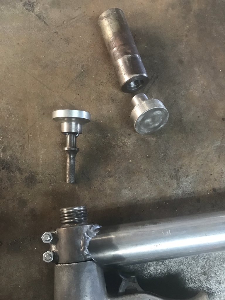 Made one side of the hinge by cutting a piece of RHS into the exhaust tube. 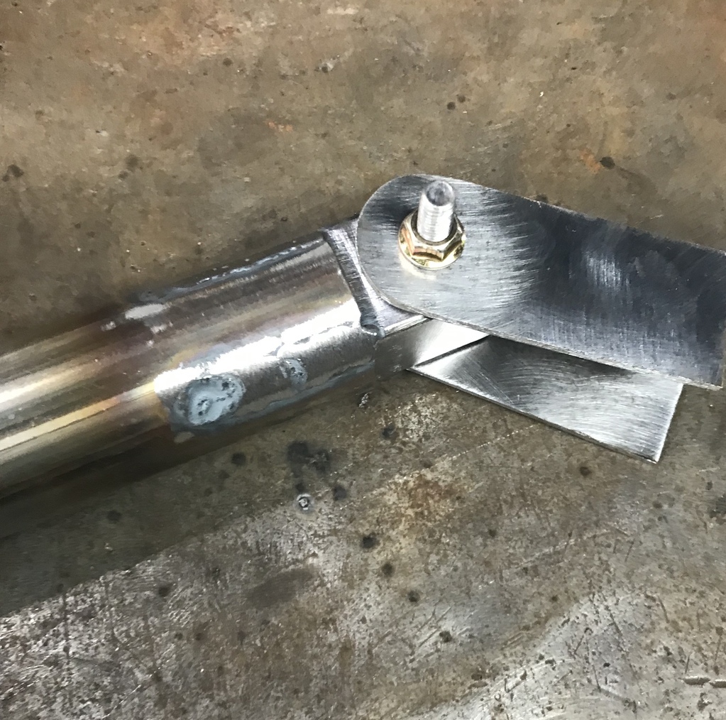 Then fit a 30 degree bend to the other side of the hinge. 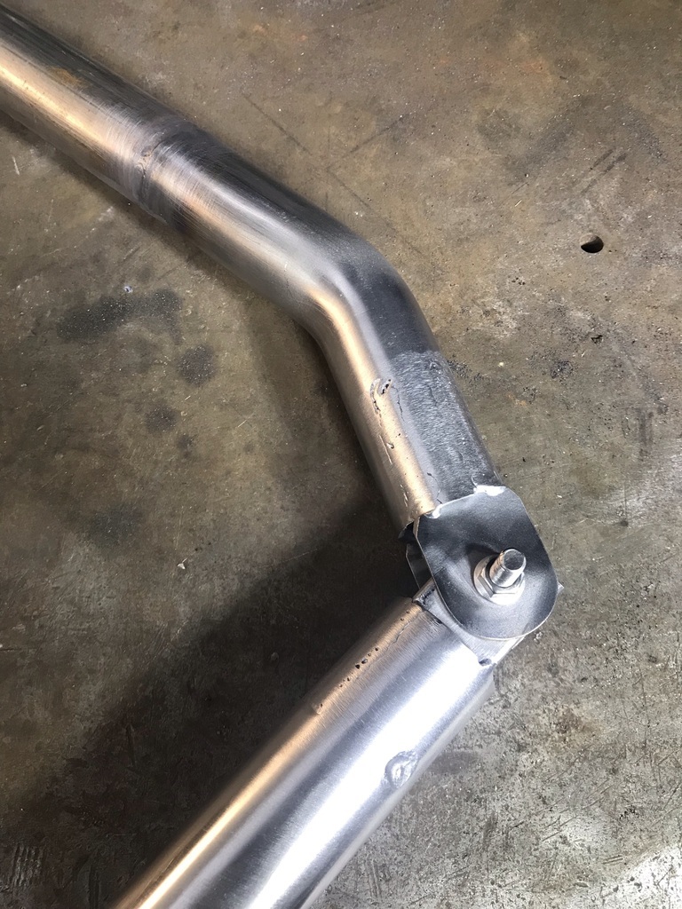 Tacked a pair of 90 degree bends to some short lengths to make the lower half that holds the anvil. 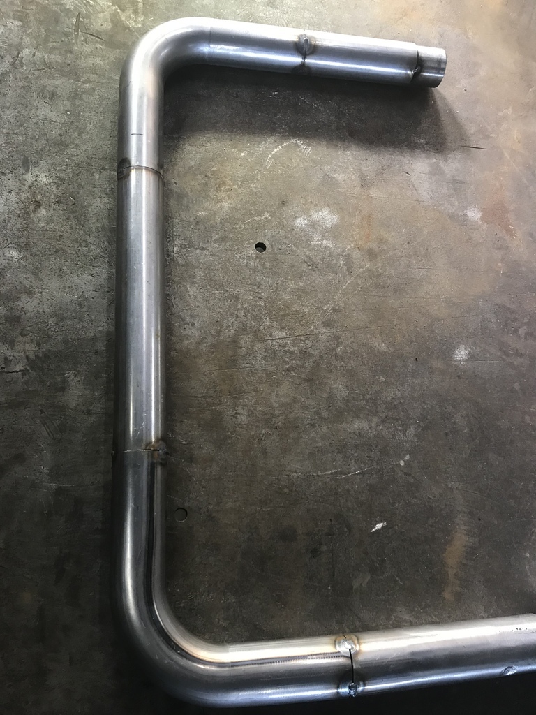 Difficult to get it all square and flat, but ultimately all that matters is that the hammer and anvil meet properly. Bit of adjustment needed at this point. But getting close. 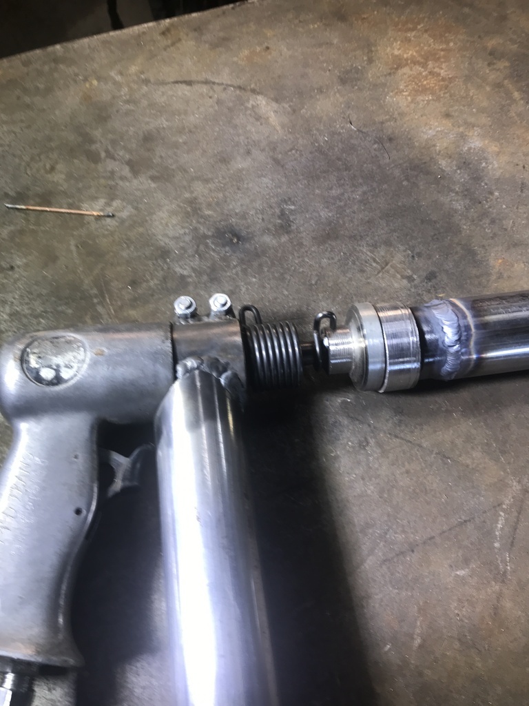 Once I was happy with hammer v anvil, weld up the entire frame, checking frequently for movement. 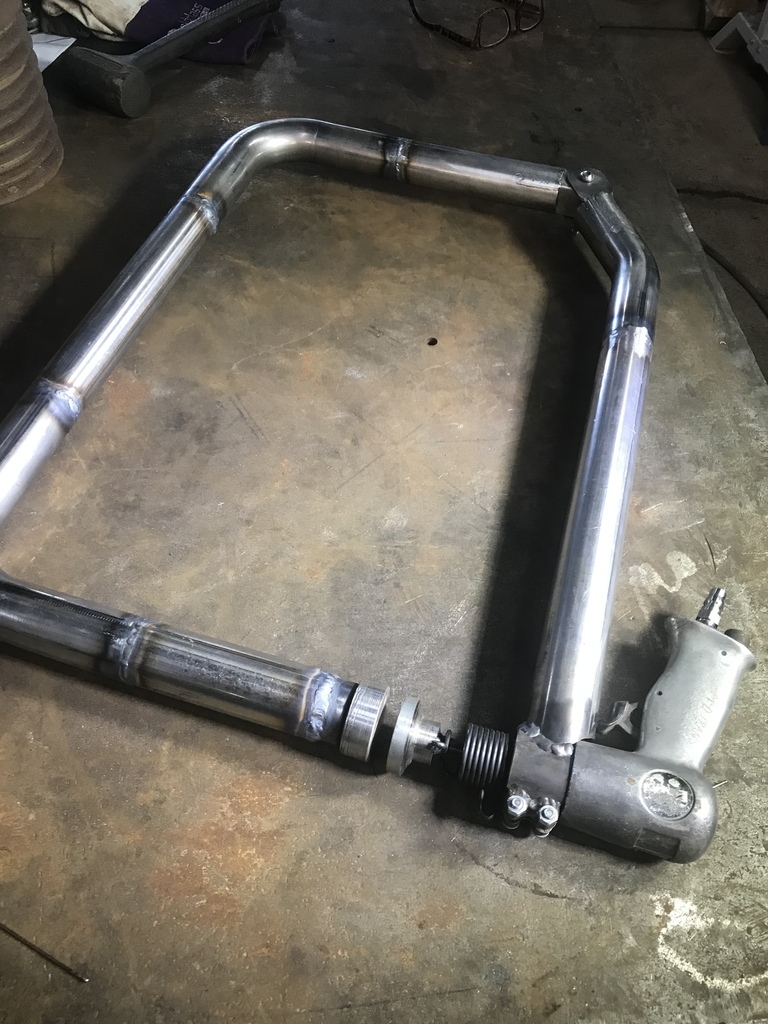 One side of the adjuster bracket was next. It will be trimmed to size once some geometry is worked out. 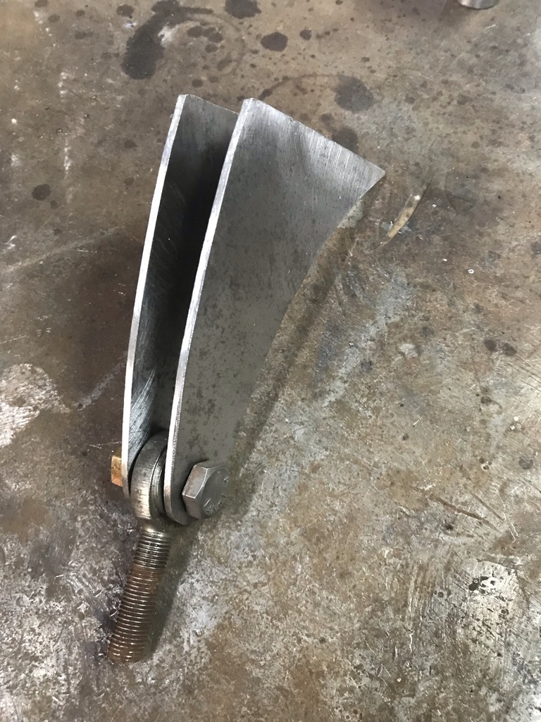 Working out the shape of the other adjuster bracket. 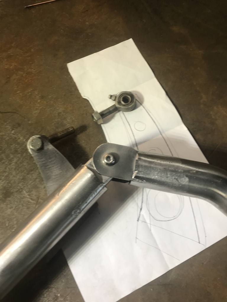 The finished adjuster brackets with the screw adjuster. Left hand thread on one of the rose joints. 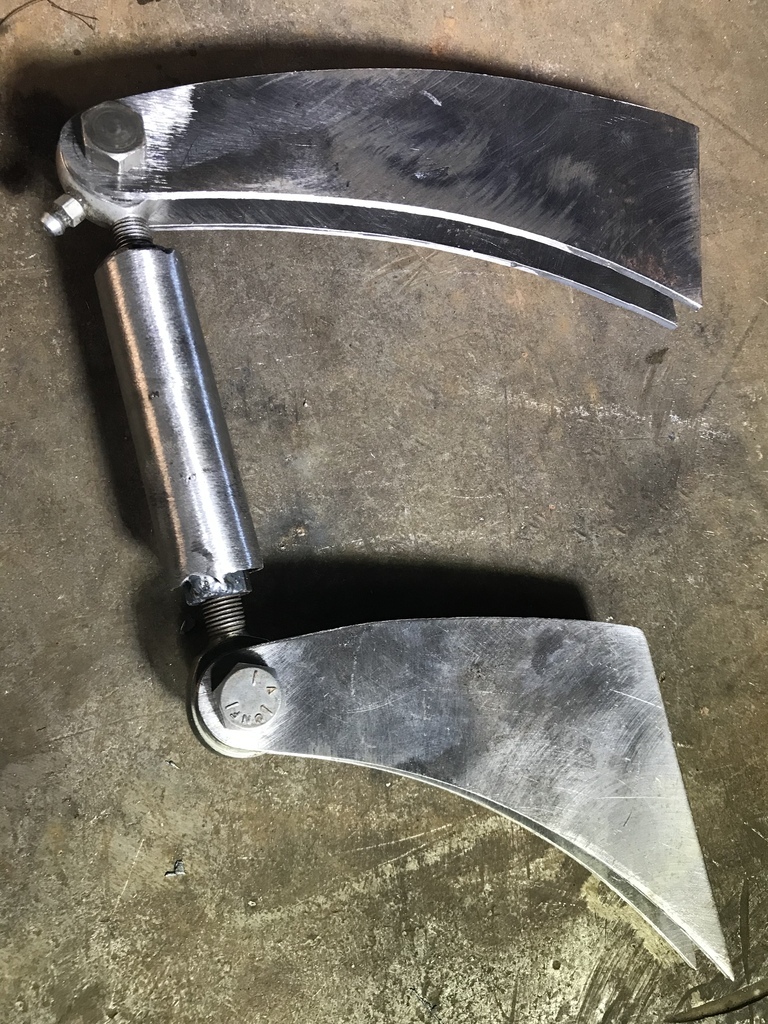 After cutting to size, positioned and ready to tack. 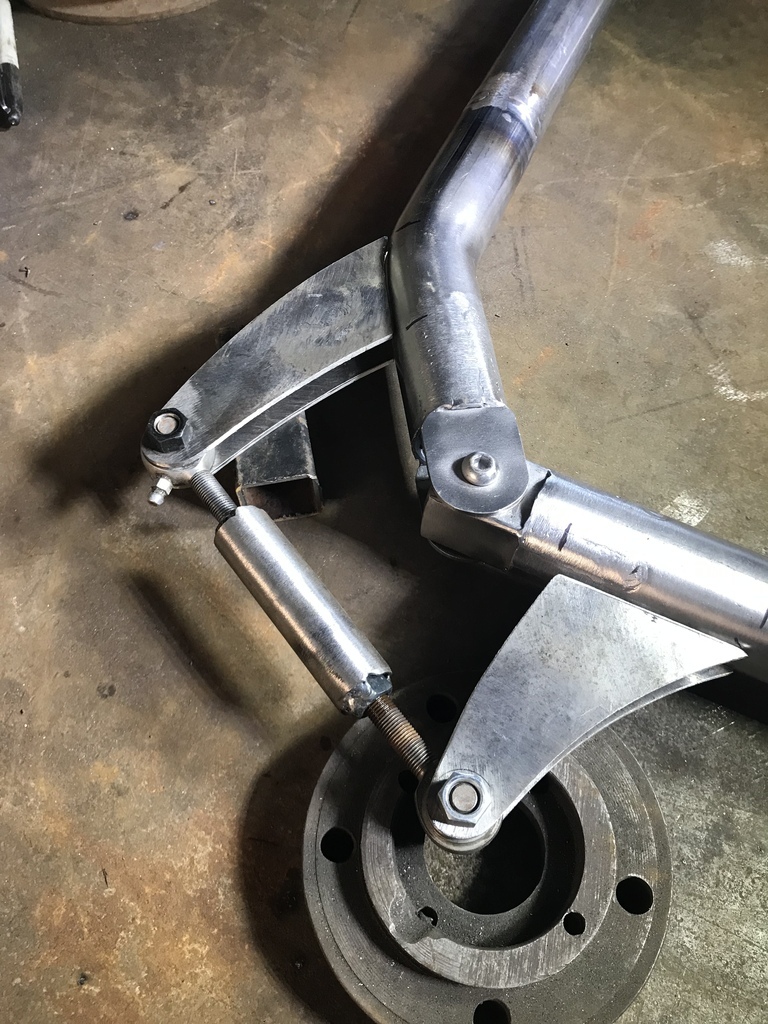 Check the movement and the weld fully. 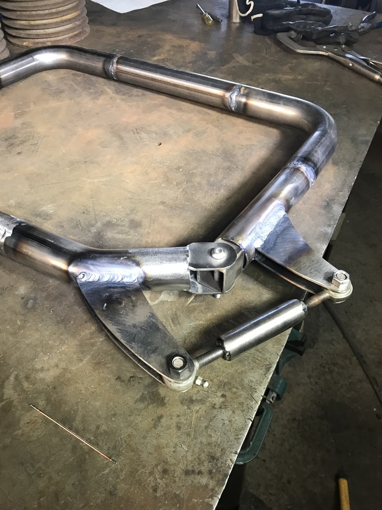 The finished tool. 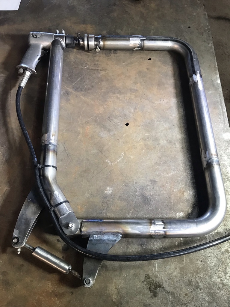 I haven’t used it on the car yet because the body is back on the chassis but I tried it on a piece of scrap and it seems to work well. Once I have the body back on the rotisserie, I’ll try it properly. That’s all for now. Comments and queries welcome. Cheers Garry |
| |
|
|
|
|
|
|
|
Jul 23, 2021 12:51:12 GMT
|
|
|
| |
|
|
gazzam
Part of things
 
Posts: 741 
|
|
Jul 26, 2021 11:48:56 GMT
|
Thanks John, shame I’m a bit far away, you’d be more than welcome to borrow it! I have the body off the rotisserie and back on the chassis. Now that the rh front guard is done, apart from metal finishing, I need to get the front bumper mounts sorted. The passenger side had only one original hole. The other was only a pilot hole in an area that I had patched. Circled here. 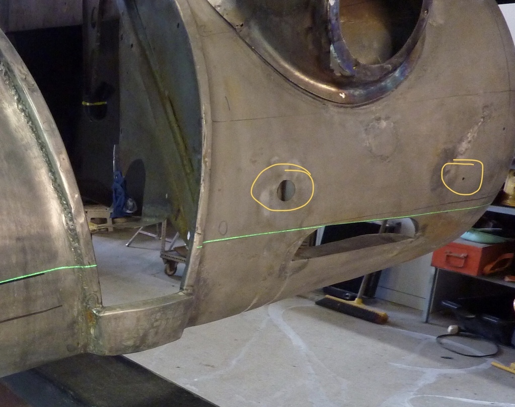 I wasn’t sure that either of these would line up with the bracket behind them. The bracket, known as the cowhorn because of it’s shape, was pretty badly knocked around and needed a fair bit of work. So I was surprised to find that this hole lined up! Amazing when you recall that almost every part in the vicinity has been repaired to a lesser or greater degree. The stars must’ve come into alignment! Used the laser to get a line to check the the holes for the driver’s side. This was after I had used a long centre punch through the mounting holes from the inside to mark them. 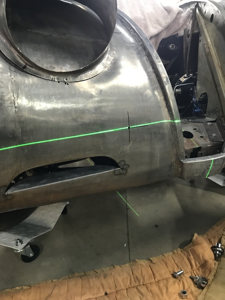 One of the existing irons was original, and in good condition.The other was neither. It was from the wrong size steel and badly out of shape. That’s the poor one on the right in this photo. And the replacement underway on the left. 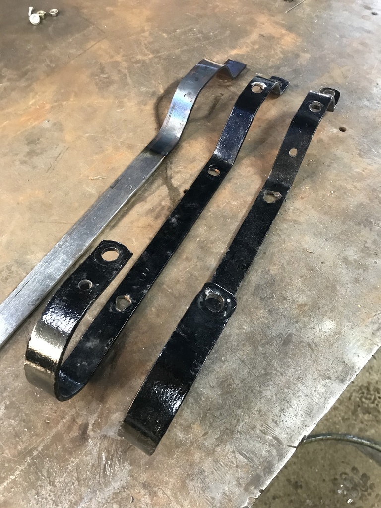 Bends finished on the replacement. 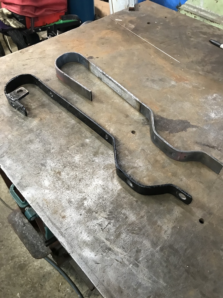 Pilot holes drilled, need opening up to 1 inch. This allows a bit of adjustment on the final location of the hole. 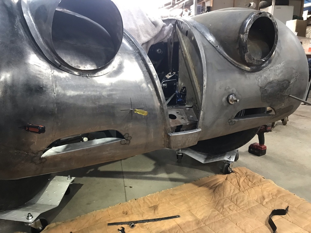 All four mounts in place. 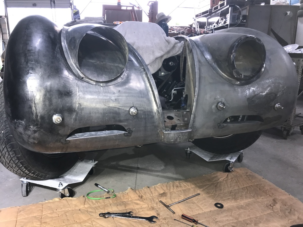 And the replacement iron in place. Needs holes for bumper bolts. 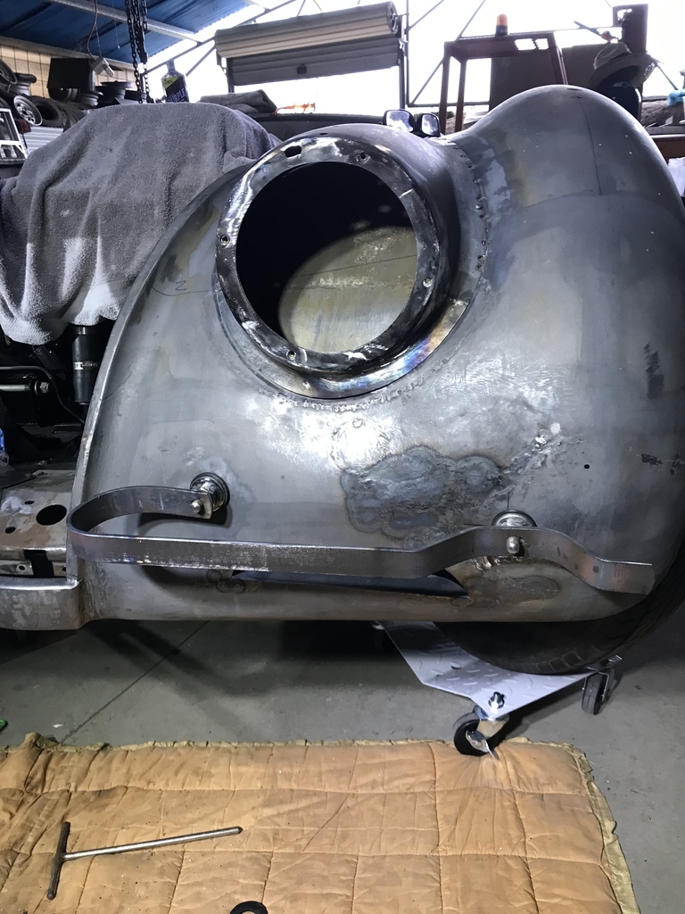 We have bling: 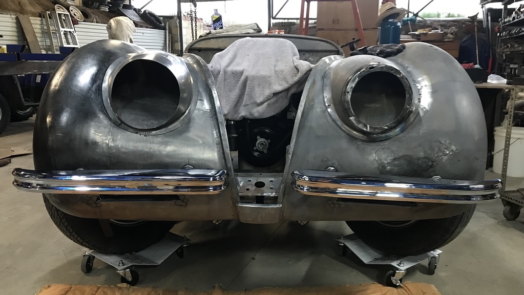 That’s all for now, comments and queries welcome. Cheers Garry |
| |
|
|
|
|
|
Jul 26, 2021 12:58:38 GMT
|
|
I know it's probably just perspective, but it really looks like they're both sagging a bit.
Even from multiple angles!
Does the laser/level 'make the noise' on the bumper?
Or is it meant to be angled?
Looking great though!
|
| |
Last Edit: Jul 26, 2021 13:00:40 GMT by varelse
|
|
|
|
|
Jul 26, 2021 13:09:12 GMT
|
|
Thank you Gazzam. I don't actually have a use for it at the moment but I love tools, particularly old and well made ones and if one comes up at the right price I'll snap it up.
|
| |
|
|
|
|
|
Jul 26, 2021 13:14:04 GMT
|
|
I think the "sagging look" is due to the camera lens...As I have said before - this XK is more accurate than Jaguar ever made back in the day!
|
| |
|
|
gazzam
Part of things
 
Posts: 741 
|
|
Jul 27, 2021 11:30:56 GMT
|
I know it's probably just perspective, but it really looks like they're both sagging a bit. Even from multiple angles! Does the laser/level 'make the noise' on the bumper? Oh ye of little faith. Seriously though, no one was more surprised than me when the straight edge sat (pretty much ) evenly on the bumpers. 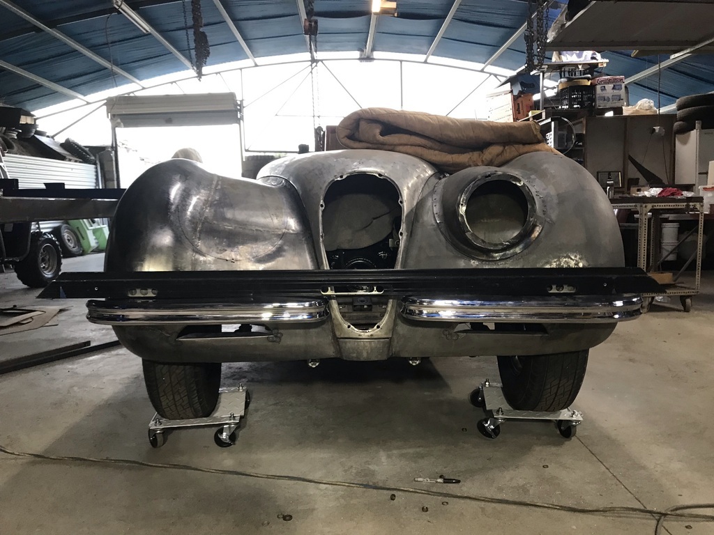 I don’t know what you mean by multiple angles though. This angle shows how they don’t sit flat across the front. 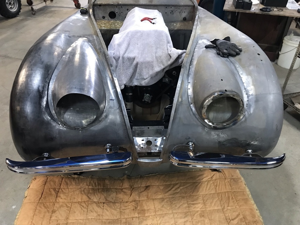 |
| |
|
|
|
|
|
|
|
|
The proof is in the pudding!
Mmm.. pudding.
Thanks for putting the level on it to quieten the voices in my head!
|
| |
|
|
gazzam
Part of things
 
Posts: 741 
|
|
Jul 30, 2021 12:40:57 GMT
|
Started on the exhaust. I want a dual system, 1 pipe from each manifold. So it will effectively sound like two three cylinder engines. That’s what it had before, but one pipe went through the hole that had been hacked into the cross member. I repaired that damage and unless I run the pipes under the cross member ( which I don’t want to do ) two pipes must go through the one remaining ( original ) hole. But two 2” pipes won’t fit through the hole. So I thought I would make a 3 inch pipe with a divider up the middle and two 2 inch pipes on each end. Half of a 3” pipe has a slightly larger cross section than a 2” tube. So I need to make the 2” to half-a-three-inch adapters. First I made a press tool from a piece of 3 inch steam pipe cut in half. It was welded to some inch and a half pipe that I’d turned down to fit inside 2” exhaust tube. Various bits of flat were welded on and ground back to end up with this: 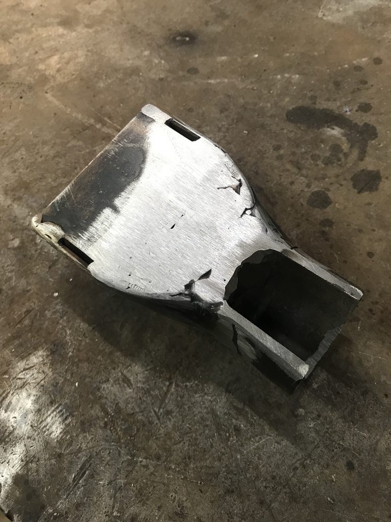 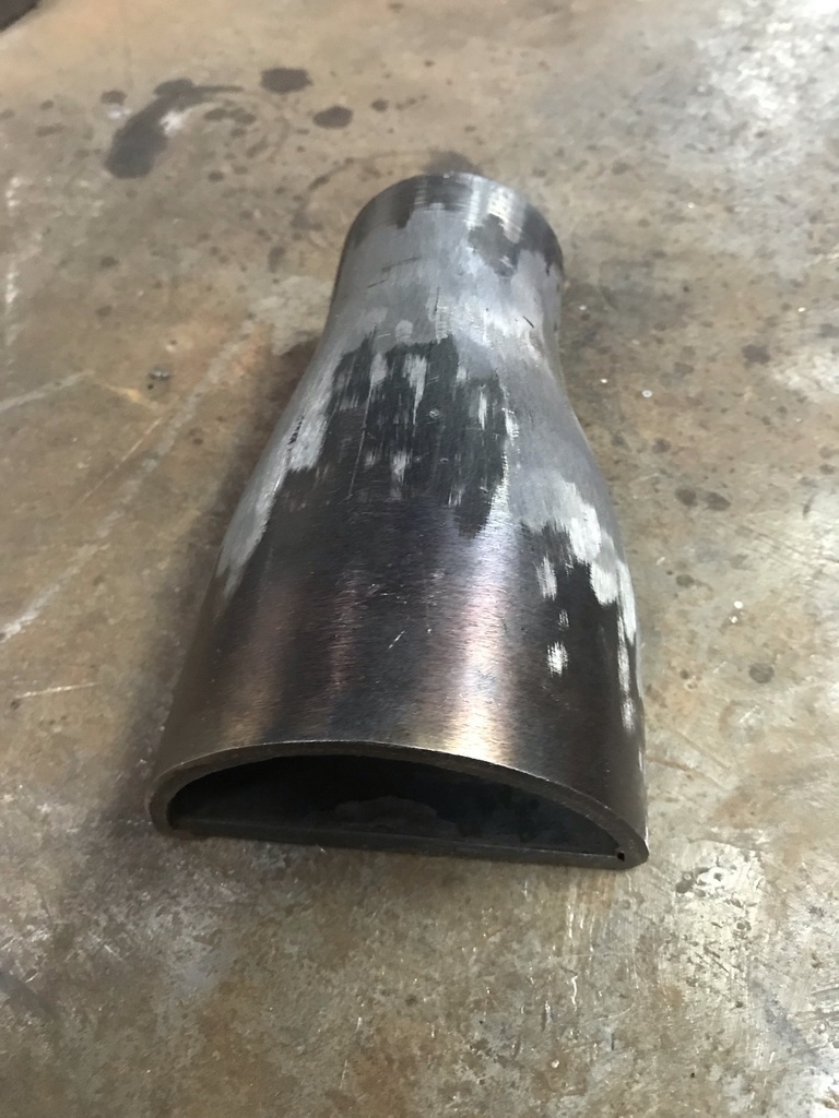 When pressed into a piece of 2” stainless tube you get this: 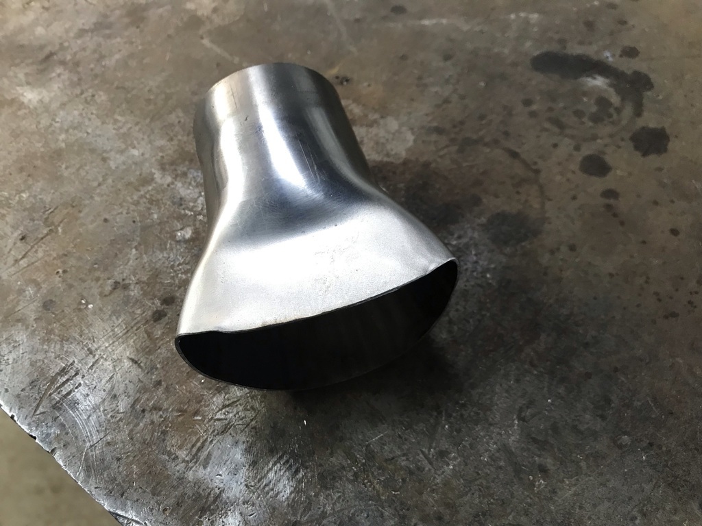 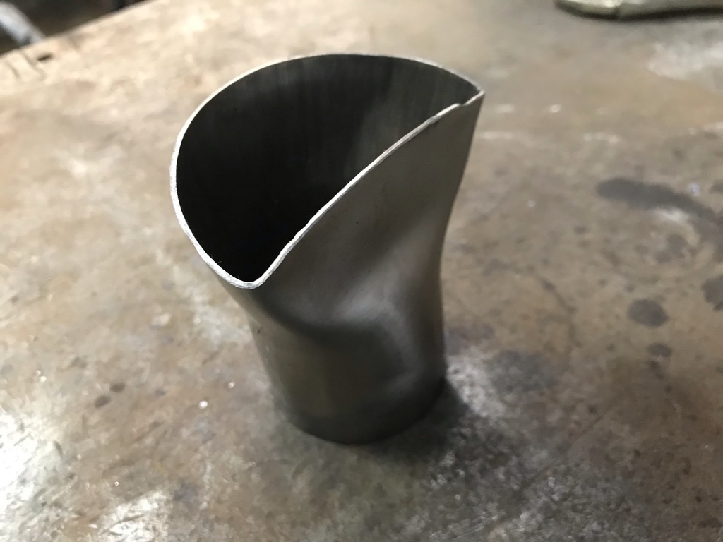 And then there were four. Plus 1 that split - I learned to put the seam away from the most stretched area. 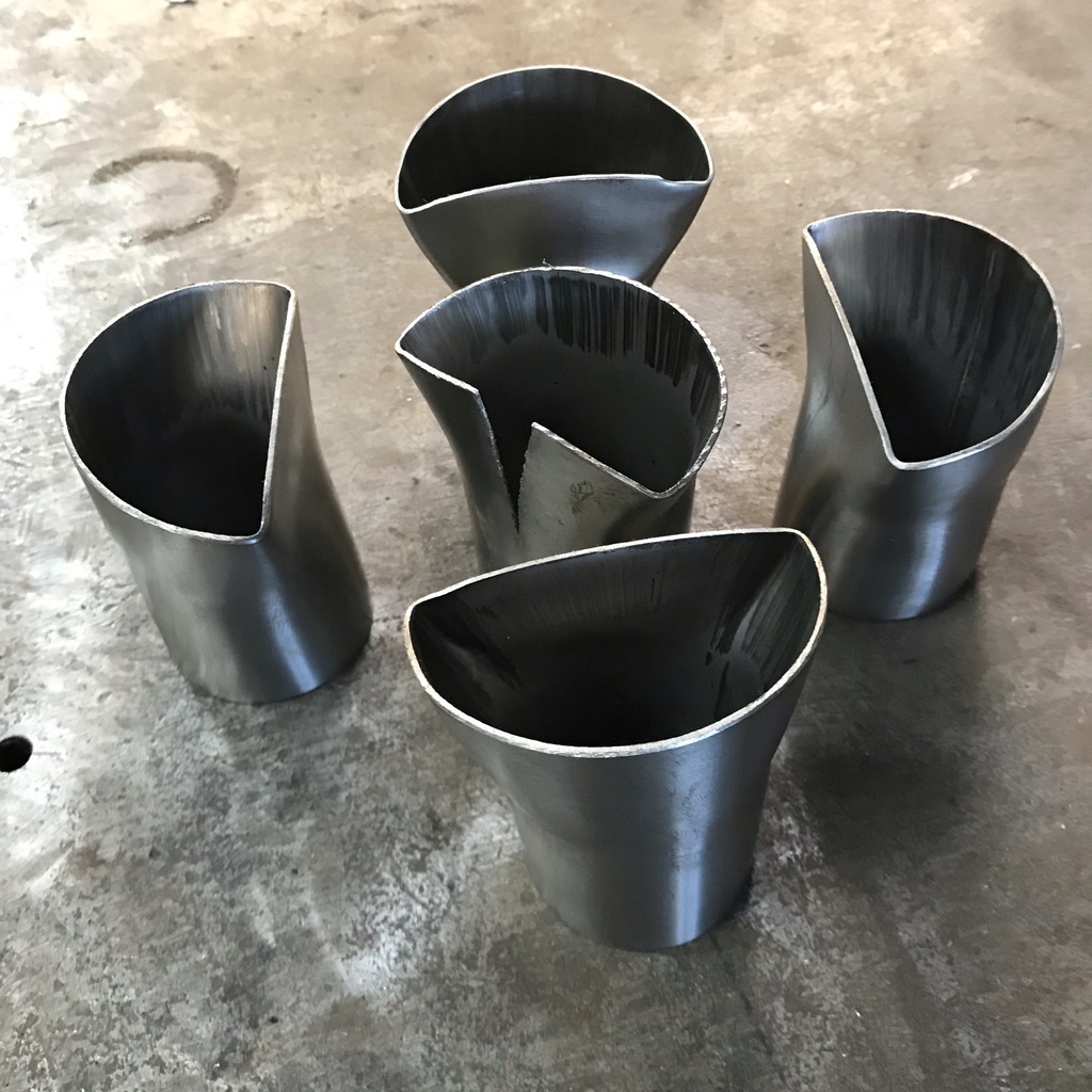 Which gives me a start on this fairly complicated piece. It has to have two x 2” inlets on one end, fit within a 4” pipe through the chassis and have a sealable, detachable end with two x 2” outlets. Take a bit of 18g stainless 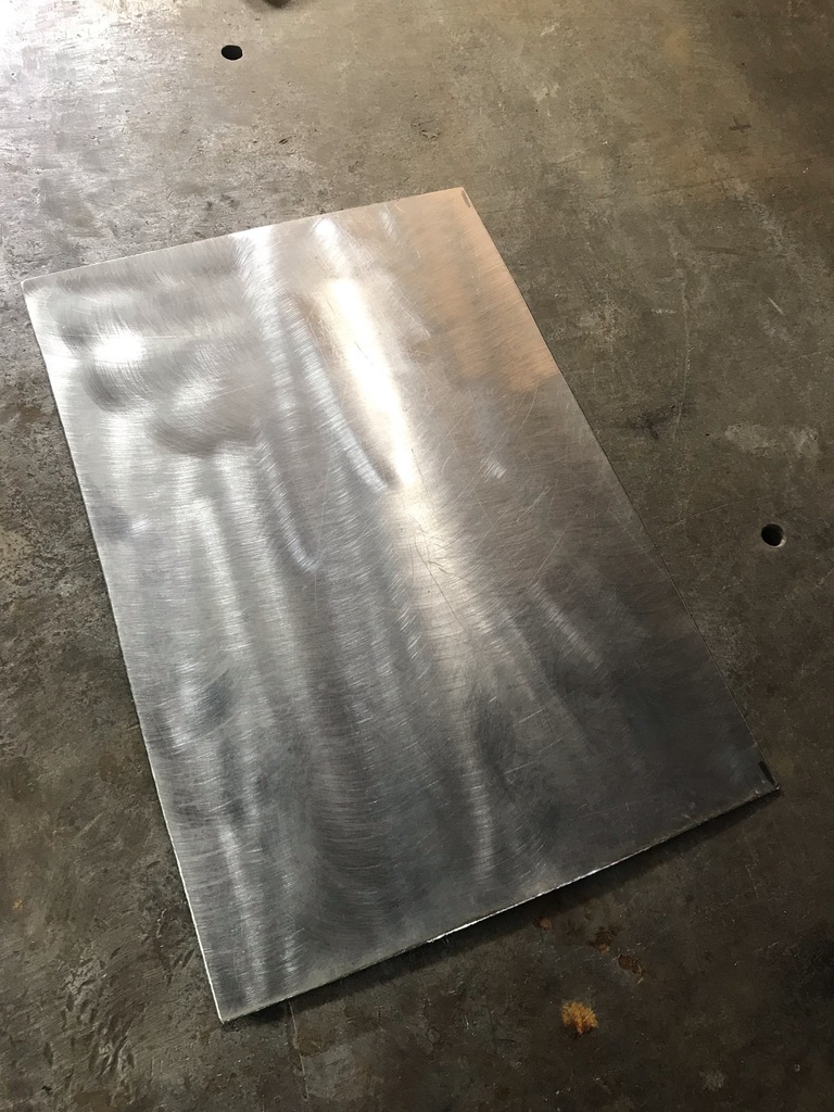 Roll it into a tube. 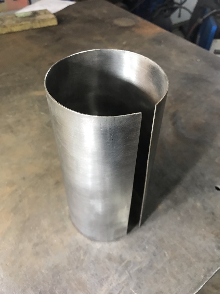 Cut the tube into two. 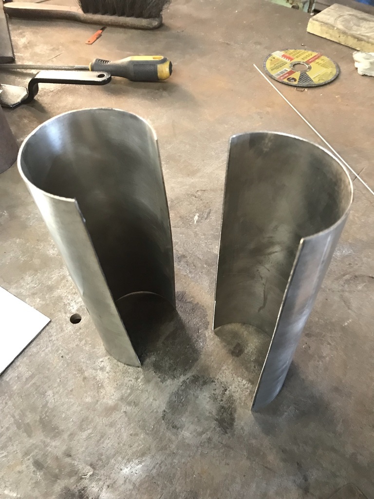 And match it up to the end pieces. Just tacked to get the fit ok. 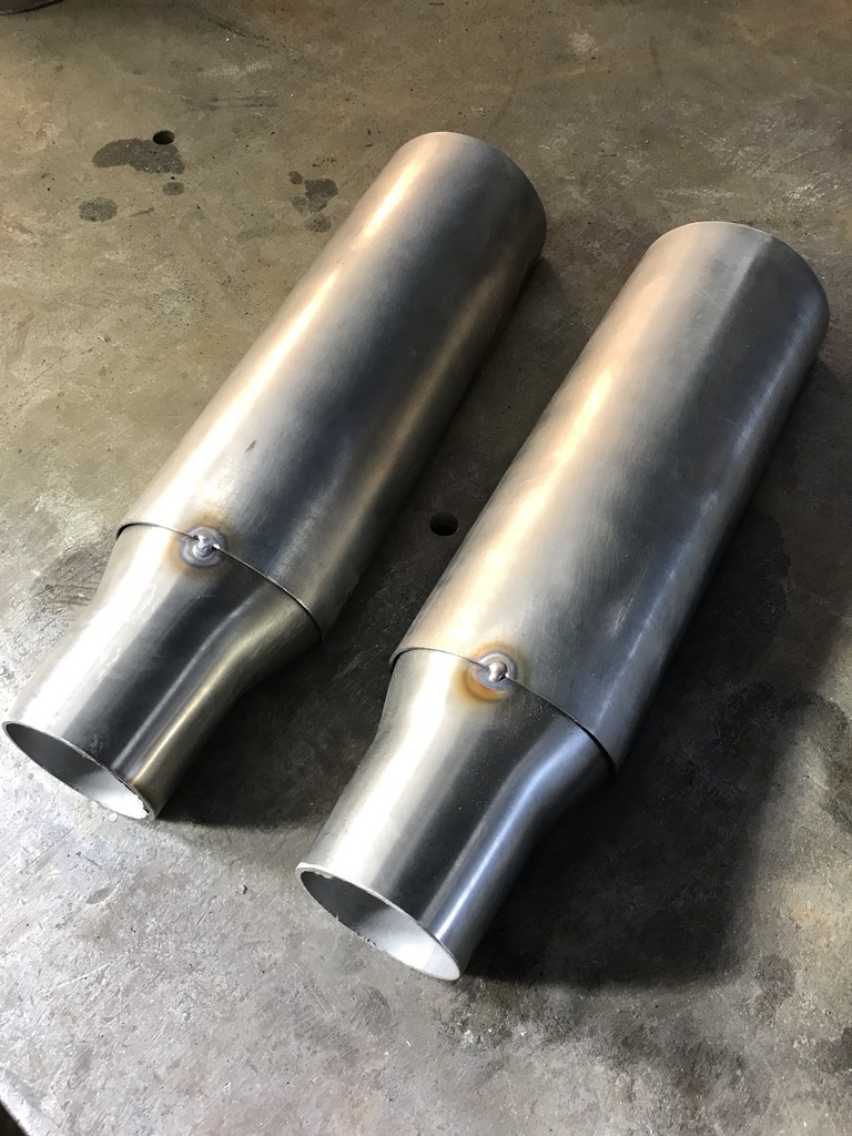 Then the formed pieces can have extensions welded to them, after the half tubes have been untacked. 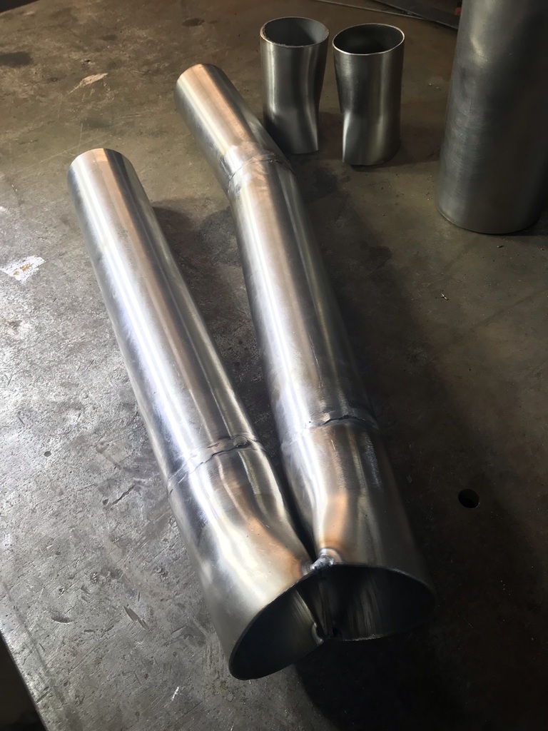 And a divider can be welded on. 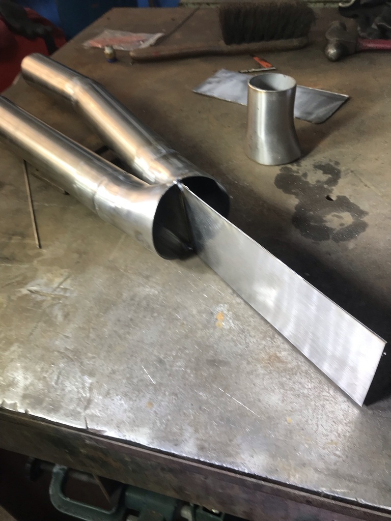 Then the half tubes can be reattached. 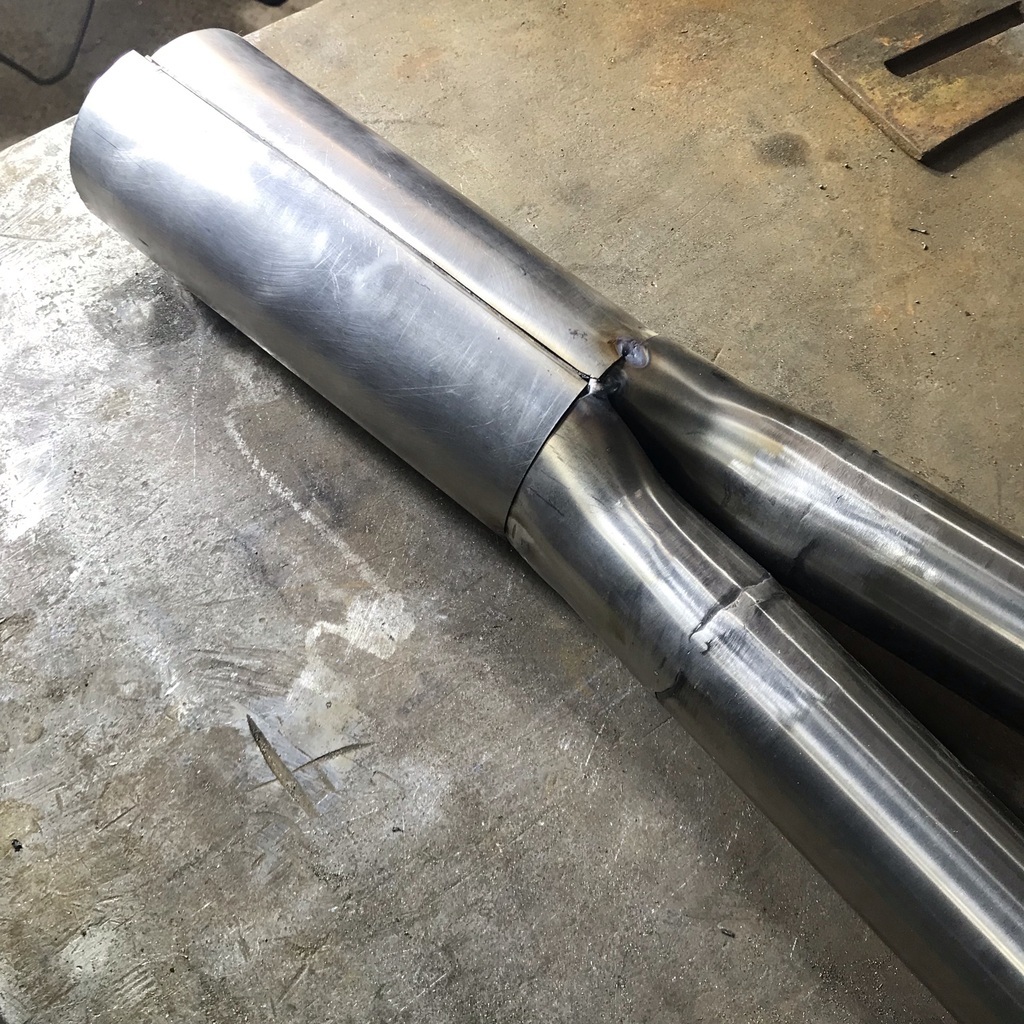 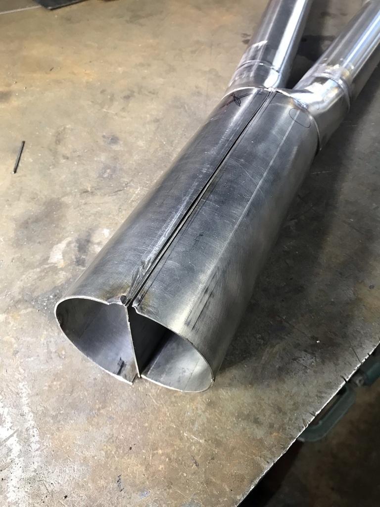 And fully welded. 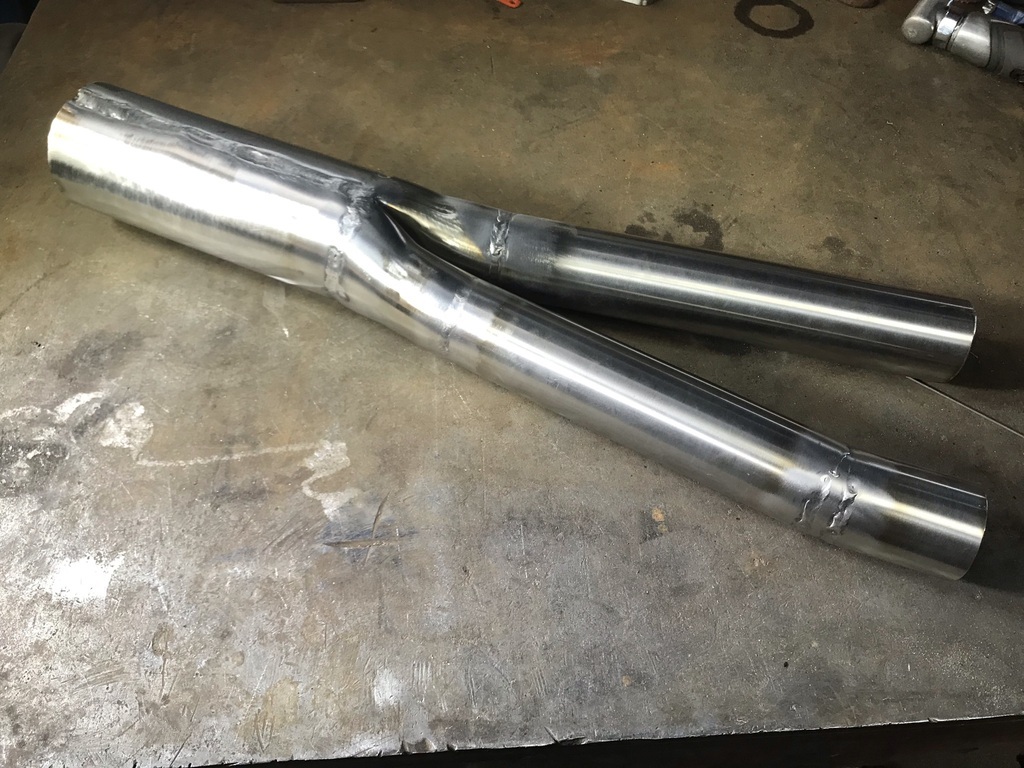 And it goes here. 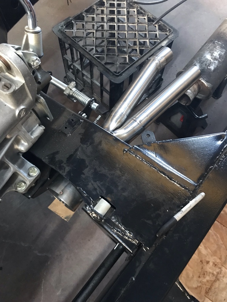 Hope that makes sense. That’s all for now. Comments and queries welcome. Cheers Garry |
| |
|
|
|
|
|
Jul 30, 2021 13:08:20 GMT
|
|
Absolutely brilliant. Well thought out and beautifully executed. I love it.
|
| |
|
|
|
|
Zagato
Part of things
 
Posts: 80
|
|
Jul 30, 2021 14:16:35 GMT
|
|
I haven’t heard of splitting a straight 6 exhaust into 2 threes as being desirable before?
Always thought the straight 6 purr was best 🤔
|
| |
1959 Abarth Double Bubble resto project
1989 Lotus Esprit LHD
1997 Lotus Eprtit GT3
1996 Jaguar XJ6 Sovereign manual gearbox from factory
Porsche 356A Coupe replica
Formula 27 Super Seven replica Alfa Nord powered
|
|
gazzam
Part of things
 
Posts: 741 
|
|
Jul 31, 2021 20:39:34 GMT
|
|
Thanks John, it’s a lot of work just to avoid pipes going under the cross member but also an interesting little project. If it works that is.
Zagato I can’t remember where I read that about the two x three cylinder thing but the two separate manifolds certainly makes it easy to do.
i used to have a Triumph dealership and their thing is three cylinder motors. And I’m well aware how good they can sound.
But sound depends on firing order among other things,and that’s probably totally different, so it could all be curse word. But the car sounded good before, so hopefully will again.
|
| |
Last Edit: Jul 31, 2021 20:41:22 GMT by gazzam
|
|
|
|
|
|
|
|
Is there enough space to pick and choose your cylinder groups? Or are you stuck with just 1-3 and 4-6?
|
| |
|
|
|
|
|
|
|
Thanks John, it’s a lot of work just to avoid pipes going under the cross member but also an interesting little project. If it works that is. Zagato I can’t remember where I read that about the two x three cylinder thing but the two separate manifolds certainly makes it easy to do. i used to have a Triumph dealership and their thing is three cylinder motors. And I’m well aware how good they can sound. But sound depends on firing order among other things,and that’s probably totally different, so it could all be curse word. But the car sounded good before, so hopefully will again. The 1960's S-Type splits the exhaust in two and brings one out of each side of the car and the MK2 is effectivly two exhausts fixed together with two tail pipes next to each other (except for the basic 2.4 which is a single pipe). |
| |
|
|
gazzam
Part of things
 
Posts: 741 
|
|
|
|
Is there enough space to pick and choose your cylinder groups? Or are you stuck with just 1-3 and 4-6? The manifolds dictate the layout. 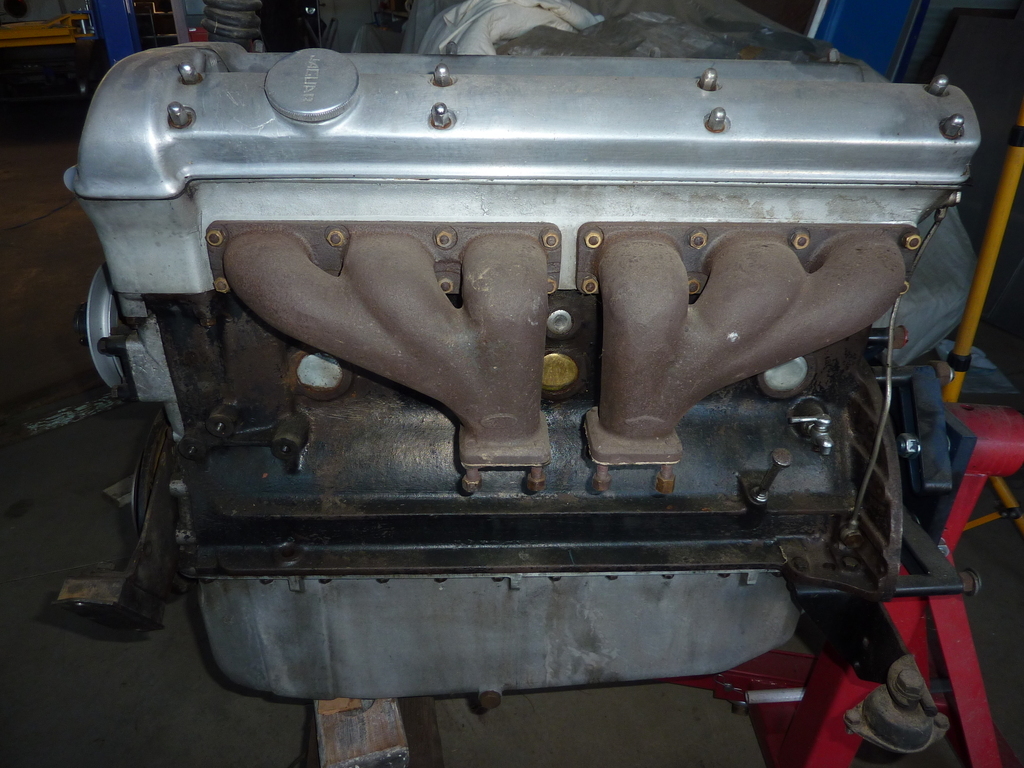 Still working on the exhaust, just wasn’t keen on more bodywork. So the outlet part of the collector or whatever it’s called, the bit that goes through the cross member, was done. Next is the inlet part. Basically a 2 by 2 inch into 3 inch cap. With a divider. First a piece of 18 gauge stainless. And deja vu, roll it into a tube. 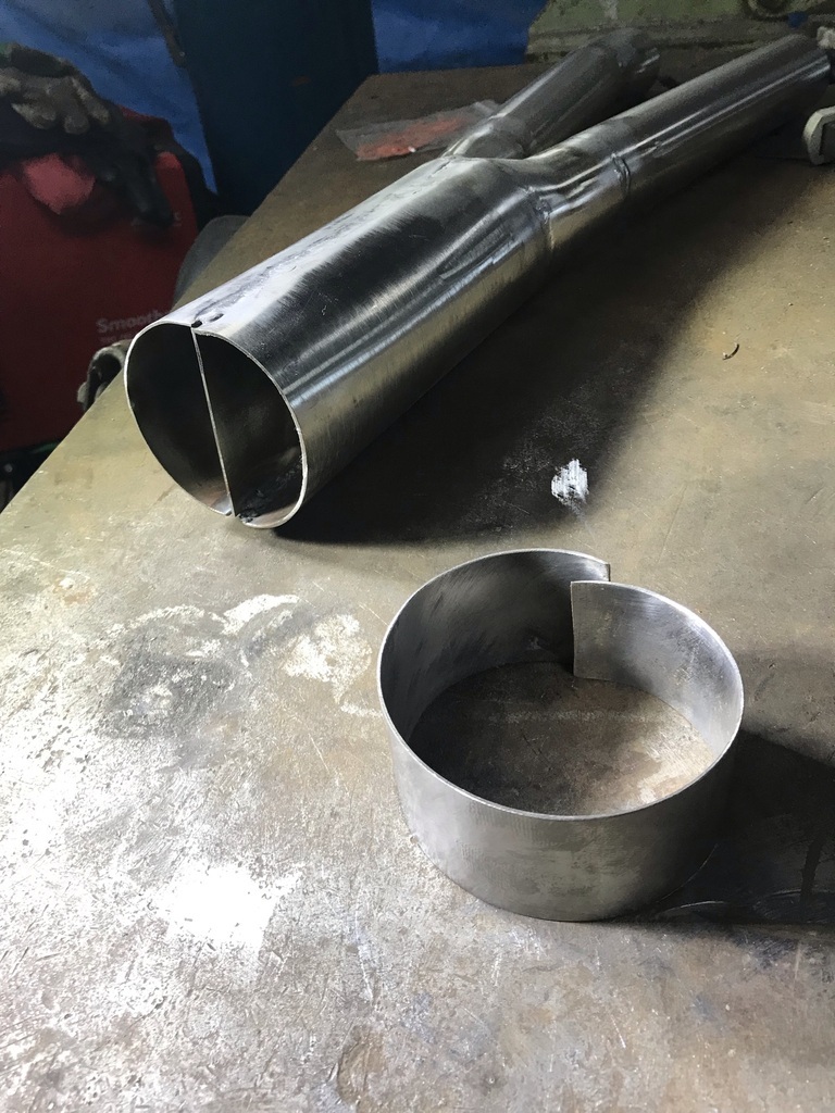 Well, sort of a circle. Anyway it was the right shape when a hose clamp held it around the collector. 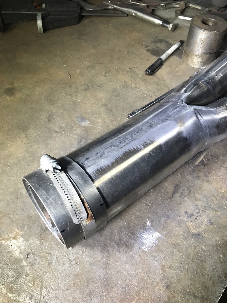 Then it was marked and cut to length. Then clamped on to be tacked. 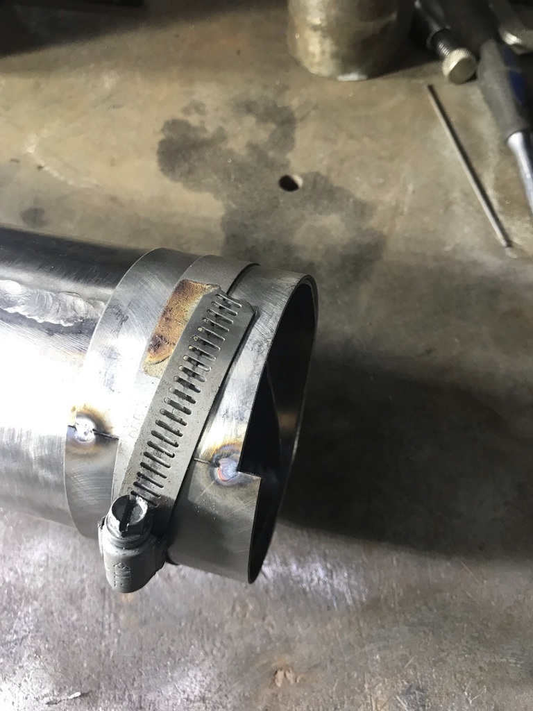 The collector needed building up with weld, to make it into more of a circle, so the cap might fit nicely. 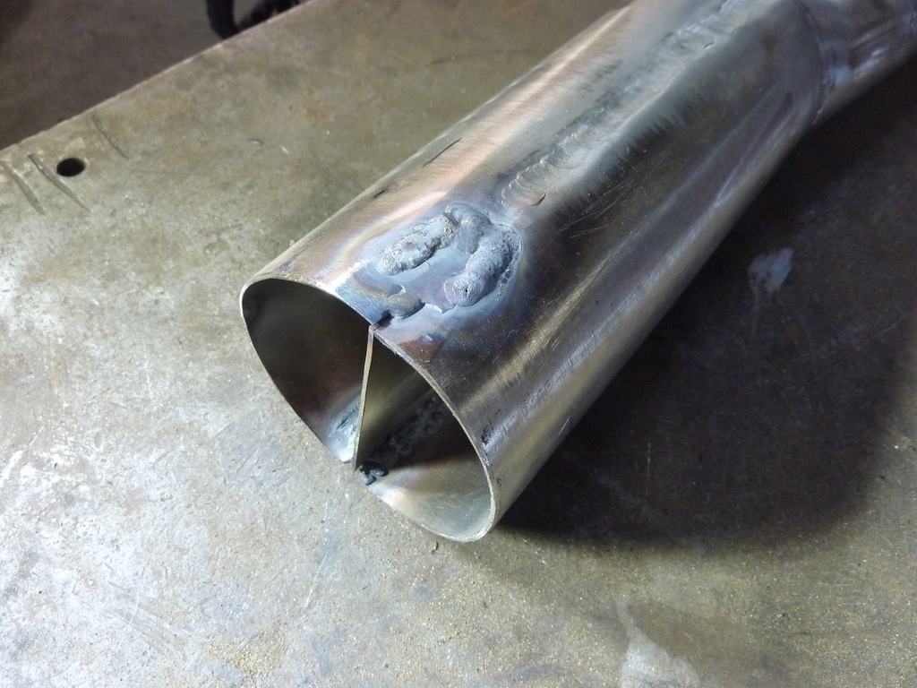 Then ground back. 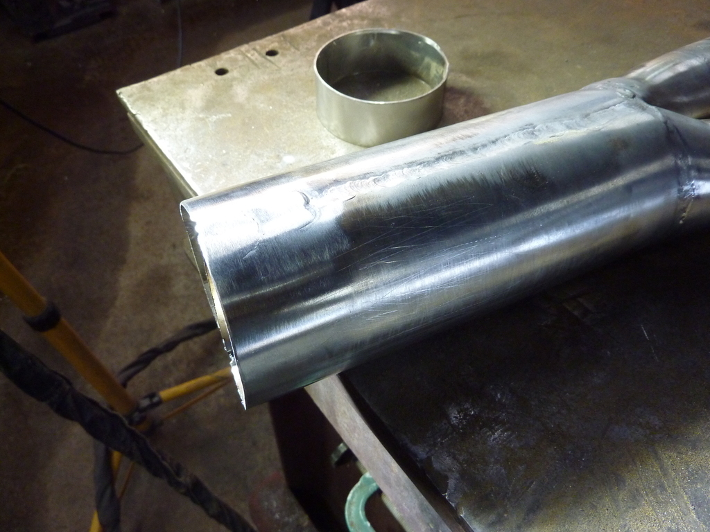 Then a small piece of stainless welded to one of the 2 inch bits, to ensure the cap lines up with the divider. Maybe a few photos can tell this bit of the saga. 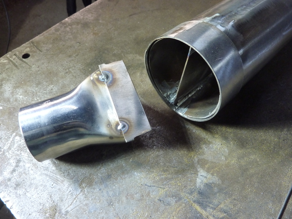 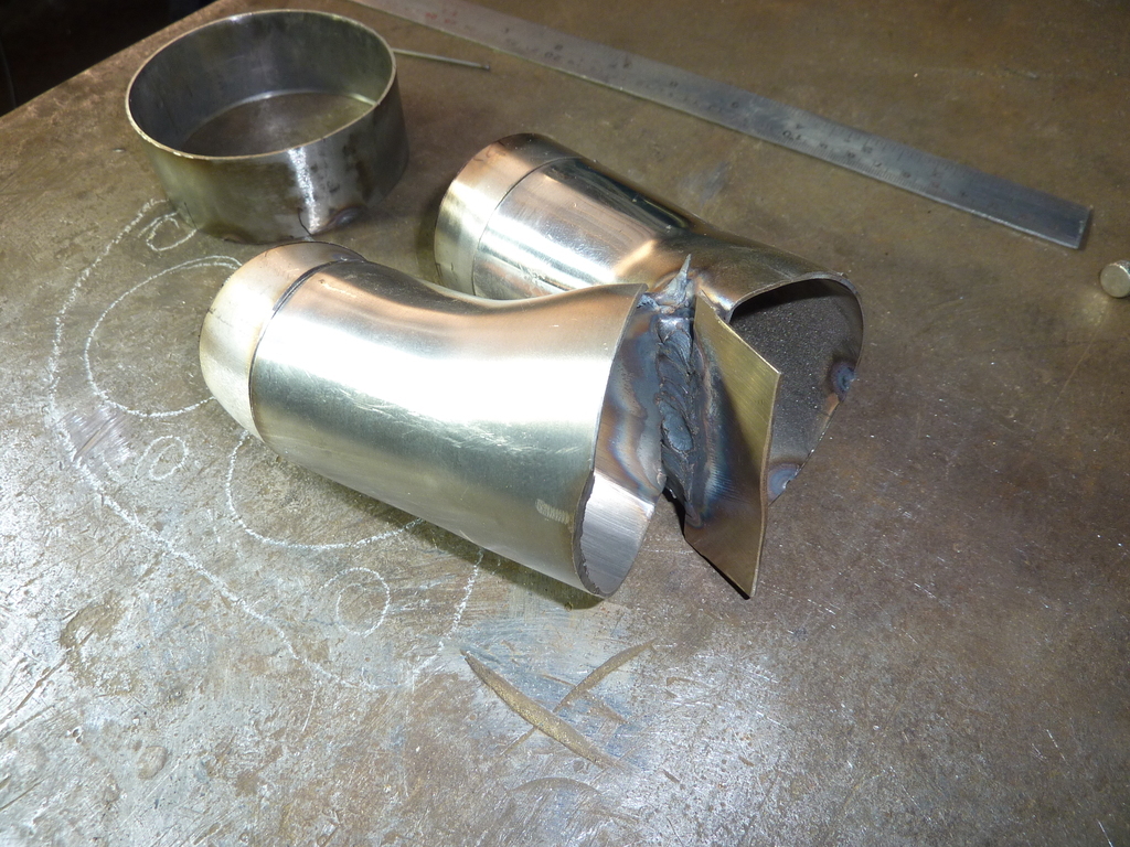 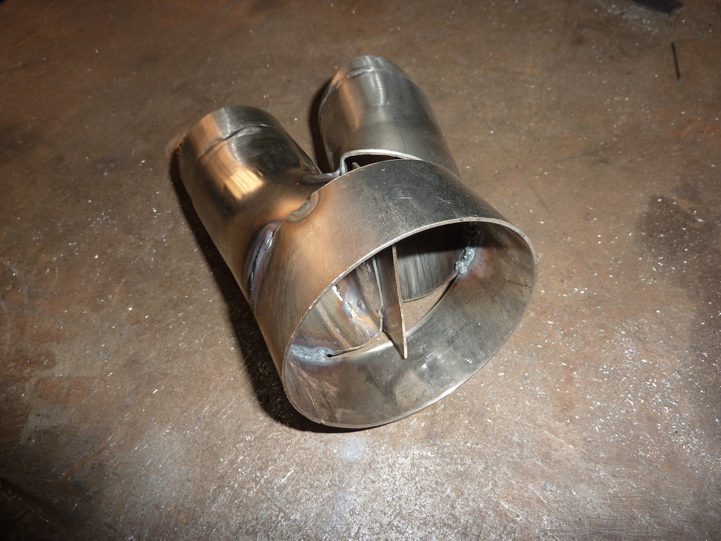 A flange for the inlet was next. A piece of 5mm stainless with a couple of holes courtesy of the plasma cutter. 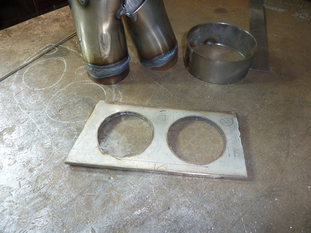 Times two. I hate drilling stainless. Also this was a bit of a mistake. I should have made it to suit an available gasket. I didn’t, now I have to find something to make one from. Maybe some annealed aluminium? 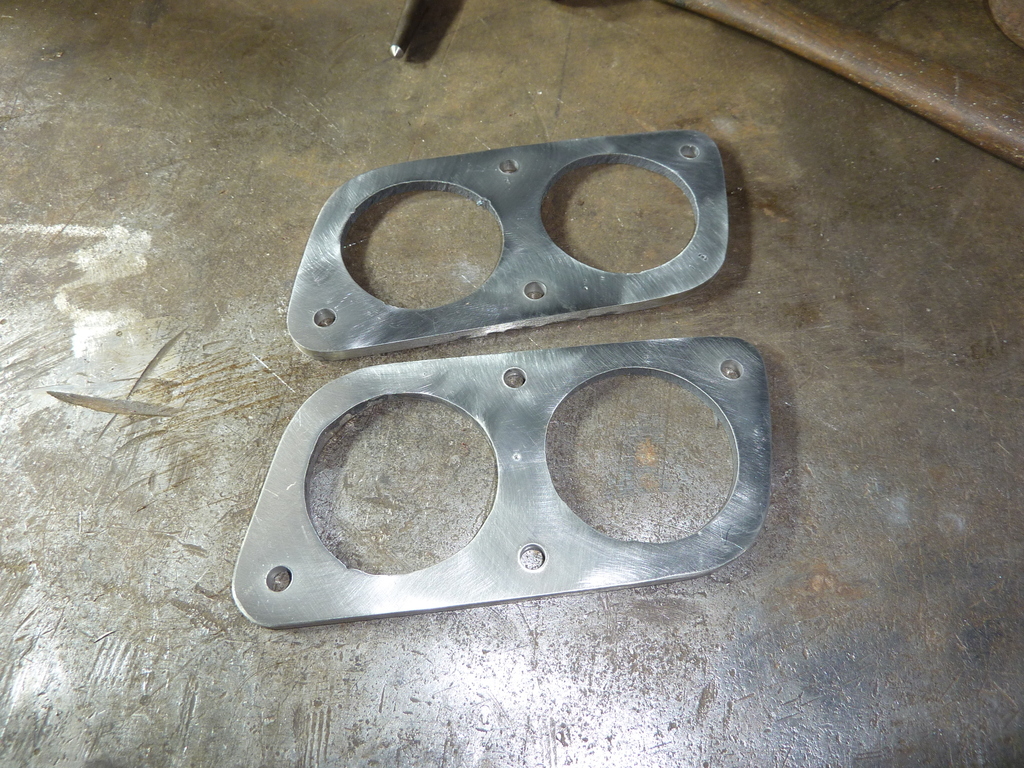 The 2 inch adapter ( or whatever I’ve called them before) that split came in useful. I had to splay one of them out to get a gap so there was room to get a welder in there. This left a gap. Circled in this photo. Used a piece of cardboard to get a template ( also circled) and cut bits from the split one to fill the gaps. 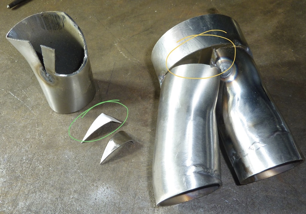 Welded and a visit to the bead blaster to make my welds look a bit better: 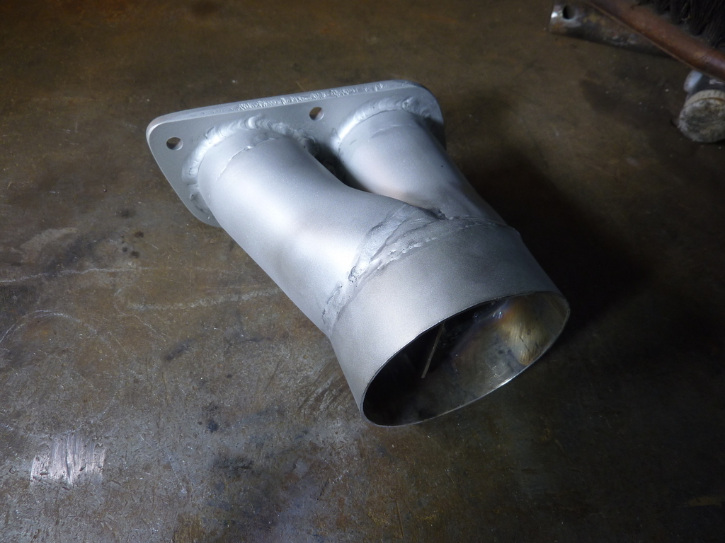 That’s all for now. Comments and suggestions welcome. Cheers Garry |
| |
|
|
|
|
|
|
|
|
Comment = brilliant work,
Suggestions = I wouldn't have the audacity, your work is of such a high calibre,
Nigel
|
| |
BMW E39 525i Sport
BMW E46 320d Sport Touring (now sold on.)
BMW E30 325 Touring (now sold on.)
BMW E30 320 Cabriolet (Project car - currently for sale.)
|
|
Zagato
Part of things
 
Posts: 80
|
|
|
|
|
Annealed copper makes an excellent gasket, many moons ago l used to make my own 4 stroke moped head gaskets using copper and a coping saw.
They never failed once....
|
| |
1959 Abarth Double Bubble resto project
1989 Lotus Esprit LHD
1997 Lotus Eprtit GT3
1996 Jaguar XJ6 Sovereign manual gearbox from factory
Porsche 356A Coupe replica
Formula 27 Super Seven replica Alfa Nord powered
|
|
gazzam
Part of things
 
Posts: 741 
|
|
|
|
Thanks Nigel. Good idea Zagato, I’ll keep my eye out for a bit of copper sheet. Last time I had finished the bits to take the exhaust through the chassis. Here it is in place with added bracket. 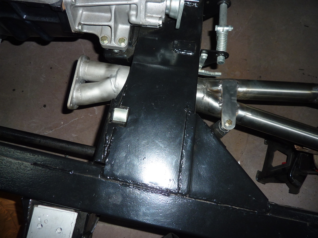 So now it’s time to make the downpipes. These are made up from a few 45 degree bends, various bits of straight and a flex piece. The flange is made from 5mm stainless. The very small bends are cut from a ‘donut’. The missing bit is how much it took to make these parts of the system ( minus a few mistakes ). 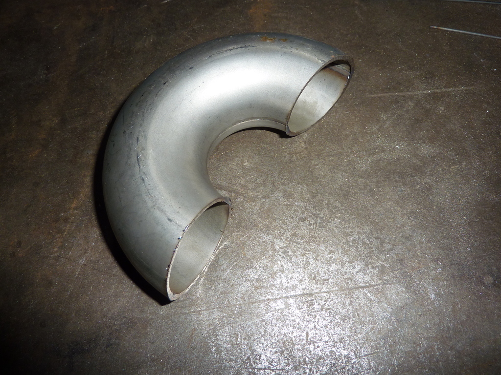 Here’s one tacked up after lots of on and off again, getting it to fit. 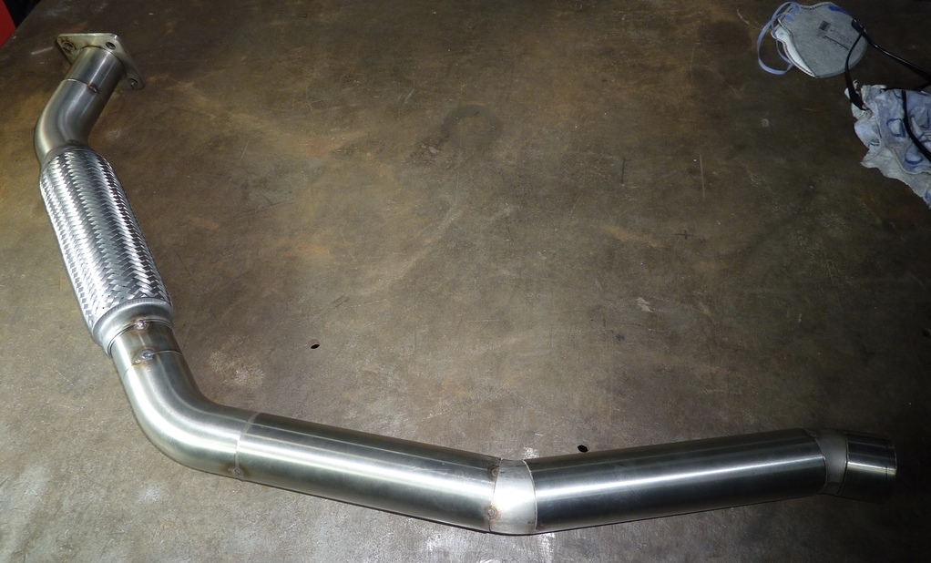 And the other one. 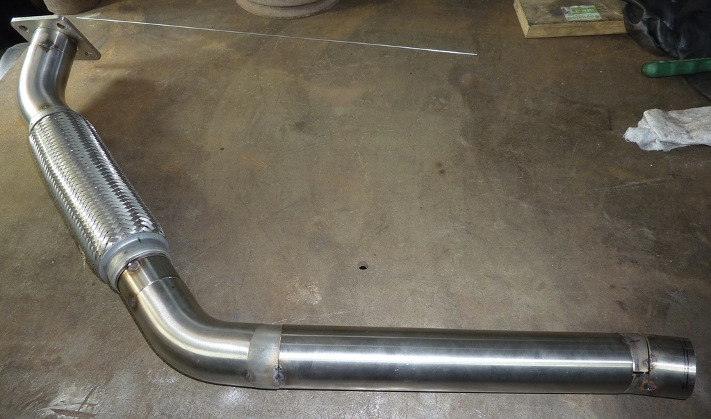 Trial fitting. 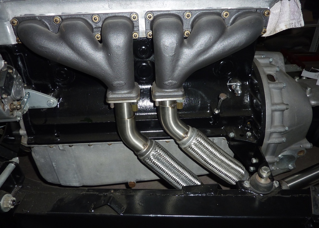 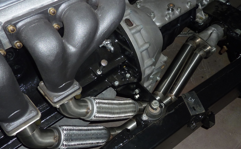 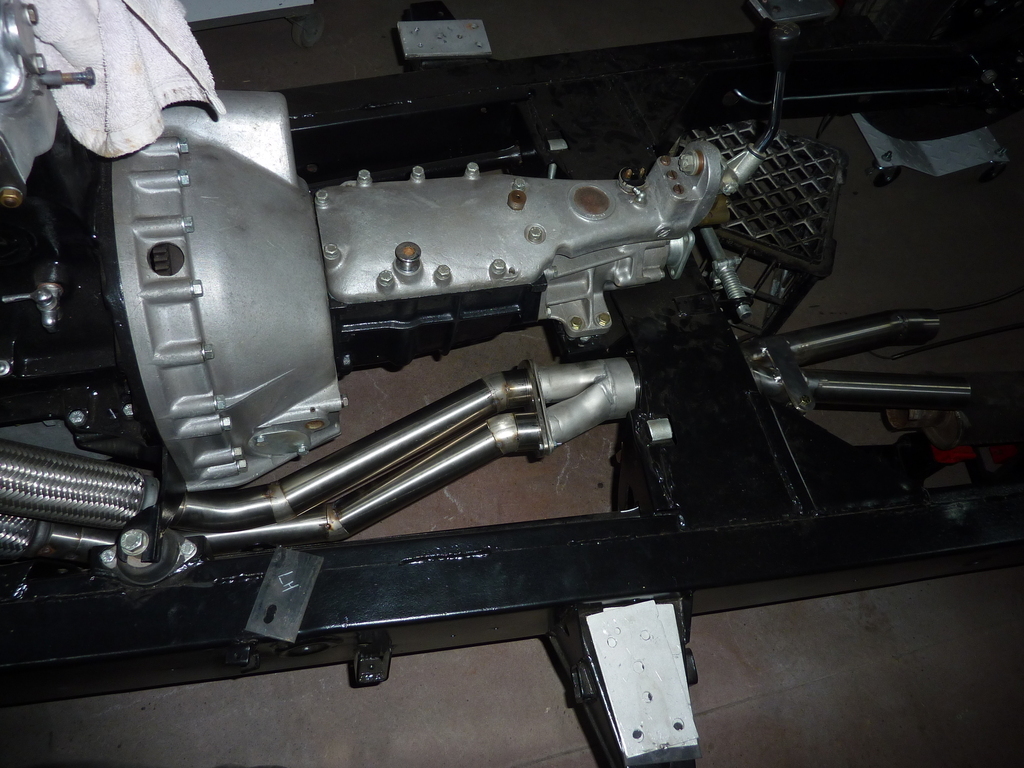 And after welding and cleaning. 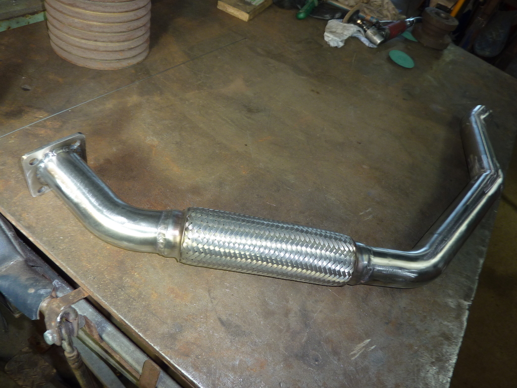 Now the pair are joined. The flange is not fully welded yet, just tacked. 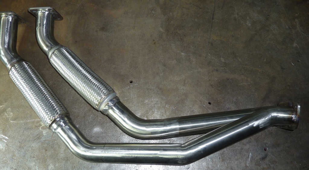 That part of the system is finished and the rest can wait till I can find some suitable mufflers. And probably better that I have the body on and the fuel tank installed to be sure of clearance. So it back to bodywork. Oh good… That’s all for now. Comments and suggestions welcome. Cheers Garry |
| |
|
|
glenanderson
Club Retro Rides Member
Posts: 4,357
Club RR Member Number: 64
|
1952 Jaguar XK120 restoration glenanderson
@glenanderson
Club Retro Rides Member 64
|
|
|
|
Lovely work, as usual. I’m assuming the flanged joint to the merged pipe is to make future disassembly easier?
|
| |
My worst worry about dying is my wife selling my stuff for what I told her it cost...
|
|
gazzam
Part of things
 
Posts: 741 
|
|
|
|
|
Well I hope I don’t have to worry about that, but it sure will.
Thanks Glen
|
| |
|
|
|
|


