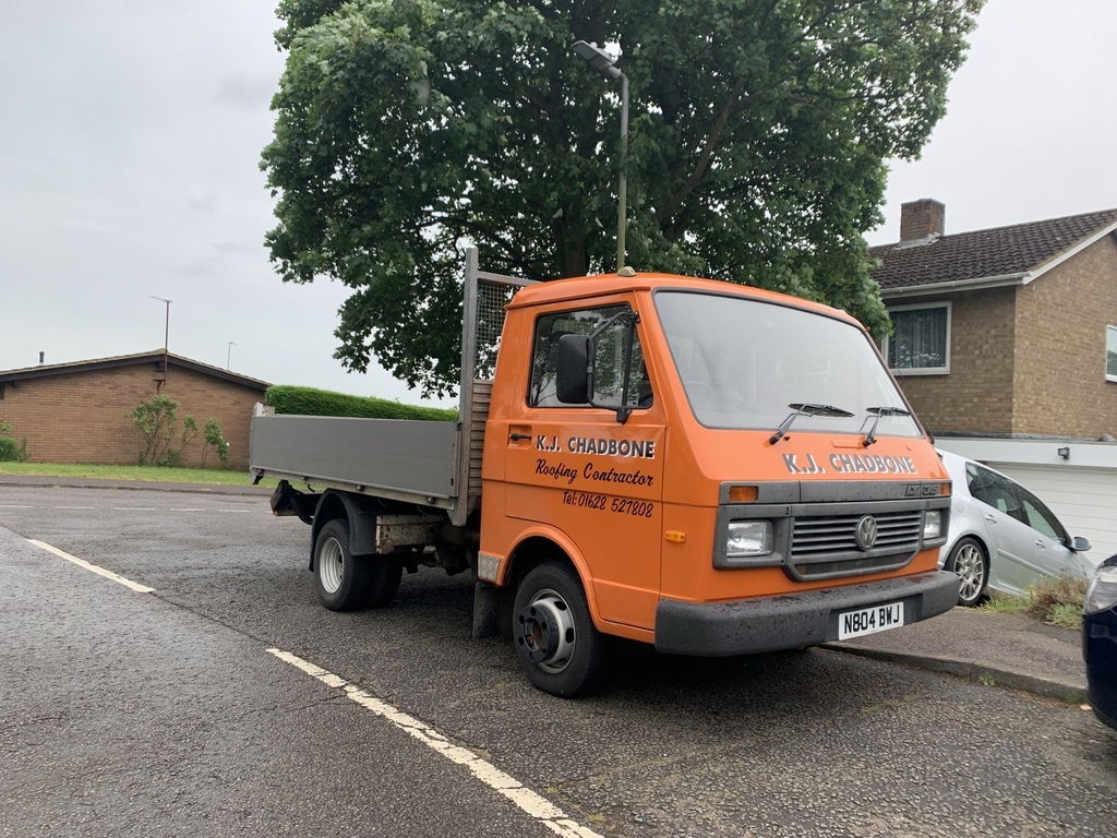
So....I've been super busy with the truck ( and loads of other stuff ) lately. I've been meaning to post an update for a few weeks now......but you know how it is 😁.
Today's update will show the work I carried out back in March/April according to the date stamp on the photos.
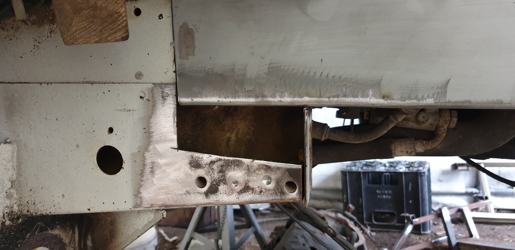
After tidying up and unpicking/drilling out what seemed like a million spot welds from the remnants of the old chassis section....it was time offer up the new section for the first time.
First impressions were good......
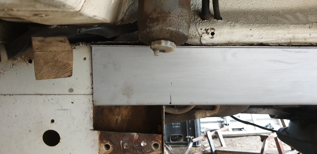
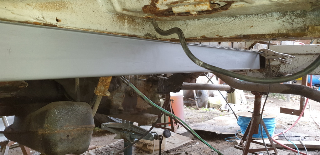
Now.....the width of the old chassis was 60 mm. When I picked up the new chassis sections from the company that was able to fold them, they did stress that the finished items were very slightly over. Apparently, the measurements I required were right on the minimum width of what their machine was able to fold at that thickness and depth. They mentioned a figure or 2 mm over, but once I got them home and measured them myself, they were a 4 mm maximum and 2 mm minimum out. Of course, that's only 2 mm max out each side of the when the lower is centered to the upper. But.....right at the front, the chassis is sat between a load of metal work for the steering idlers and the radius rod mounts......circled in the picture below.....
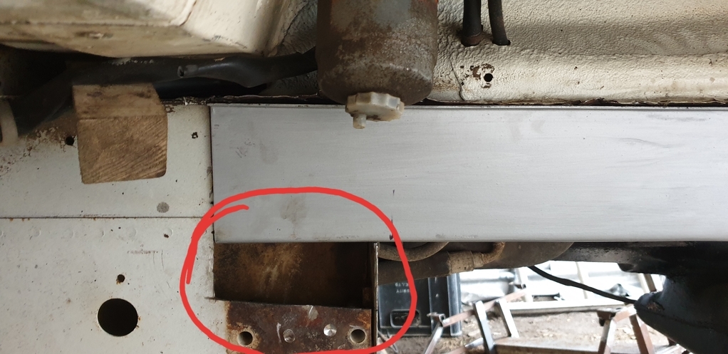
This means that it has to be the correct size at that point. So a decision was made to adjust the new 'slightly' oversized chassis sections at that point only. Then have the discrepancie along the outer side leaving the inner measurement between left and right chassis sections the same as it originally was. Meaning that I'd have to make adjustments to all of the outer outriggers/hardware by reducing them at most 4 mm at the point of where they meet the chassis.......I hope that all makes sense.....because I've just given myself a headache! 😖😃
Adjustment to the new section made.....
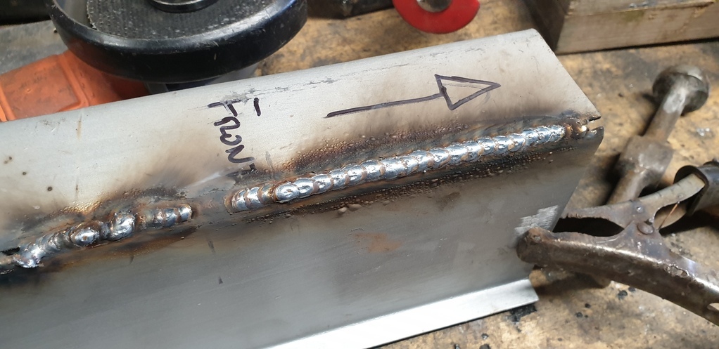
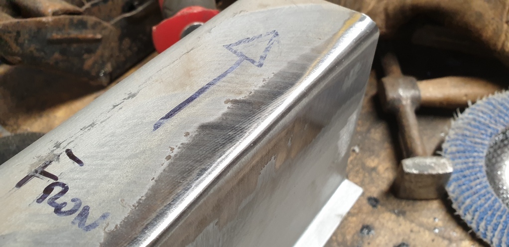
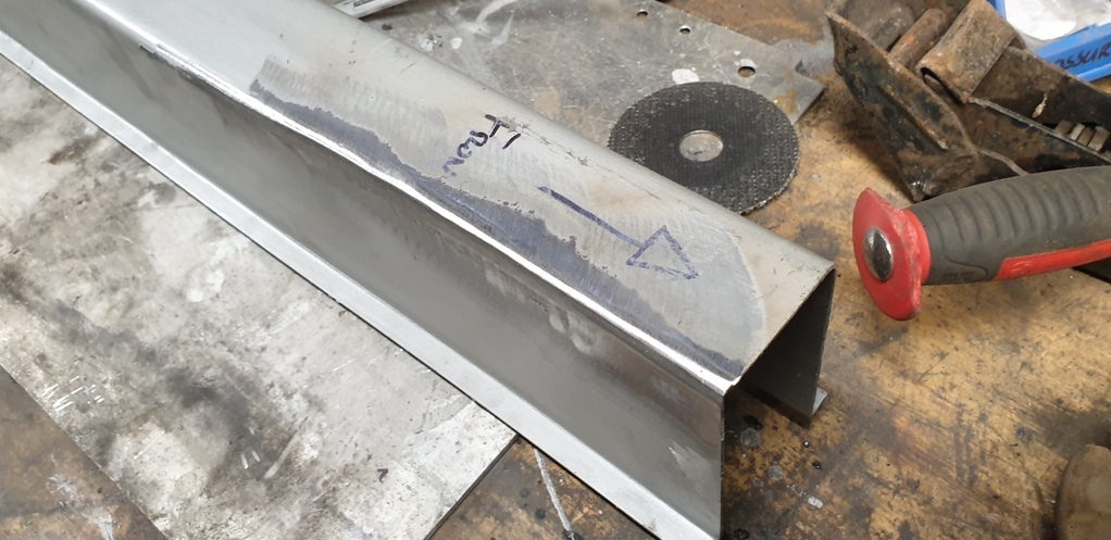
Hard to see in the picture, but it fits a lot closer now.....
Next on the ' to do ' list was fabricate the inner section to form the double chassis over the suspension and subframe area. In the last update I showed a picture of the new chassis sections all lined up together. Next to them is what looks like angle iron........ they are in fact the basis of the inner structure. Having them folded to 90 degree only......rather than folded to U section....... meant that I could trim of any access and weld the two halves together to achieve a perfect fit internally.....especially as it too would need to be narrowed at the point of where I narrowed the outer section.
Somehow I managed to loose the photos of this process.....but here's a picture of the internal section finished.....
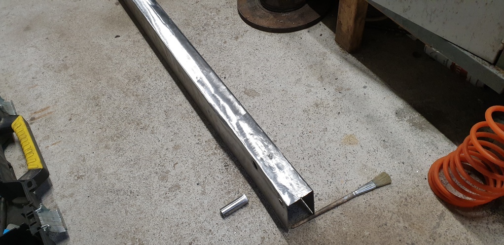
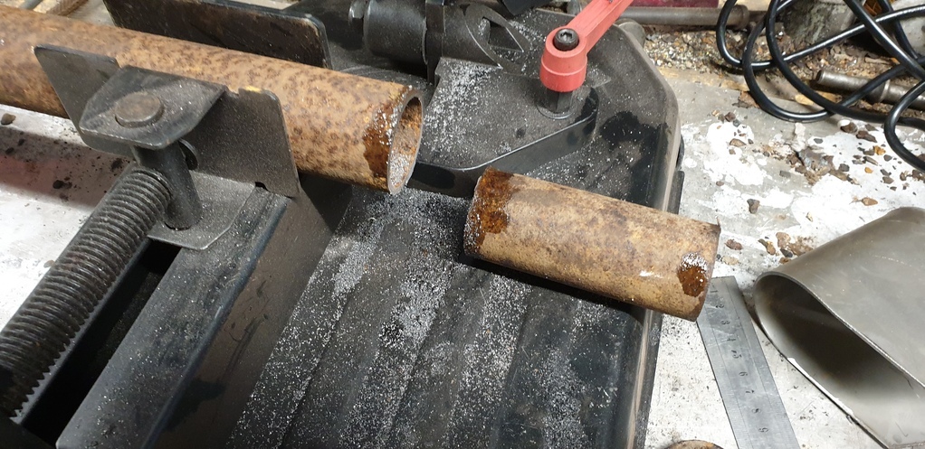
Then came the installation of the reinforcement tubes that sit inside the chassis for the steering idler mounting points. They were welded to the inner structure and holes were subsequently made at the correct location in the outer section.
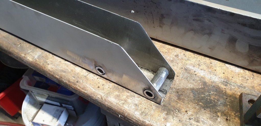
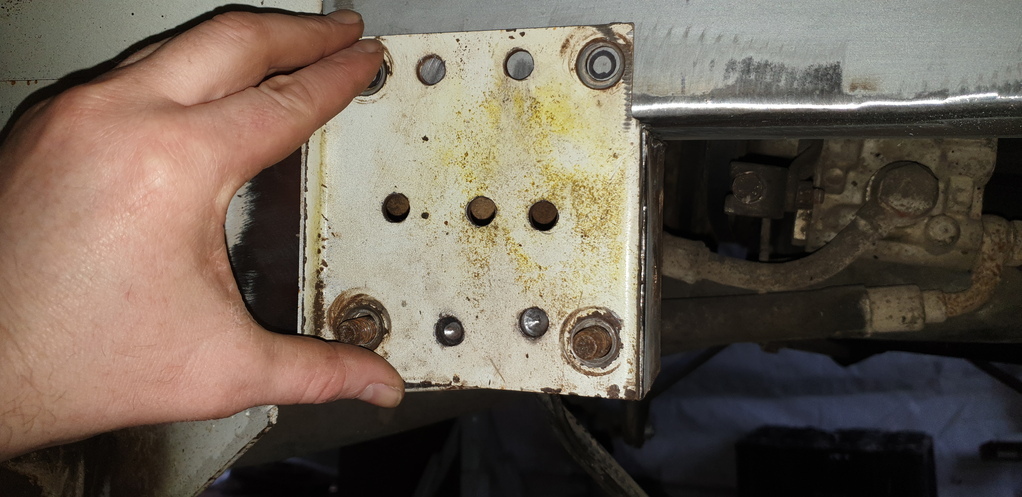
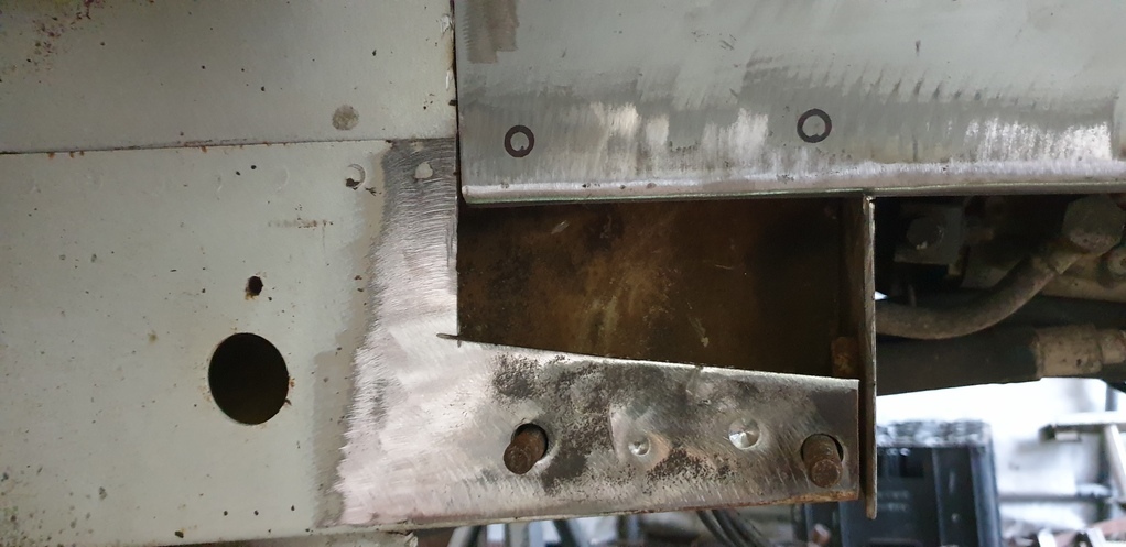
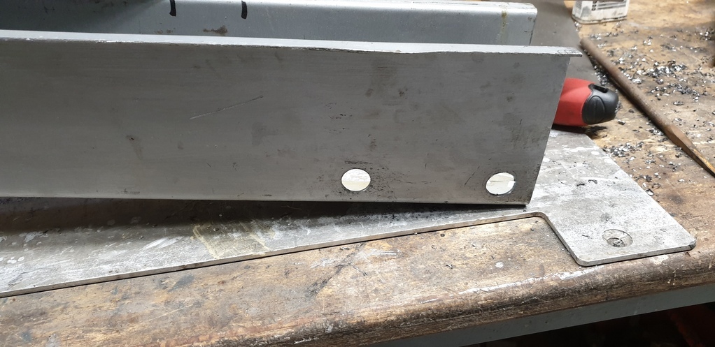
It was then time to put it to one side and concentrate on the front anti roll bar mounts.
First job.....cut what was left off of the rotten chassis and clean it up.....
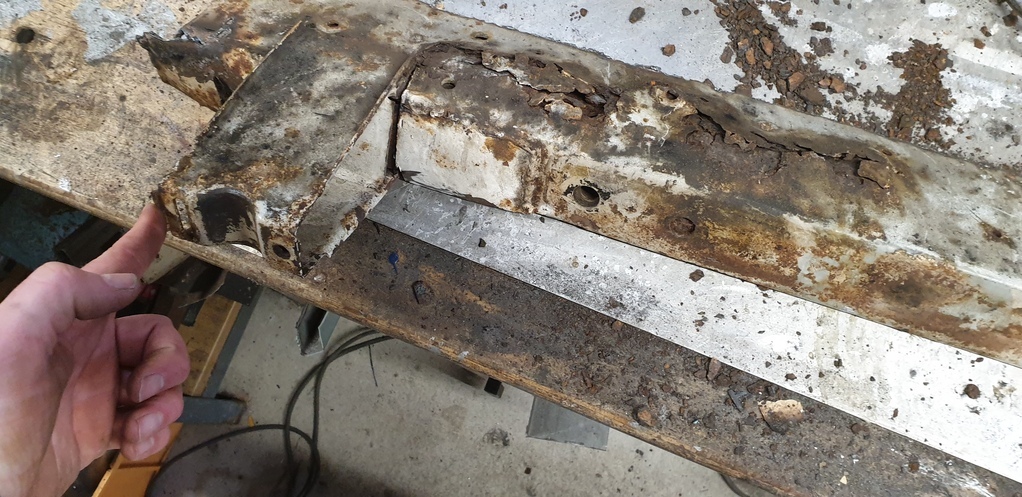
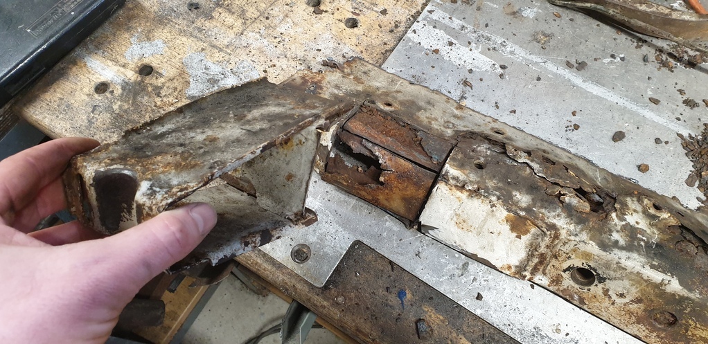
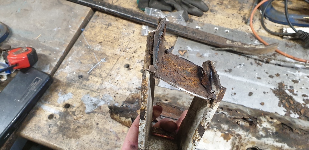
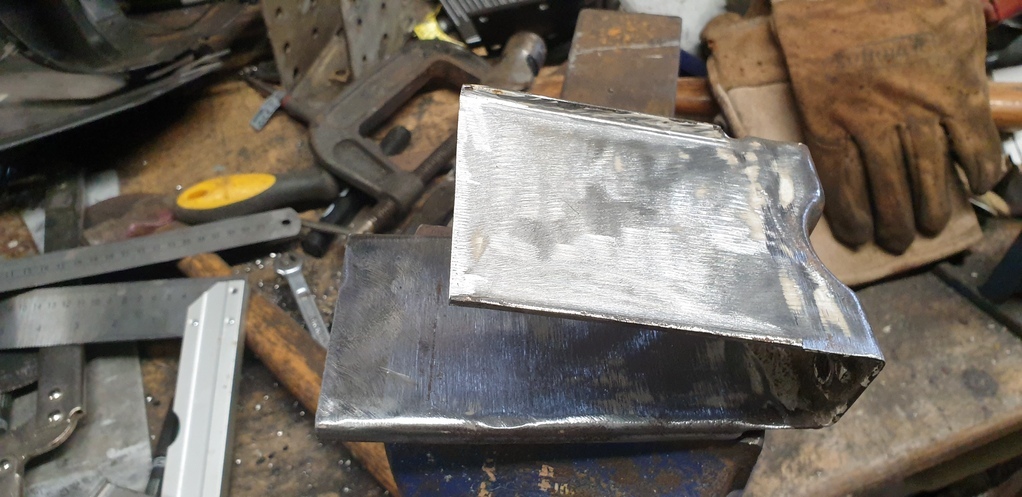
A new section was then fabricated and welded in.....
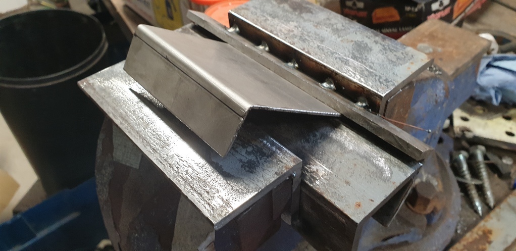
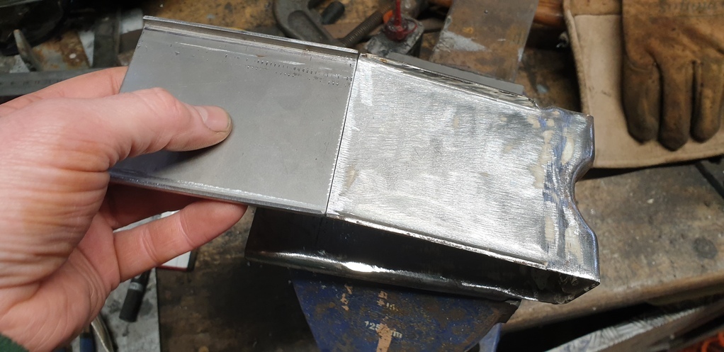
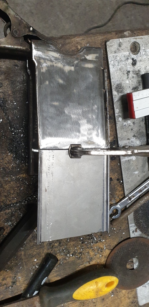
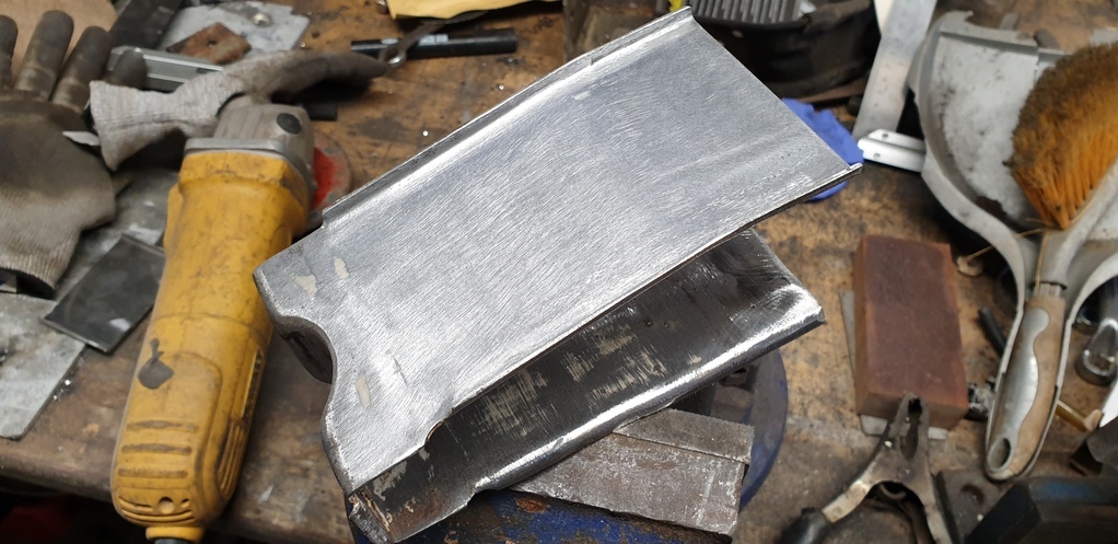
Then on to the outrigger that sits at the rear of the cab. It has the jacking point attached to it and was in really bad shape.
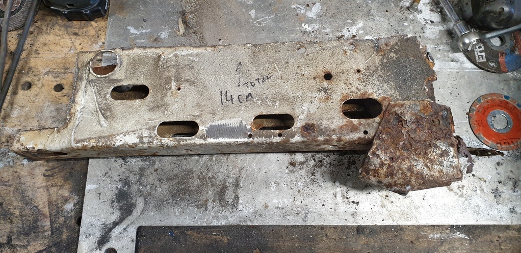
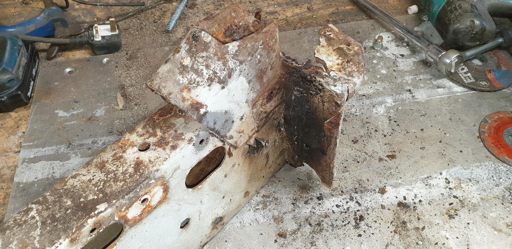
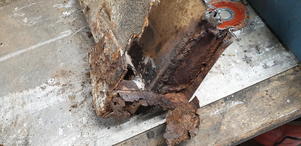
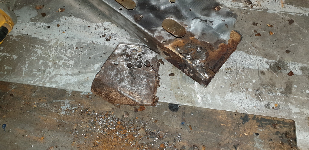
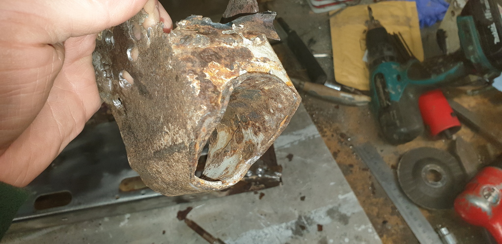
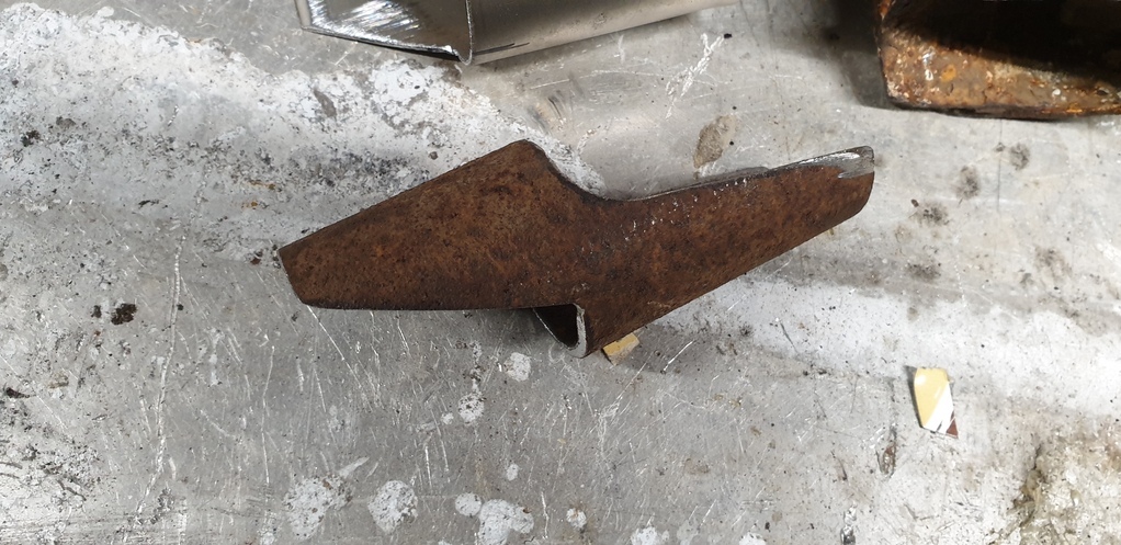
Only one thing for it......major surgery!!! First.....remove the old jacking point....
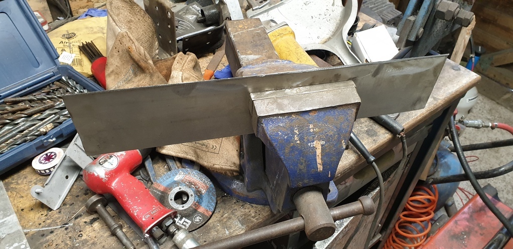
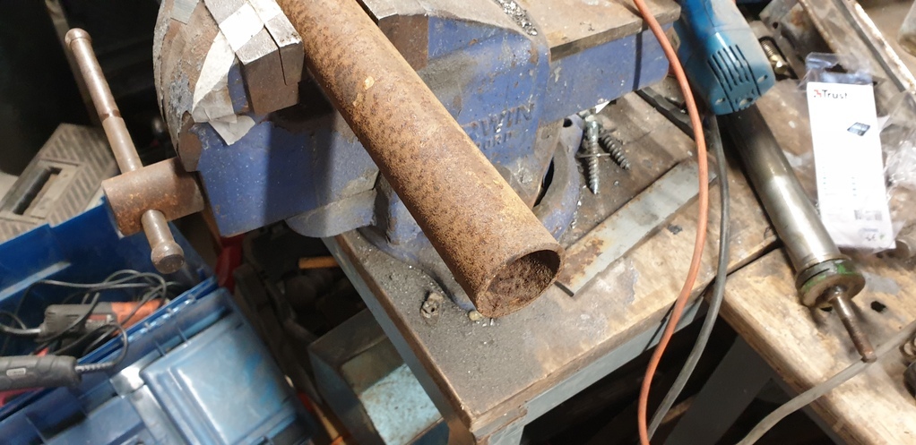
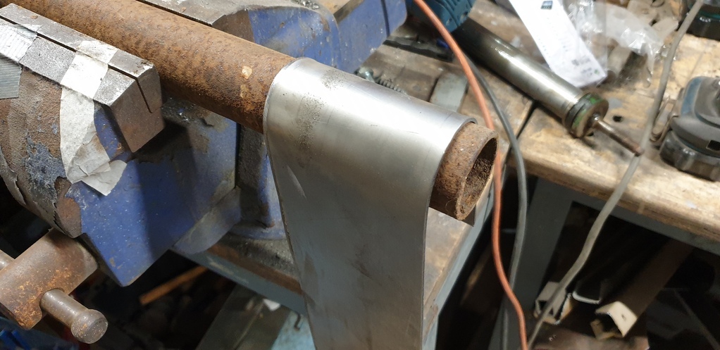
Then make a new one......
Put it through the blaster......
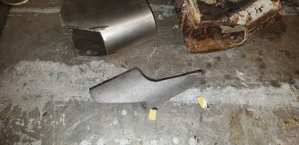
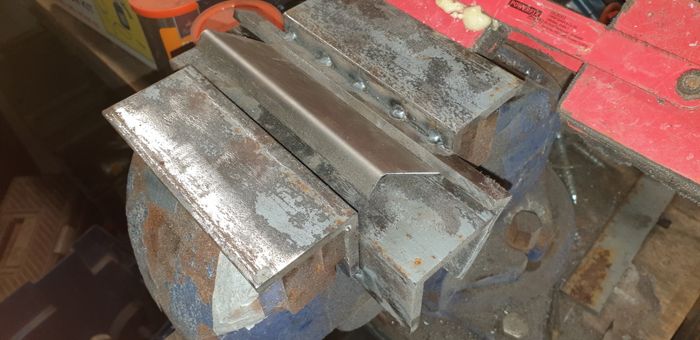
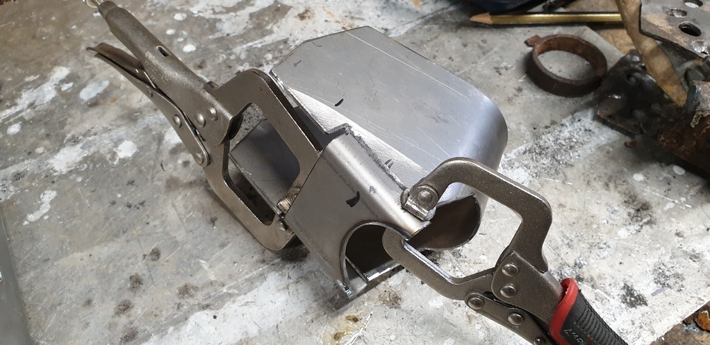
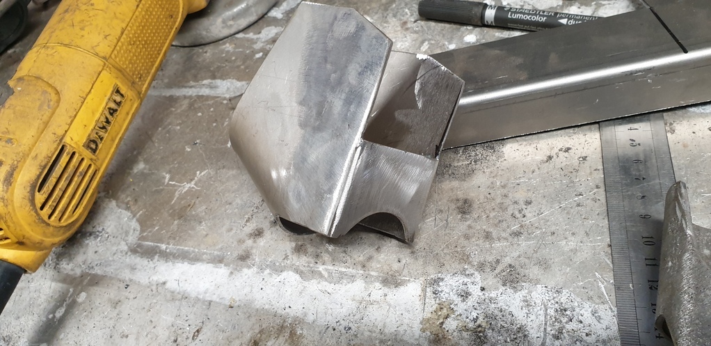
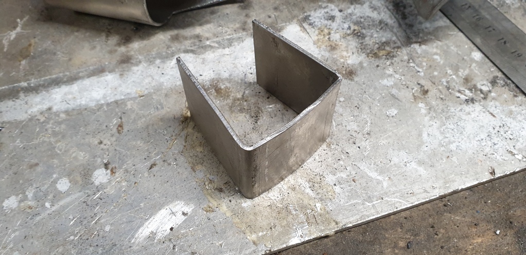
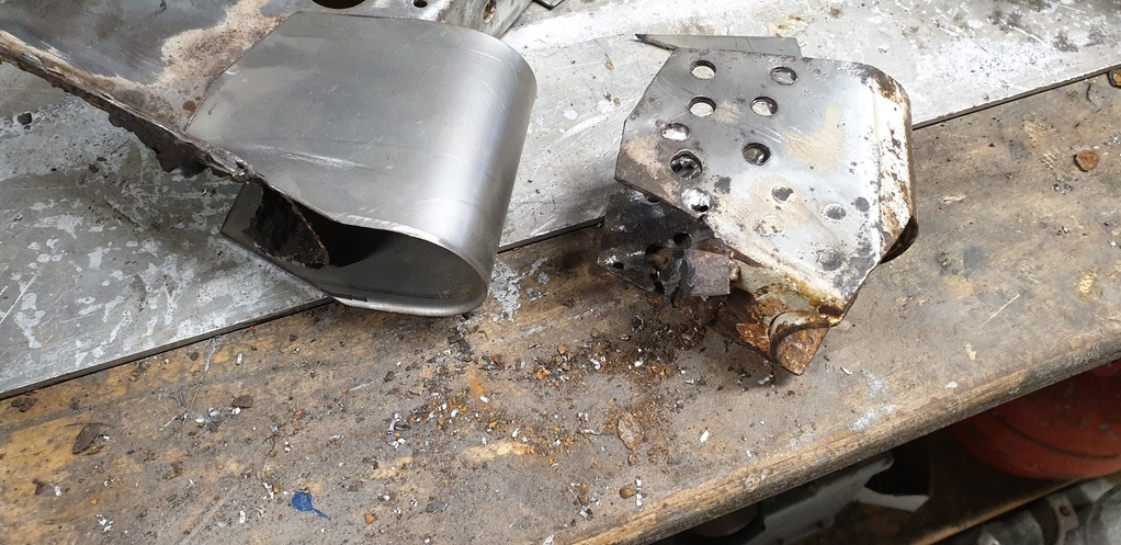
Old and new side by side.....
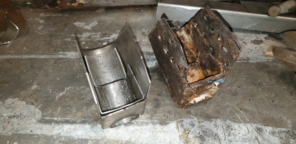
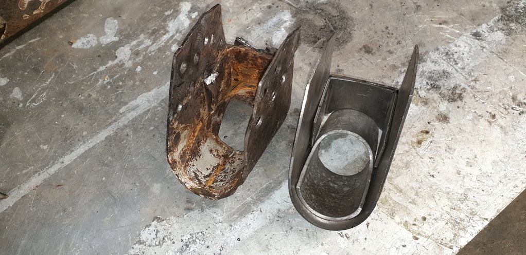
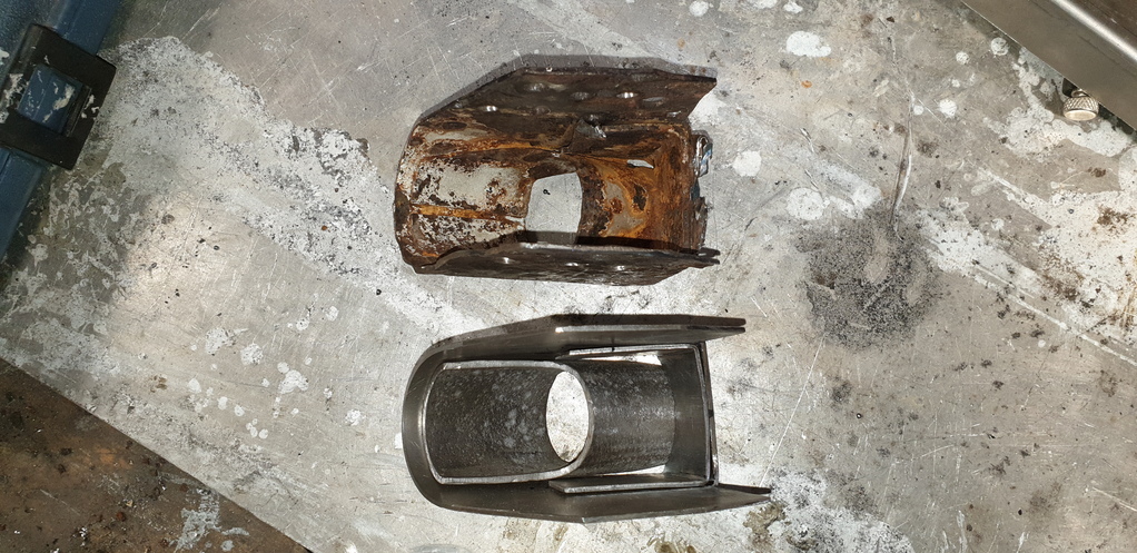
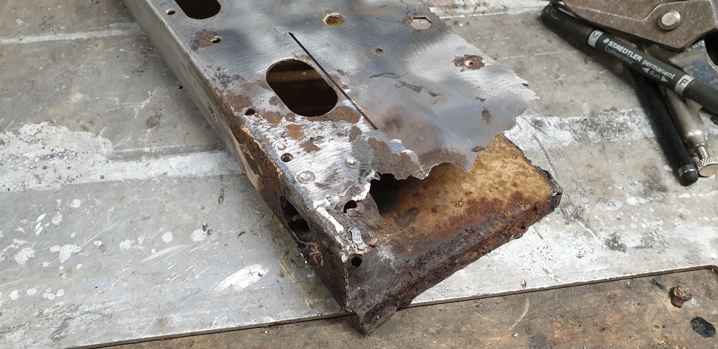
Then onto the outrigger itself....
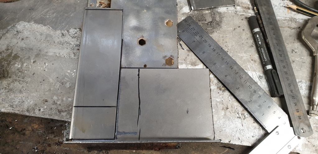
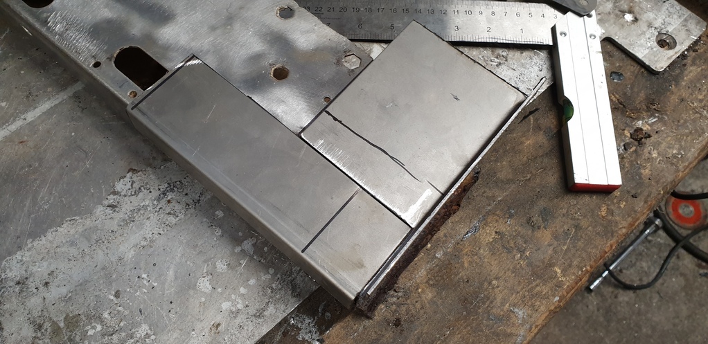
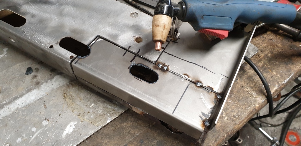
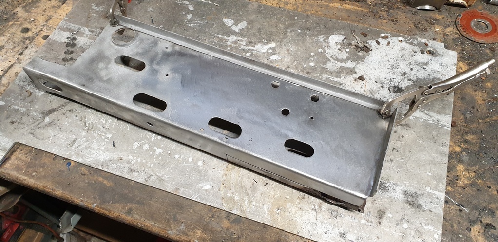
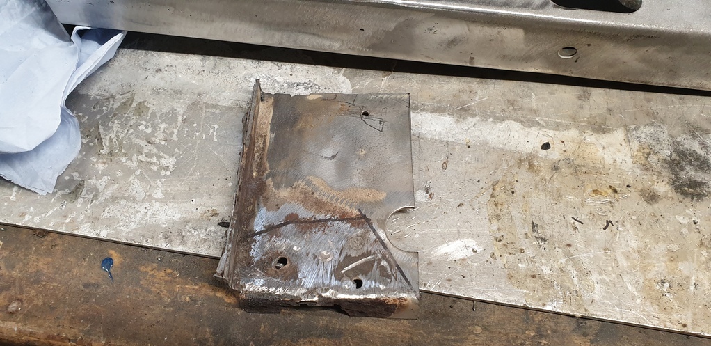
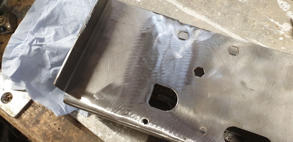
Get the chassis into position and fabricate the new mounting points....
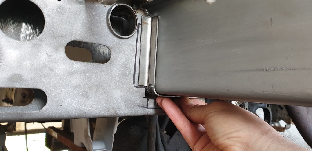
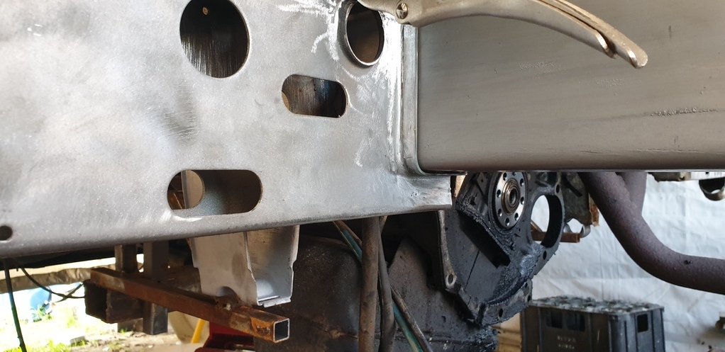
All done with the new jacking point loosely placed in position...
( I'll cut the oval hole out later )
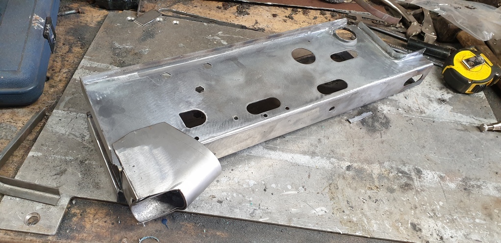
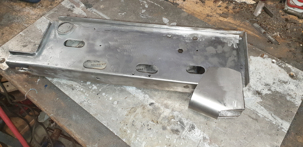
Then the fun bit of trial fitting it all up and seeing what it looks like...
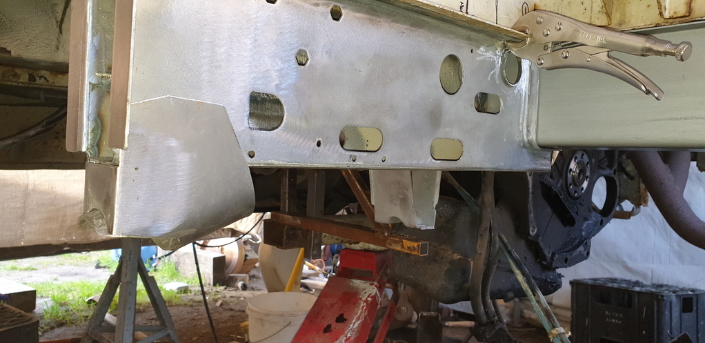
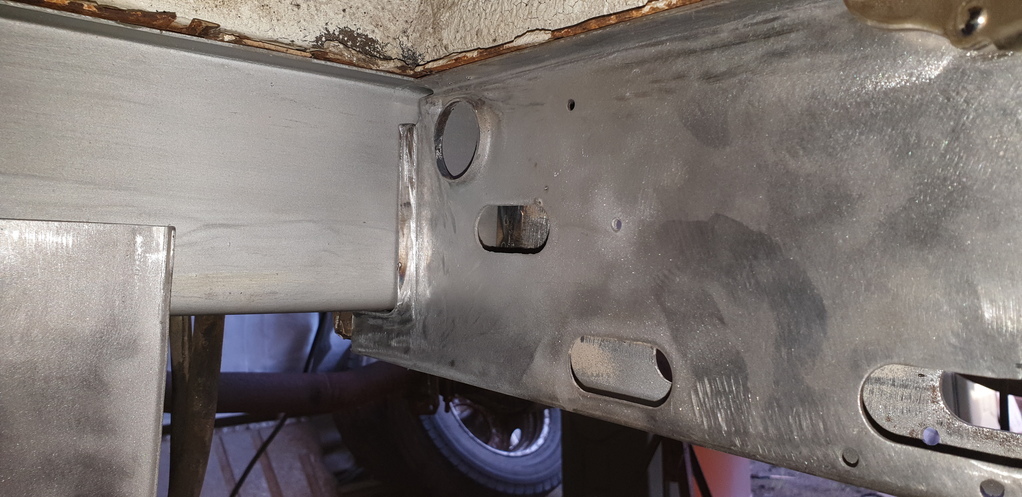
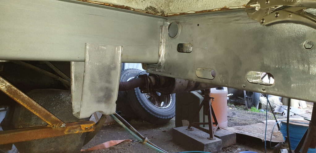
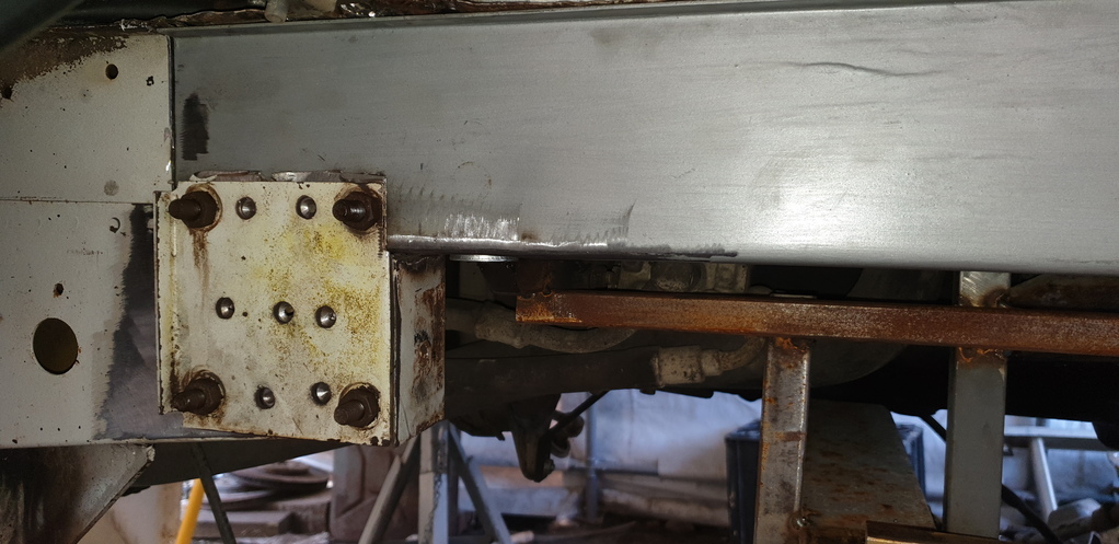
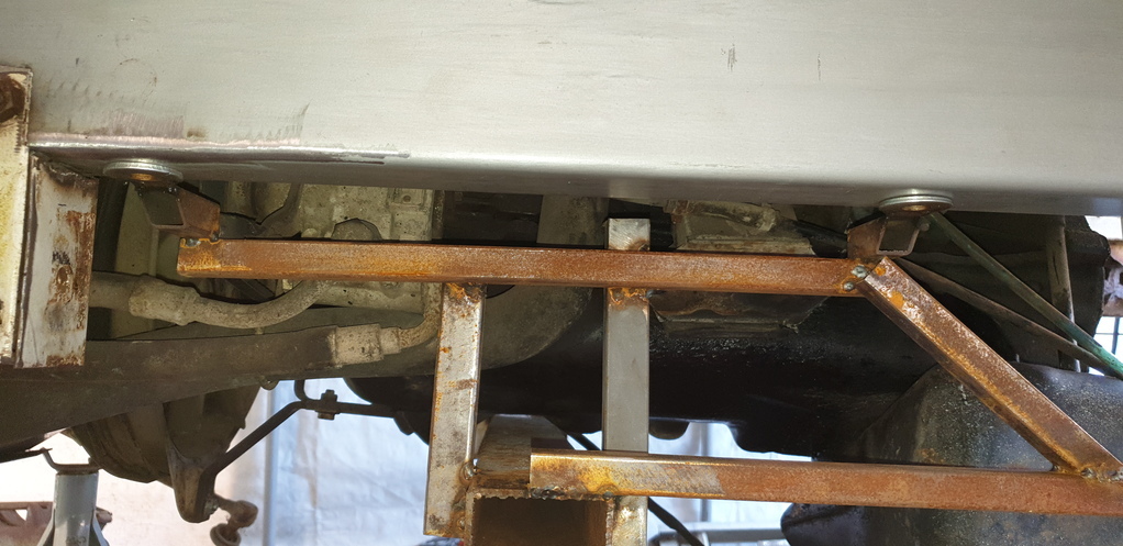
That's all for now......more soon 👍
Today's update will show the work I carried out back in March/April according to the date stamp on the photos.
After tidying up and unpicking/drilling out what seemed like a million spot welds from the remnants of the old chassis section....it was time offer up the new section for the first time.
First impressions were good......


Now.....the width of the old chassis was 60 mm. When I picked up the new chassis sections from the company that was able to fold them, they did stress that the finished items were very slightly over. Apparently, the measurements I required were right on the minimum width of what their machine was able to fold at that thickness and depth. They mentioned a figure or 2 mm over, but once I got them home and measured them myself, they were a 4 mm maximum and 2 mm minimum out. Of course, that's only 2 mm max out each side of the when the lower is centered to the upper. But.....right at the front, the chassis is sat between a load of metal work for the steering idlers and the radius rod mounts......circled in the picture below.....

This means that it has to be the correct size at that point. So a decision was made to adjust the new 'slightly' oversized chassis sections at that point only. Then have the discrepancie along the outer side leaving the inner measurement between left and right chassis sections the same as it originally was. Meaning that I'd have to make adjustments to all of the outer outriggers/hardware by reducing them at most 4 mm at the point of where they meet the chassis.......I hope that all makes sense.....because I've just given myself a headache! 😖😃
Adjustment to the new section made.....


Hard to see in the picture, but it fits a lot closer now.....

Next on the ' to do ' list was fabricate the inner section to form the double chassis over the suspension and subframe area. In the last update I showed a picture of the new chassis sections all lined up together. Next to them is what looks like angle iron........ they are in fact the basis of the inner structure. Having them folded to 90 degree only......rather than folded to U section....... meant that I could trim of any access and weld the two halves together to achieve a perfect fit internally.....especially as it too would need to be narrowed at the point of where I narrowed the outer section.
Somehow I managed to loose the photos of this process.....but here's a picture of the internal section finished.....

Then came the installation of the reinforcement tubes that sit inside the chassis for the steering idler mounting points. They were welded to the inner structure and holes were subsequently made at the correct location in the outer section.


It was then time to put it to one side and concentrate on the front anti roll bar mounts.
First job.....cut what was left off of the rotten chassis and clean it up.....


A new section was then fabricated and welded in.....


Then on to the outrigger that sits at the rear of the cab. It has the jacking point attached to it and was in really bad shape.


Only one thing for it......major surgery!!! First.....remove the old jacking point....


Then make a new one......


Put it through the blaster......


Old and new side by side.....


Then onto the outrigger itself....


Get the chassis into position and fabricate the new mounting points....


All done with the new jacking point loosely placed in position...
( I'll cut the oval hole out later )


Then the fun bit of trial fitting it all up and seeing what it looks like...


That's all for now......more soon 👍


