|
|
|
Jun 10, 2020 17:09:31 GMT
|
|
Reminds me of a guy I used to work with who had a ferrari gt4, all the wires were purple and tagged with numbered rings, unfortunately the rubber rings rotted and all fell off.....
When I've made looms I make a list of all the colours, gauge and approximate lengths I need then just order the whole lot from vehicle wiring products. Costs more but you are getting proper automotive cable and it's far easier to diagnose or splice into at a later date.
|
| |
Last Edit: Jun 10, 2020 17:59:15 GMT by kevins
|
|
|
|
Phil H
Posted a lot
  
Posts: 1,448
Club RR Member Number: 133
|
|
Jun 10, 2020 17:35:09 GMT
|
|
Don’t use rubber 😉
Might be feasible to use individual coloured cables - you won’t really know until you’ve sketched it out.
|
| |
|
|
thomfr
Part of things
  Trying to assemble the Duett again..
Posts: 694
|
|
Jun 10, 2020 18:20:47 GMT
|
Nice job! I bought a Dymo Rhino 4200 labelprinter for € 60.-which can print crimping labels for cables. Love it! Thom 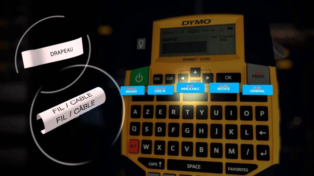 |
| |
73' Alfa Giulia Super
64' Volvo Duett
65' Volvo Duett
67' Volvo Amazon 123GT
09' Ford Focus 1.8
20' VW ID4
71' Benelli Motorella
65' Cyrus Speciaal
The difference between men and boys is the price of their toys
|
|
jonomisfit
Club Retro Rides Member
Posts: 1,790
Club RR Member Number: 49
Member is Online
|
|
Jun 10, 2020 19:55:46 GMT
|
Thanks. My wife has brother and dymo label makers so i'd already checked them out and ordered the labelling colour I want. Loom will have protective braidclosed with heat shrink, then yellow cable marker / lables under clear heat shrink. like so.  Probably over the top, but it'll keep me happy. Wirring diagrams are progressing. 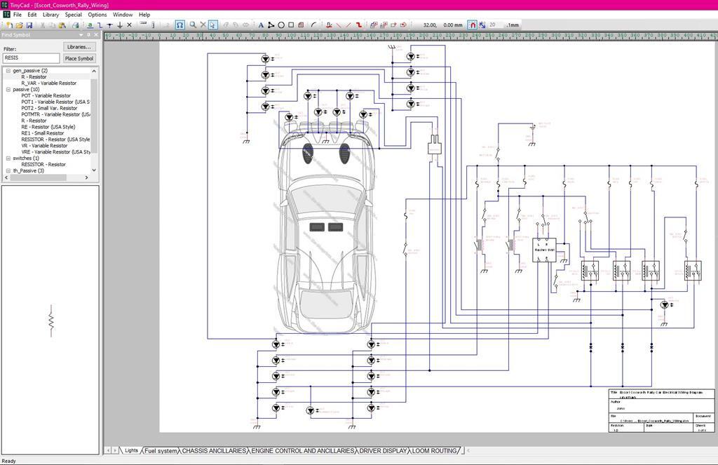 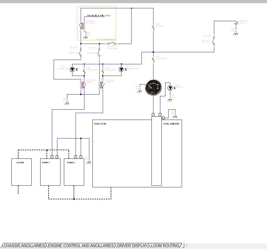 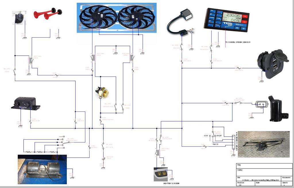 and starting to get a sense of how the loom will run round the car 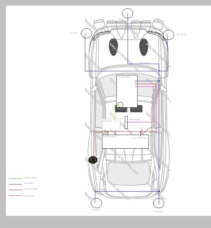 |
| |
|
|
jonomisfit
Club Retro Rides Member
Posts: 1,790
Club RR Member Number: 49
Member is Online
|
|
Jun 12, 2020 20:23:59 GMT
|
I hope people like pictures of wires, as thats pretty much all there's mainly going to be for a while I think. Granada cosworth Engine / ECU loom (worth noting the car loom for the granada has about 2x the amount of wires already laid out)  P1030825 P1030825 by jono_misfit, on Flickr started sorting through it identifying whats what, whats needed, and whats not.  P1030826 P1030826 by jono_misfit, on Flickr i needed to remove some of the wirring from the bulkhead grommet, to do this I need to get connectors through a space thats too small for the bodies, so need to remove the pins. I mean. this bit of loom isnt going to be used, so I could just cut the connectors off..... connector  P1030827 P1030827 by jono_misfit, on Flickr after much examining determined there's latches on the connector pin. needs a removal tool. insert and a light push.  P1030828 P1030828 by jono_misfit, on Flickr maybe not exactly the correct tool, but functionally equivalent.  P1030829 P1030829 by jono_misfit, on Flickr a light pull and the pin comes out  P1030830 P1030830 by jono_misfit, on Flickr and conenctor off  P1030831 P1030831 by jono_misfit, on Flickr mark down which colour goes into which terminal.... another type of connector  P1030832 P1030832 by jono_misfit, on Flickr slide out the rubber seal  P1030833 P1030833 by jono_misfit, on Flickr apply the release tool  P1030834 P1030834 by jono_misfit, on Flickr terminals pop out  P1030835 P1030835 by jono_misfit, on Flickr slowly getting less wires  P1030836 P1030836 by jono_misfit, on Flickr helpfully the ABS loom is entirely seperate from the ECU loom. At least I couldnt find any interconnects. So i have removed in its entirety. There was no way to get the ECU loom through the bulkhead grommet, and the grommet is about 20mm diam too big to fit the escort bulkhead. I'll machine up some nylon and make a split bush to replace it I think. The escorts one has been cut / torn previously and is hanging together with tape. getting much more manageable amount of wires. I also started stripping off some of the self amalgamating tape, which is horribly sticky.  P1030837 P1030837 by jono_misfit, on Flickr now i'm down to a more sensible amount of wires I can start working out what everything is and tagging it. 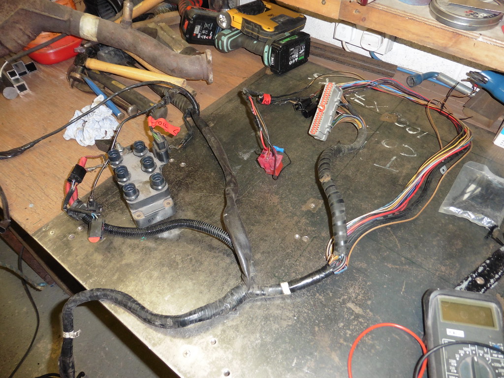 P1030838 P1030838 by jono_misfit, on Flickr slowly gettign there including using the web to identify what some of the components are (like EGR pressure sensors, vaccume control solenoids etc.)  P1030839 P1030839 by jono_misfit, on Flickr took me ages to work out what this curse word is....its the MAF  P1030840 P1030840 by jono_misfit, on Flickr There are two connectors go onto the engine, one for injectors, temp sensors, ISCV, etc. and the other for crank sensor, exhaust pressure, air temp, etc. It took ages with a a multimeter and some probles to trace it all through. I thought i was messing it up at one point as the injectors were showing as only using two pins (for six injectors) which didnt seem right. This would mean they bank fire..... I found an ECU wirring diagram on the web earlier..... the V6 is bank fired. That explains it. What interesting was how much bodging had gone on on the engine wirring. I think my favourite bits are the connector block to splice a damaged wire to the autobox full throttle kick down sensor, and the repair made to the ISCV wrirring using... connector block and 1mm ... twin and earth...... twin and freaking earth...... including the outer sheath and earth wire... Just as well i took the manifold off to trace things. I can re-wire this propperly, and also i noticed the fuel feed / return have chafed most of the way through, so I can replace them as well. Whats good is having looked over the diagram my electrical investigations and assumptions appear to be pretty much on the button. Its impressive just how much loom isnt needed to run the car. I also started stripping back insulation on the Escorts car loom so I can re-position the wires to where needed. If for nothing else it gives me a wire length template. |
| |
Last Edit: Jun 12, 2020 20:24:43 GMT by jonomisfit
|
|
|
|
|
Jun 12, 2020 20:34:32 GMT
|
|
Fantastic resto
Much respect on the wiring work
Absolute nightmare job
|
| |
Fraud owners club member
2003 W211 Mercedes E class
1989 Sierra sapphire
1998 ex bt fiesta van
|
|
jonomisfit
Club Retro Rides Member
Posts: 1,790
Club RR Member Number: 49
Member is Online
|
|
Jun 12, 2020 20:54:23 GMT
|
Thanks. I think a lot of people don't like wiring as it looks complicated and easy to get it wrong. My dad refuses to go near car wiring, anything else he'll happily do, just not wiring. If your methodical its pretty straight forward. Circuit diagrams really really help though, along with a general sense of what is likely to connect to what. That said. Being an electrician by trade (in my dim and distant past) followed by a controls system engineer (doing control systems for process plants) probably helps my confidence a bit  . |
| |
Last Edit: Jun 12, 2020 20:54:41 GMT by jonomisfit
|
|
|
|
|
|
|
Great job! I have made and modified several looms like the one on my MGB V8 conversion and adding relays and prefer to use the non sticking tape for wiring looms. I have also used heat schrink but it is more difficult to make a neat loom at juncions. You are well prepared with making the schemes but if you forget a wire, heat schrink is less forgiving then the tape. I also made a wiring loom for my Ducati motorbike and i bought a special tool to release the pins and a specific plier for those pins and was able to source the brand of connectors used on the Ducati and was able to buy new pins and housings because i needed some larger housings due to to the extra wires for the relays. It was not a cheap routing but gives a trouble free electrical system. With those screw drivers, you may damage the fragile retaining pins. A loom with this tape looks very neat especially when there are a lot of junctions like in my situation with the many added relays 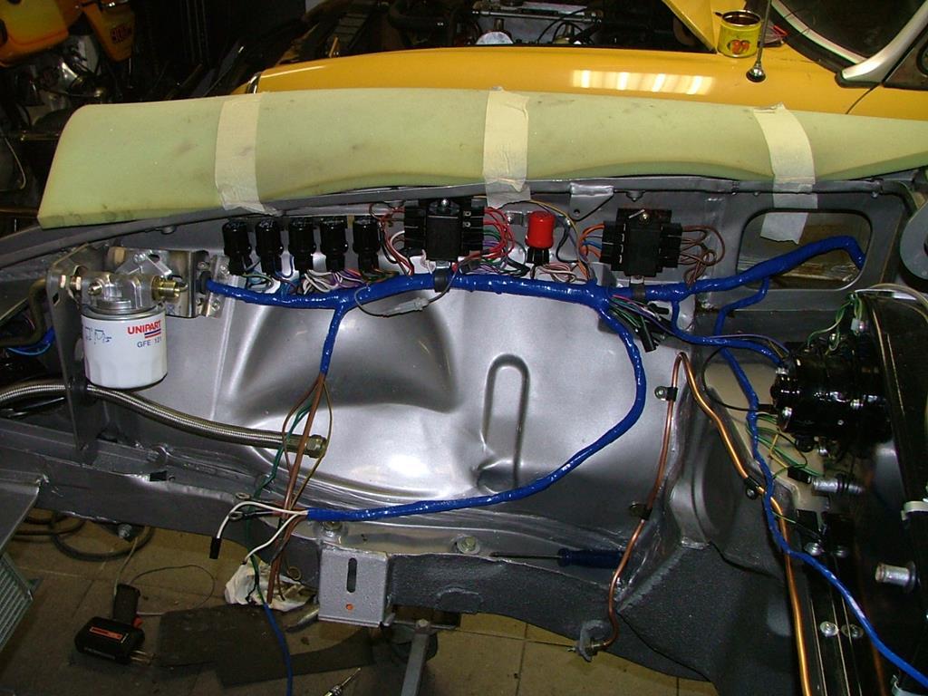 Keep up the good work as it is an enjoyable thread! Peter |
| |
|
|
jonomisfit
Club Retro Rides Member
Posts: 1,790
Club RR Member Number: 49
Member is Online
|
|
|
|
|
Thanks.
I'm going to be using expandable braided sleeving in the car with heat shrink on joints, connectors, and branches. Which nicely protects, but with care can be opened for changes.
In the engine bay I've found some impermeable heat resistant sleeving so will likely use that, again with heat shrink.
With the state the engine bay wiring has gotten into it's clear careful routing and protection is needed.
I'm definitely going to be getting the right tools for pin fit / extraction and crimping pins.
I may as well do it once and right.
Plus I'll then have the kit for future projects. Most notably the morris and toddler_misfits totrod when it gets started.
|
| |
|
|
mk2cossie
Club Retro Rides Member
Posts: 3,062  Club RR Member Number: 77
|
|
|
|
Very nice progress indeed  Are you planning on using the Ford EEC IV and the car on the road? If so, don't remove the EGR gubbins, as the BOA runs about 18:1 AFR without the EGR connected and on constant throttle! I know this from many miles in mine with the AEM wideband and gauge  |
| |
|
|
jonomisfit
Club Retro Rides Member
Posts: 1,790
Club RR Member Number: 49
Member is Online
|
|
|
|
|
Thanks!
For speed I was hoping to get it running using the base ECU and was going to junk it all the EGR stuff as figured it's superfluous.
I shall ensure I don't!
Either that or I'll need to bump phase 2 plans for a stand alone ECU.
|
| |
|
|
v8ian
Posted a lot
  
Posts: 3,832
|
|
|
|
|
I used a similar labelling technique for wiring up my cortina 15 years or so ago, but dymo printers were not readily available then, clear heat shrink, made the labels using a lap top and a printer, type everything you want, select the font and size you want, print, cut with scissors and attach to loom using heat shrink,
|
| |
Atmo V8 Power . No slicks , No gas + No bits missing . Doing it in style.
Austin A35van, very different------- but still doing it in style, going to be a funmoble
|
|
v8ian
Posted a lot
  
Posts: 3,832
|
|
Jun 13, 2020 13:27:44 GMT
|
|
I ,
|
| |
Last Edit: Jun 13, 2020 13:29:16 GMT by v8ian
Atmo V8 Power . No slicks , No gas + No bits missing . Doing it in style.
Austin A35van, very different------- but still doing it in style, going to be a funmoble
|
|
teaboy
Posted a lot
   Make tea, not war.
Posts: 2,125
|
|
Jun 13, 2020 21:11:33 GMT
|
|
What is an ISCV?
I Googled it and it’s either IntelliSpace Cardiovascular or Guatemalan road tax...
|
| |
|
|
Darkspeed
Club Retro Rides Member
Posts: 4,882
Club RR Member Number: 39
|
|
Jun 13, 2020 21:36:22 GMT
|
What is an ISCV? I Googled it and it’s either IntelliSpace Cardiovascular or Guatemalan road tax... At a guess Idle Speed Control Valve fits |
| |
|
|
jonomisfit
Club Retro Rides Member
Posts: 1,790
Club RR Member Number: 49
Member is Online
|
|
Jun 13, 2020 21:40:53 GMT
|
|
Darkspeed is right.
Idle speed control valve. The route to all sorts of random stalling if its not sorted correctly.
|
| |
|
|
jonomisfit
Club Retro Rides Member
Posts: 1,790
Club RR Member Number: 49
Member is Online
|
|
Jun 14, 2020 19:15:30 GMT
|
More wires today. stripped off the loom binding from the escort car loom, which took ages.  P1030841 P1030841 by jono_misfit, on Flickr it revealed a number of unidentified random wires that had been cut off.  P1030842 P1030842 by jono_misfit, on Flickr Some went back to the fuse panel connector, some were orphaned in the loom.  P1030843 P1030843 by jono_misfit, on Flickr pulled back through the loom where they still enter the connector until I can work out they are.  P1030844 P1030844 by jono_misfit, on Flickr  P1030845 P1030845 by jono_misfit, on Flickr not sure why, but the main fuel pump earth ran from an earth point near the fuse panel the length of the car to the fuel pump, rather than pick up near the pump. I'm guessing so a signficant earth is povided the whole length of the loom should there be a fault / it get cut in an accident.  P1030846 P1030846 by jono_misfit, on Flickr pulled back everything then started a temorary fit in the car. Using sticky cable clips. These work nicely as a temporary fitting but need to be screwed or rivetted on for anything longer term as they always fall off in time if just teh sticky pad is used!  P1030847 P1030847 by jono_misfit, on Flickr laying out the loom  P1030848 P1030848 by jono_misfit, on Flickr  P1030849 P1030849 by jono_misfit, on Flickr ran the fuel sender and fuel pump feed to the new locations.  P1030850 P1030850 by jono_misfit, on Flickr I also changed the main loom routing to the centre tunnel which means I can re-use this loom section into my new arrangement as its shortened the loop and wont need extending.  P1030851 P1030851 by jono_misfit, on Flickr I also found a range of other centre console switches that had been cut off and pulled them back. A fair collection of no longer needed cabling 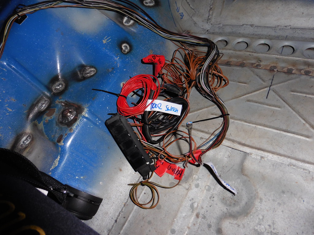 P1030852 P1030852 by jono_misfit, on Flickr Then started on the main engine bay loom  P1030853 P1030853 by jono_misfit, on Flickr de-binding the ABS loom  P1030854 P1030854 by jono_misfit, on Flickr more de-binding  P1030855 P1030855 by jono_misfit, on Flickr continued de-dinbing the rest of the loom.  P1030857 P1030857 by jono_misfit, on Flickr Came across many bits like this. No idea what was there, but all cut back and hidden in the loom.  P1030856 P1030856 by jono_misfit, on Flickr The loom has been pretty butchered about. start pulling back all the ABS loom bits. Where I can i'm un-picking through the loom and leaving conenctors on, simply so that I've got as much useable wire for when I need it later.  P1030858 P1030858 by jono_misfit, on Flickr bits like this i really don't understand. This is a signal wire that goes from a splice into the main power feed to the ABS pump (about 100mm from the pump on the engine side of the bulkhead) and runs all the way back to the ABS module.  P1030859 P1030859 by jono_misfit, on Flickr the purple relay is the main power feed for the ABS pump. Its mounted next to the ABS module. The big red power feed you can see coming out of it (red with blue stripe is feed in, red is power out... at least in this case) is the same one that runs to the ABS pump where the little red wire is spliced onto it then runs all the way back to the ABS module. It could just loop the 100mm to the ABS module from the relay without a 6m journey down the car and back.  P1030860 P1030860 by jono_misfit, on Flickr the only thing I can surmise is, as ABS is a high integrity system, they need to be certain that the pump has a power feed and the signal wire is there near the pump to ensure that you cant really get an ABS pump power feed cable failure / cut downstream of where the signal is taken (at the bulkhead etc.). there are a number of similar feeds and signals in the ABS part of the loom. ABS loom starting to thin out a bit now.  P1030861 P1030861 by jono_misfit, on Flickr my cable stocks are mounting.  P1030862 P1030862 by jono_misfit, on Flickr The main ones for re-use are the power feeds cables. |
| |
Last Edit: Jun 14, 2020 19:18:21 GMT by jonomisfit
|
|
|
|
|
Jun 14, 2020 19:47:41 GMT
|
|
If it was originaly a UK road car they were all butchered at the factory when a 3rd party fitted immobolisers before they were shipped.
When wires rin back from a major component like the abs pump it is often because the control module monitors pump voltage as part of the diagnostics.
|
| |
|
|
jonomisfit
Club Retro Rides Member
Posts: 1,790
Club RR Member Number: 49
Member is Online
|
|
Jun 14, 2020 19:58:09 GMT
|
|
Good info. Thanks!
|
| |
|
|
jonomisfit
Club Retro Rides Member
Posts: 1,790
Club RR Member Number: 49
Member is Online
|
|
Jun 15, 2020 20:58:51 GMT
|
after a bit more tracing back I managed to expunge the ABS loom.  P1030863 P1030863 by jono_misfit, on Flickr then start tracing back all the ECU wires  P1030864 P1030864 by jono_misfit, on Flickr then eventually managed to dig that out as well  P1030865 P1030865 by jono_misfit, on Flickr I labled what I could, but about 40% of the inputs to the ECU were already cut and I had no idea what they went to! There are a lot more wires to it than on the V6 engine, i guess its to do with the turbocharging.  P1030866 P1030866 by jono_misfit, on Flickr Just got to budle it up and can then i'll have it should I ever need it. I've also been sketching out what the centre panel may look like.  Centre panel 1 Centre panel 1 by jono_misfit, on Flickr there is not a lot of room and i'm \lready thinking I may need to use some of the other dashboard spaces for some functions.  Centre panel2 Centre panel2 by jono_misfit, on Flickr |
| |
|
|




 .
. 

