Time for a little update, as I've been chipping away at this little project bit by bit. The updates aren't as frequent as I'd like, but I have very little time to spend on the project so each update is the culmination of an hour here and an afternoon there!
Anyway, we're inching closer to the union of Mercedes and Nissan oily bits. Last time, I left off having selected the concentric clutch slave for the project. I then had to somehow get it to mount to a Mercedes automatic bellhousing!
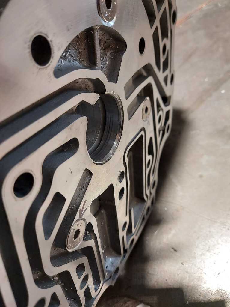
By my calculations, the slave needed to sit 30mm further towards the clutch fingers so that it will be adequately engaged. So I ordered a 6 inch disc of aluminium of the appropriate thickness and got busy on the lathe...
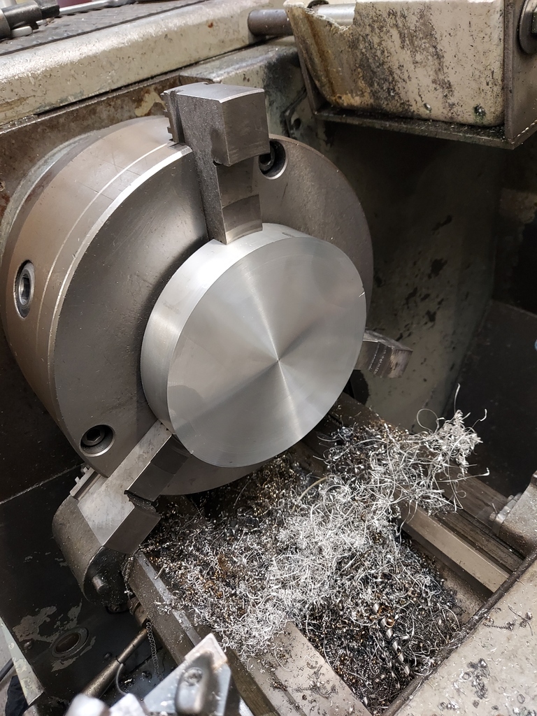
This project is the first time I've done any lathe work, so I'm learning as I go with it. I first faced up both surfaces, then reduced the diameter by a few mm so it fit nice and snug within a circular recess in the bellhousing.
I then put a hole in the centre in order for it to fit concentrically over the input shaft sleeve. I planned to adapt the centering pin, which I'd made previously to centralise the adaptor and bellhousing, to align the slave cylinder. As the cyliner internal bore is smaller than the input shaft sleeve I needed to reduce this diameter. I also machined a recess into the adaptor as the cylinder I'm using also had an built in gearbox oil seal for the original application. I don't need this, but without the recess it won't sit flush with the adaptor.
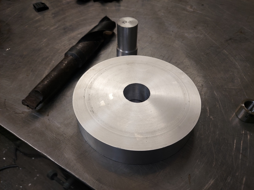
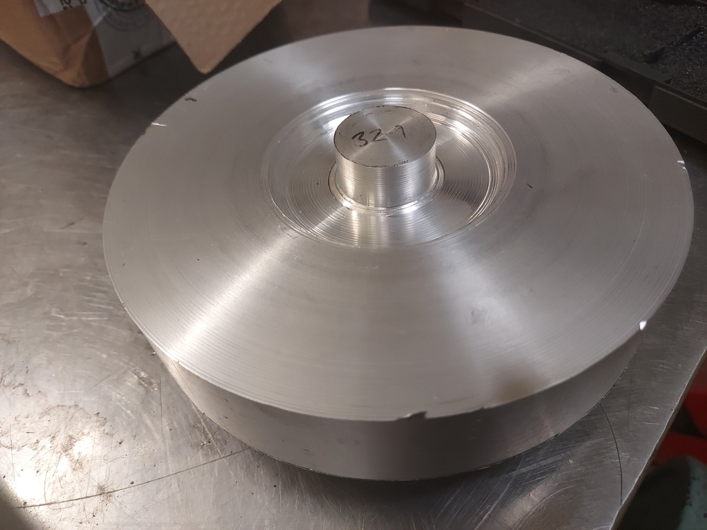
Holes in the bellhousing were repurposed to attach the slave cylinder adaptor. I countersunk them so that the fasteners fit flush.
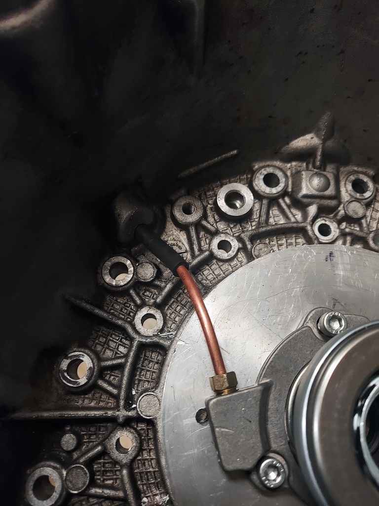
I then drilled and tapped the front of the adaptor so that the cylinder bolts to the adaptor with the pipe union pointing to 12 o'clock. This cyliner doesn't have a bleed nipple so will be fun to bleed I'm sure. I think this feature, and the oil seal arrangement, means I probably would have gone for a different cylinder in hindsight, but we're here now so I just need to make it work.
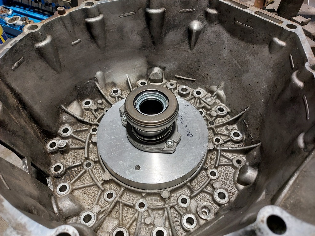
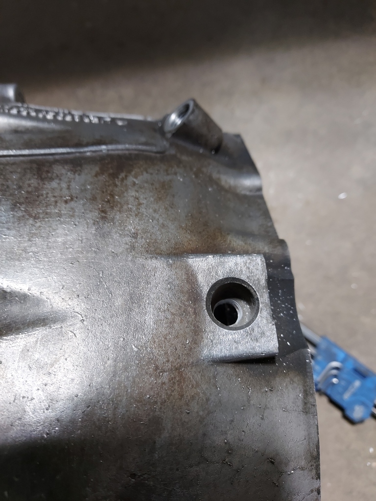
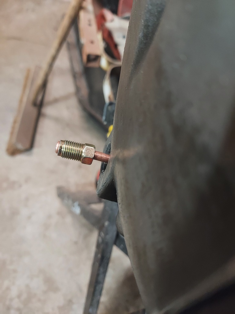
I then made up a short pipe from the cylinder to outide the bellhousing. I used a convenient blank in the casting to put a male fitting ready to take a flexi to the master cylinder when the gearbox is back in. The black pipe is a rubber sleeve I slid over the pipe to stop it chafing on the bellhousing.
So that's the clutch arrangement hopefully sorted. I'll only know for sure when it's all bolted together though!
Another machining job I needed to tackle was the spigot bearing. I'd got the engine and transmission at a distance which meant I had good spline engagement with the clutch, but this meant that the end of the input shaft sat rather far inside the flywheel (in fact, through the other end!). This meant that if I put the spigot bearing centrally in the flywheel there was a risk that a step in the input shaft would hit the bearing, and stop the gearbox and engine surfaces mating. Or at the very least It could put pressure on the input shaft and break something. I measured and measured again... it was close, it may or may not be an issue depending on how accurate my measurements were (hey, I'm no engineer!). I decided it wasn't worth the risk, and seeing as I needed to make an adaptor to fit the Nissan spigot bearing anyway, I might aswell design it so that it sits further towards the engine and avoids any issues with the input shaft step-up.
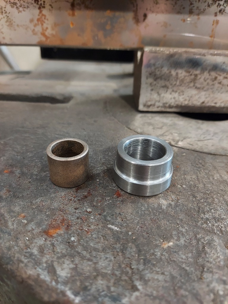
Here we have the adaptor, with the Nissan L28 spigot bearing. I designed it to be a press fit into the flywheel, and the bearing is a press fit into the steel adaptor. Full disclosure: I actually got a mate to make this piece after I gave him the dimensions. I just didn't have the time, and it needed to be super precise and I didn't want to mess it up.
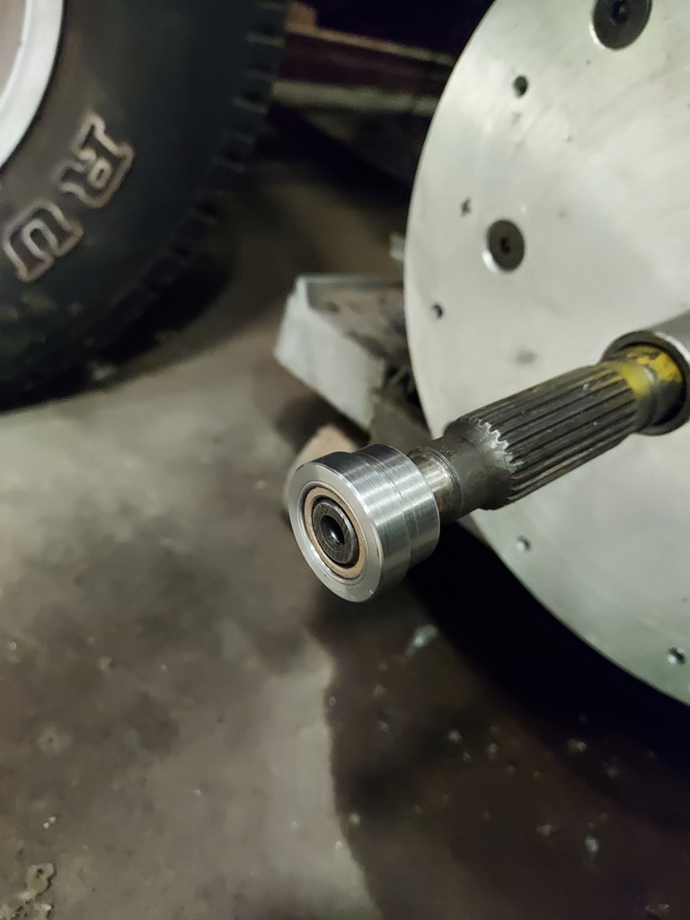
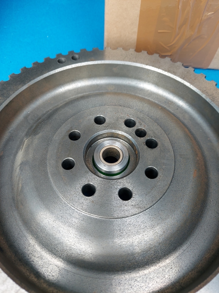
I test fitted it on the input shaft after I pressed the bearing in just to make sure it hadn't distorted, then pressed it into the back of the flywheel. You can see the step in the input shaft in the photo.
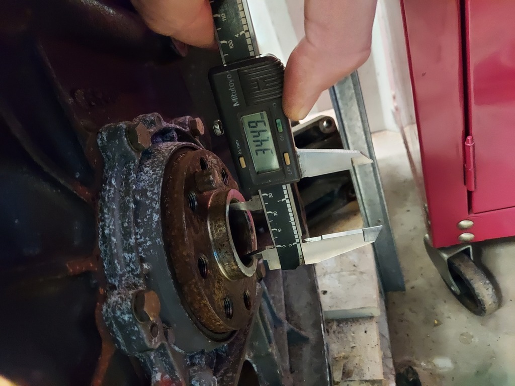
The flywheel bolts flush with the crankshaft flange, howerver there is a centre bore running quite deep into the crank flange, and my adapter is a few mm smaller in diameter. This positions the spigot bearing to run on the end of the input shaft.
So that's all the engine and gearbox adaptors made! My next step is to test it all by joining the engine and gearbox and crossing fingers and toes that all this theory actually works... You'll have to look out for a future update to see whether it's worked or not (Oh god I hope it works!!)
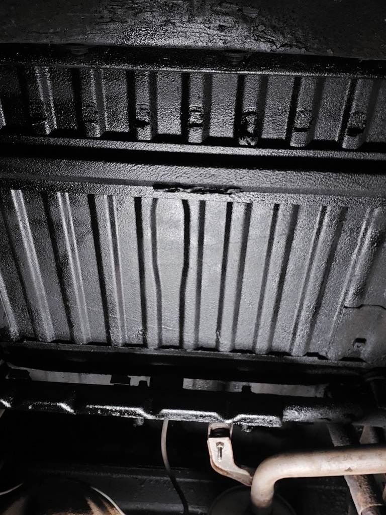
Other jobs I've done on the Patrol is undersealing the area above the fuel tank. It wasn't particularly bad, but I wanted to throw something on there while I had the opportunity. It was a messy old job but worth doing to keep any rust at bay.
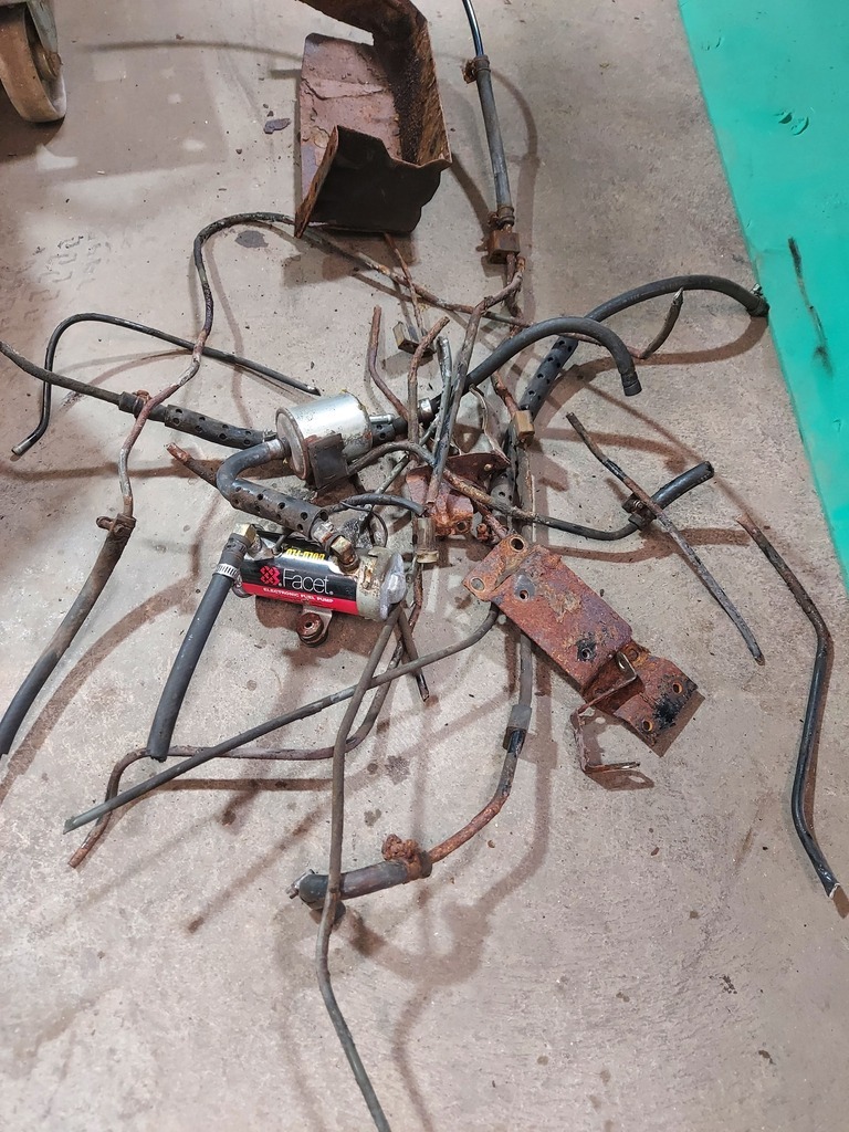
I also removed all of the old fuel lines and the fuel pump. The lines were in terrible condition and I think one more year of use would have given me multiple fuel leaks. This was a pretty horrendous job! Lots of rusted fasteners, upside-down angle grinding, grit and rust in the eyes... you know how it is. Had to be done though! Braided fuel lines will be going in before the gearbox gets bolted in.
So that's us pretty much up to date. I've gone into quite a lot of detail with all the adaptors and machining, I hope it's not too dry to read through! I figured it might help someone else who is contemplating doing a conversion where no adaptors exist. This project is a bit of a slow burner, I only get a few hours to work on it each week so progress is slow and steady! Retro Rides Gathering gave me a boost of inspiration though, I really REALLY want to finish it in time for RRG22... not that I want the pressure of a deadline...


 and an apparent failure to disengage..... Guess how I know this