jonomisfit
Club Retro Rides Member
Posts: 1,789
Club RR Member Number: 49
|
|
Jul 16, 2017 20:11:34 GMT
|
Little progress today. I've still not got the bits I need for the bead roller, and am stuck on that at present till I do. I got a reversing switch for the lathe and tried to wire that up today. After about 2 hrs of effort I still havent got it running and have realised I need to buy a few things to get that finished, so thats stuck half done. I was fairly frustrated by this point so quickly put the pedal box together so I could mock up a position. Roughly in situ 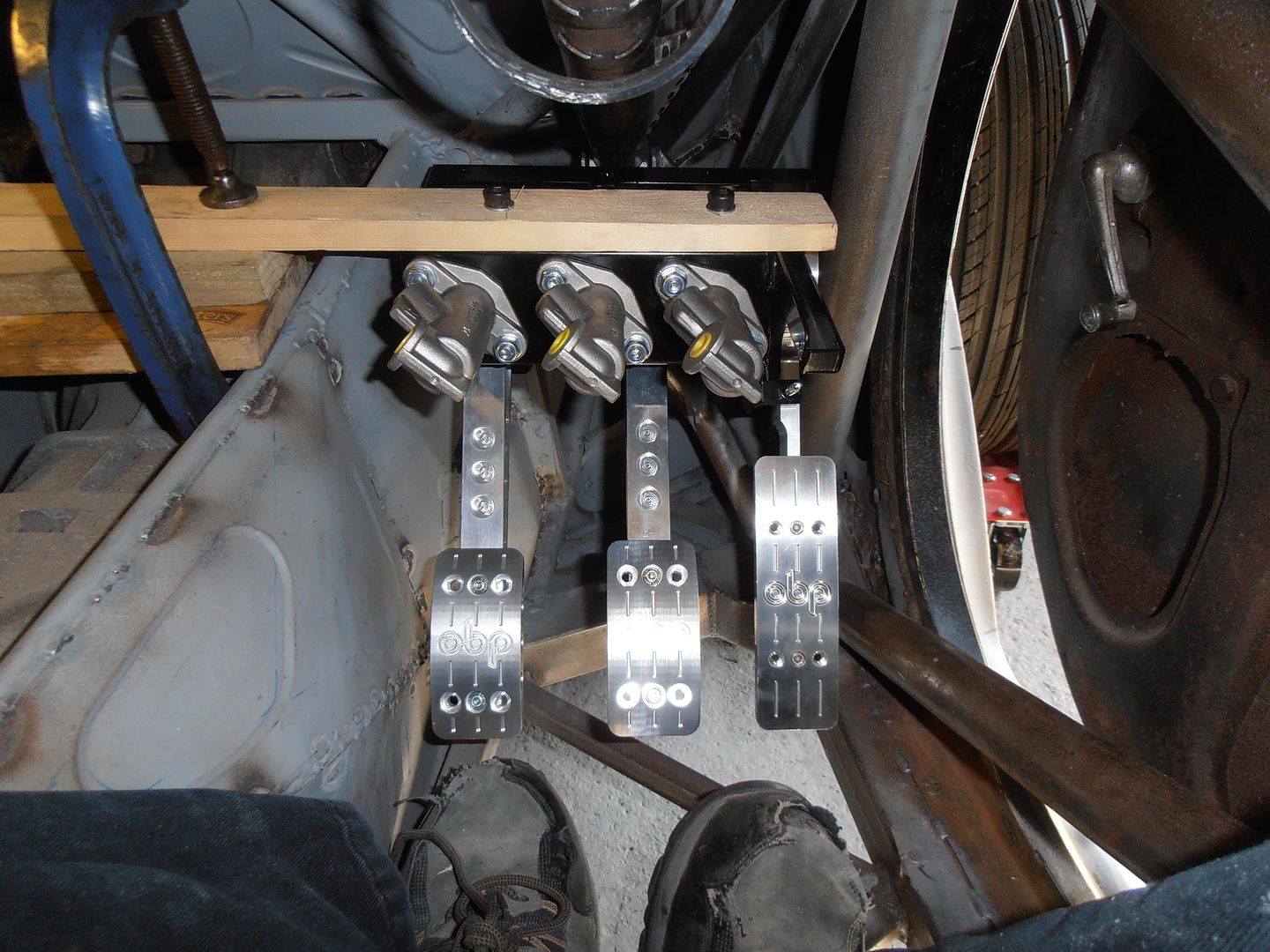 Can actuate all the pedals ok in this position 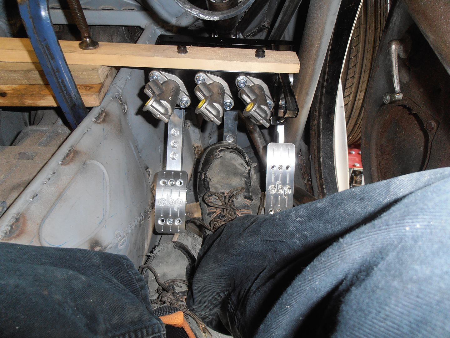 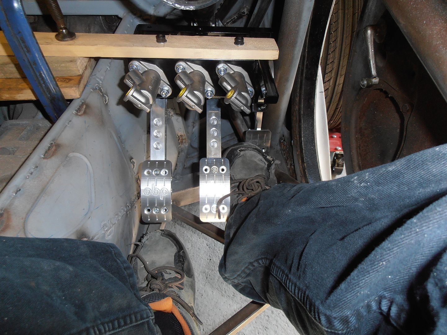 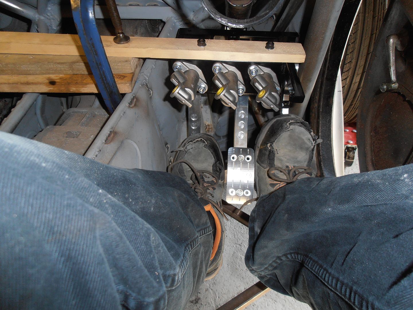 And with the wheel in situ there's loads of knee / space to tidy it all up for the SVA man. 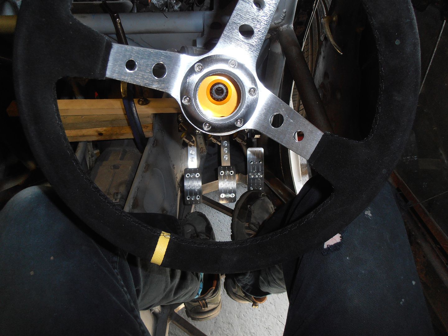 The mounting arrangement will get updated before finishing :-) 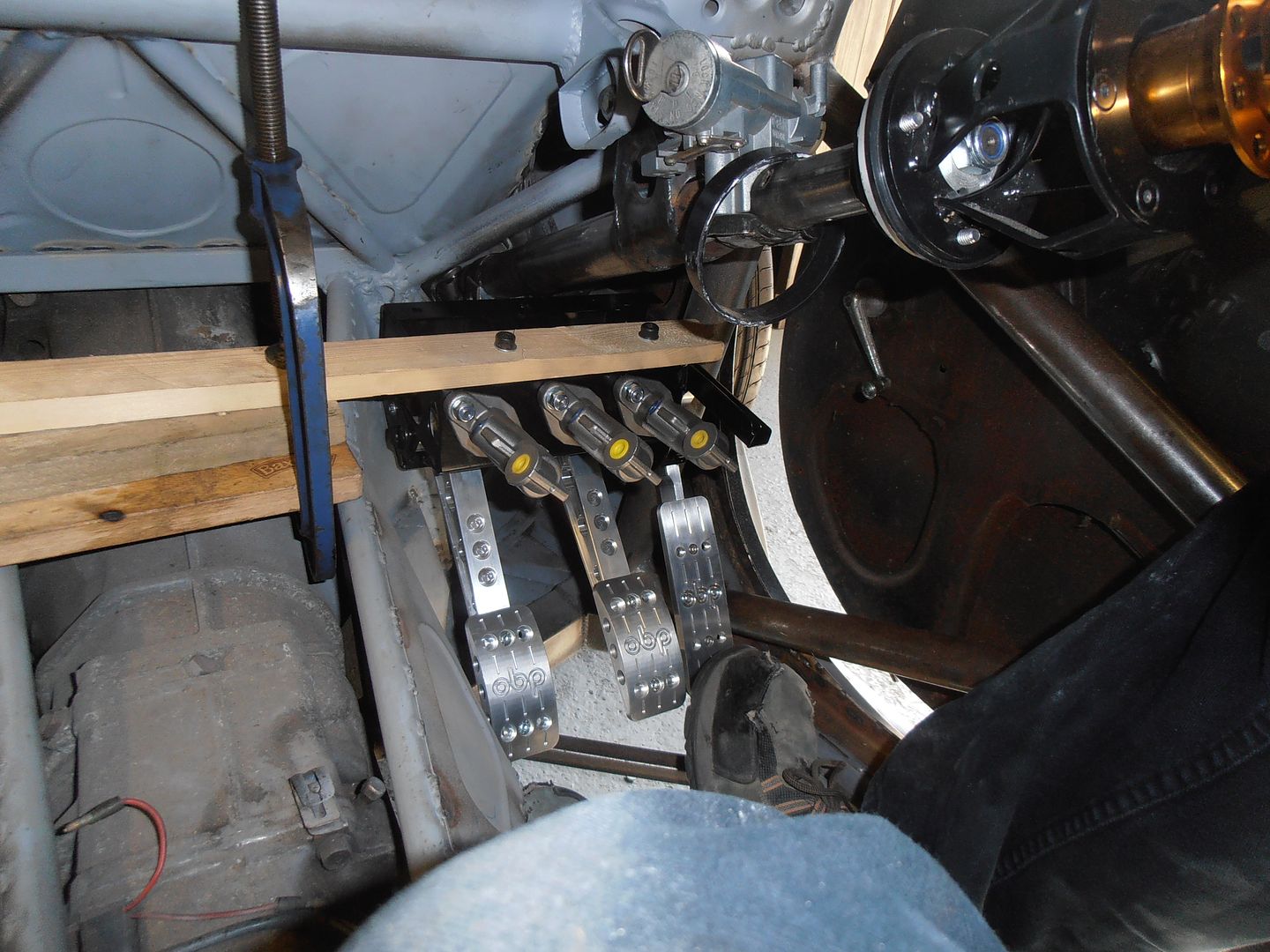 What would help is if I could raise it another 10 - 20 mm,but the steering column get in the way. Look at this though, 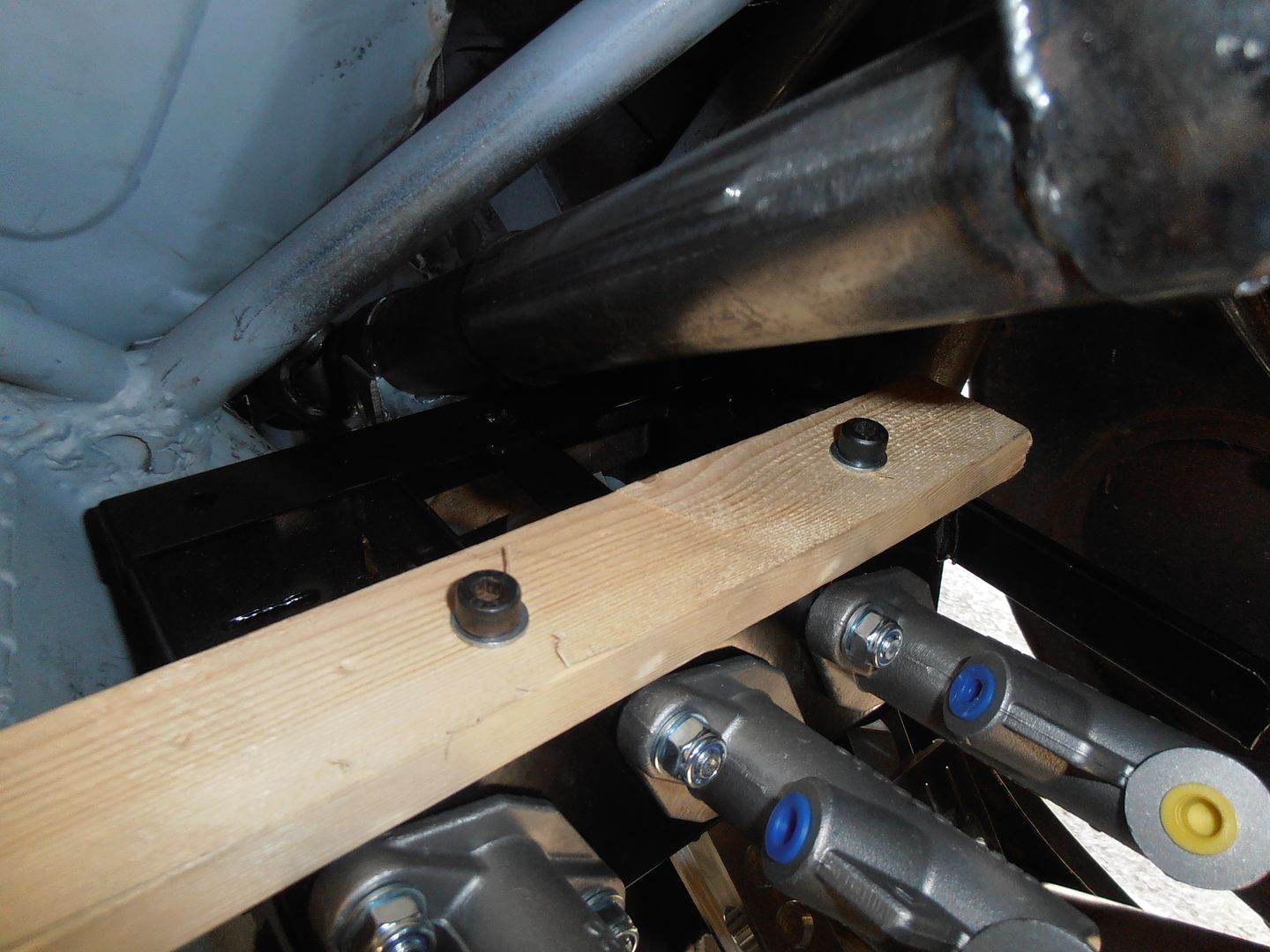 It looks like I can scarf out the back of the pedal box and still have the clearance etc. for the pedals. I will look at it next time when I've got more time. |
| |
|
|
|
|
jonomisfit
Club Retro Rides Member
Posts: 1,789
Club RR Member Number: 49
|
|
Jul 23, 2017 19:35:02 GMT
|
Well, what was meant to be a quick job finishing off the changeover switch on the lathe turned into a bit of an effort. Eventually i got it all put together and working. 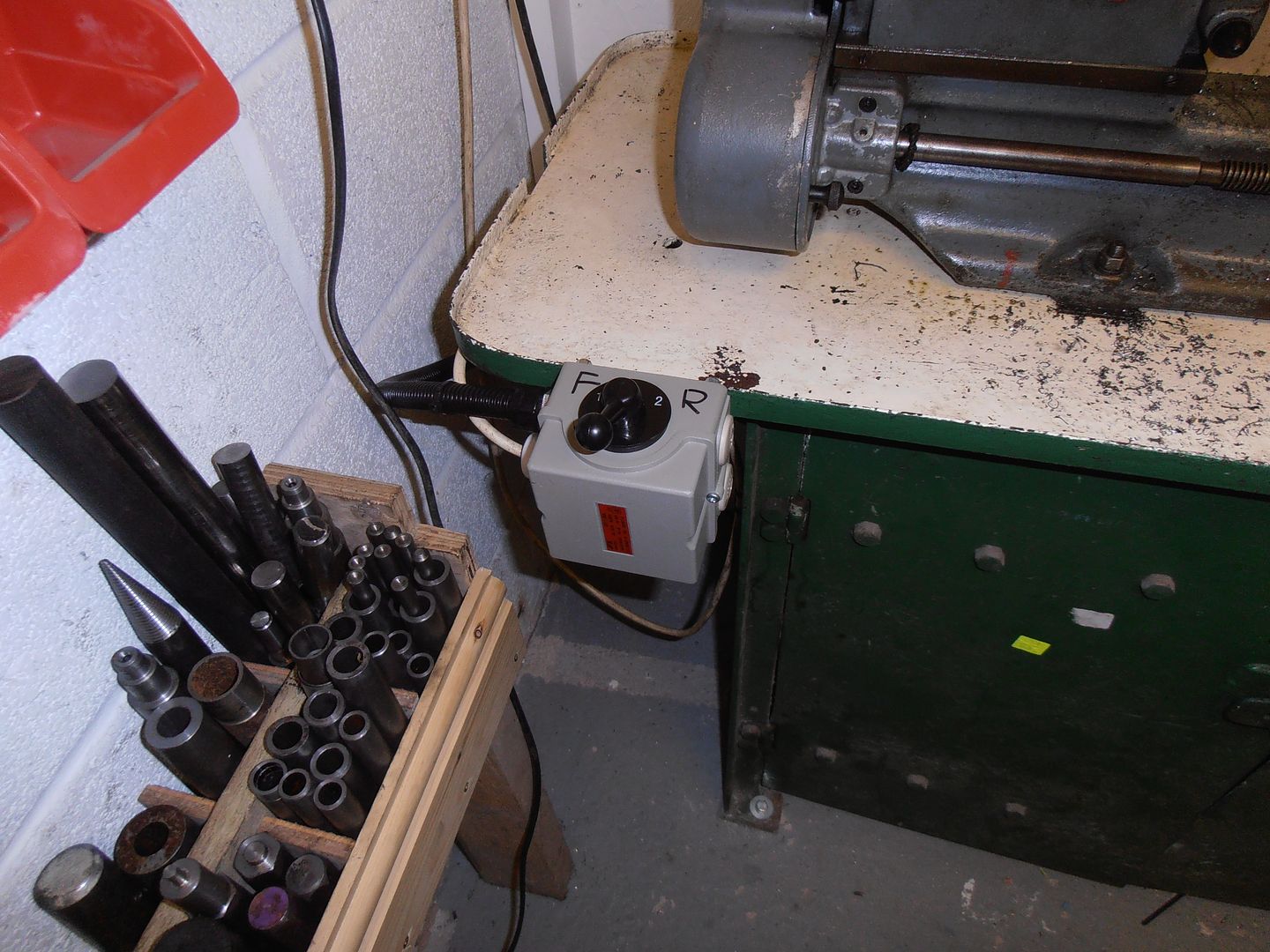 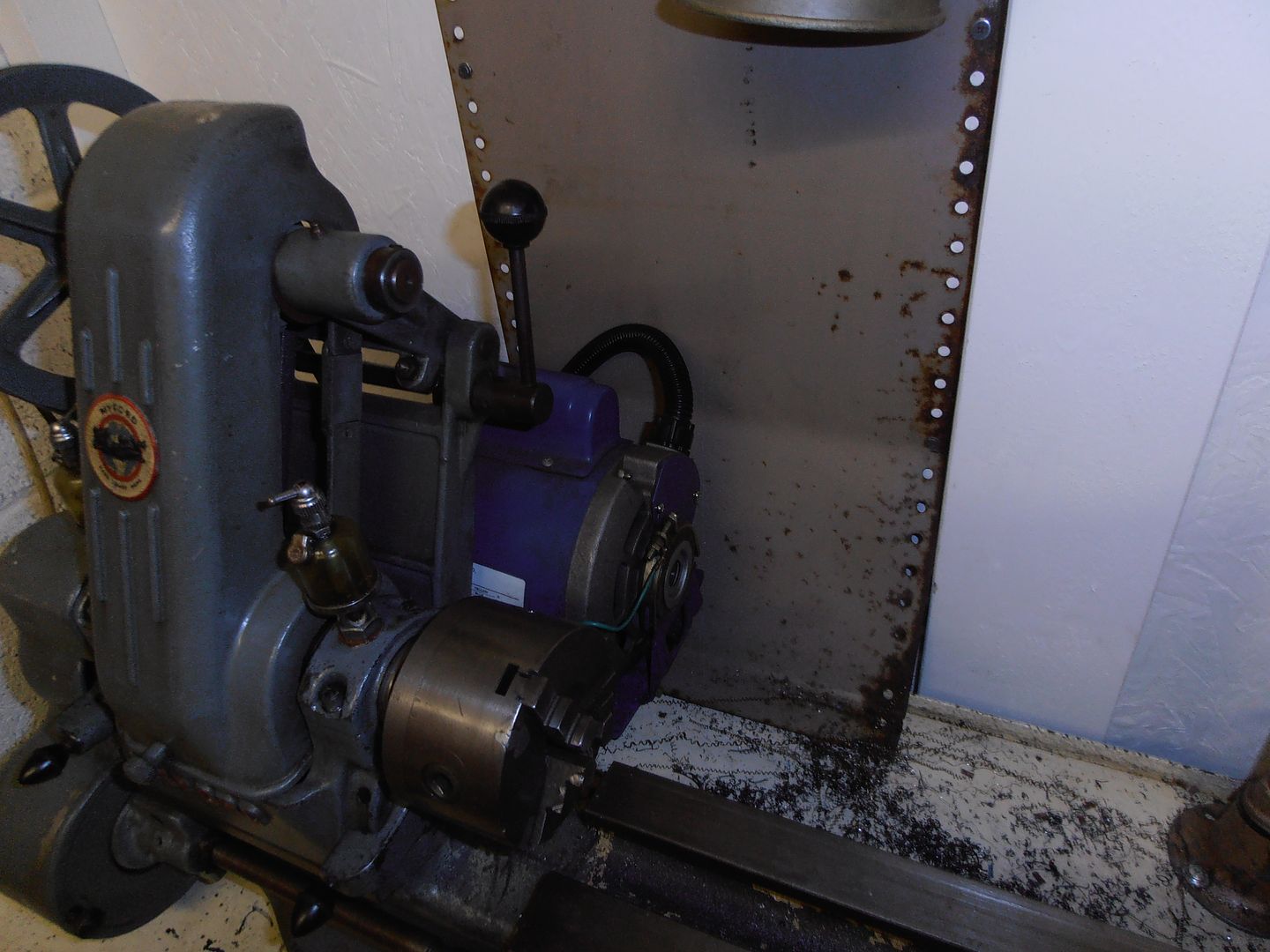 The wiring diagrams on the web are pants, and i had to go back to scratch to work it out for myself. It works, which is the main thing. the whole reason for doing this was to make it easier to screw cut. Something i've never attempted. But having set the lathe up I thought i'd have a bash. very blurry pics 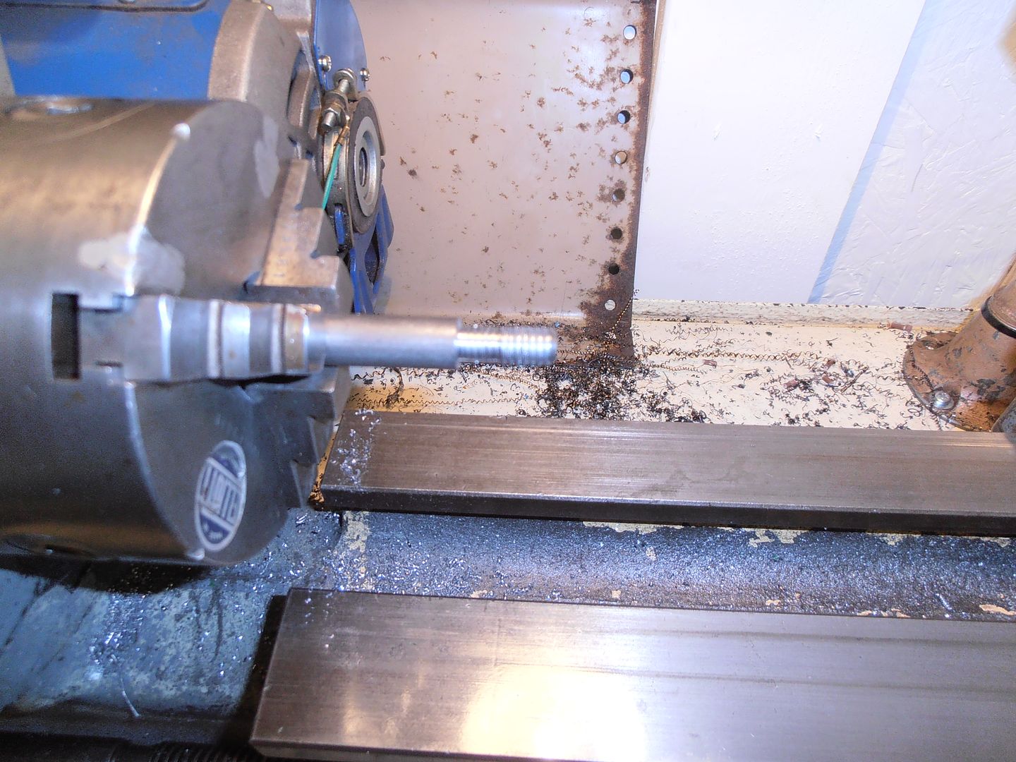 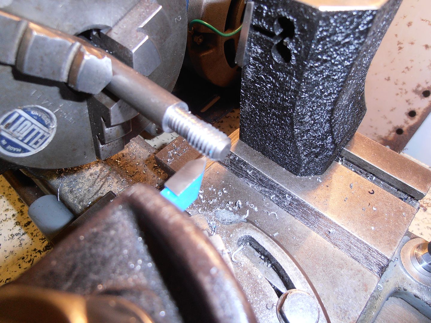 But it turned out it was fairly straightforward in the end, after i worked out what it meant by which gear goes where. 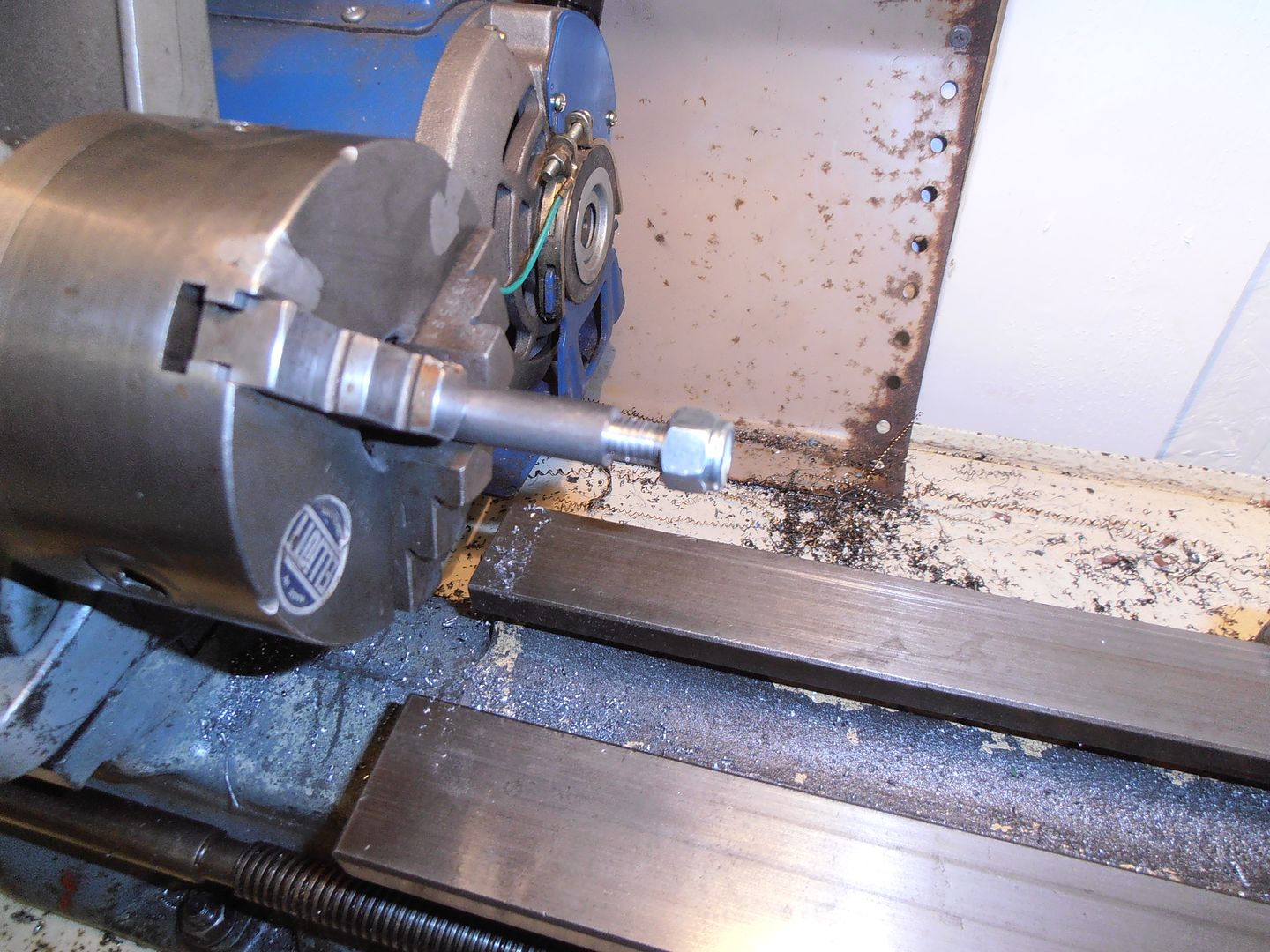 Probably not the worlds best cut thread but seemed an OK fit to me. |
| |
|
|
|
|
|
|
|
I see what you did there... |
| |
|
|
jonomisfit
Club Retro Rides Member
Posts: 1,789
Club RR Member Number: 49
|
|
|
|
|
It made me smile, even if no-one else noticed it.
|
| |
|
|
|
|
|
Jul 25, 2017 10:41:28 GMT
|
|
What stops that set up just spinning the chuck off?
|
| |
|
|
jonomisfit
Club Retro Rides Member
Posts: 1,789
Club RR Member Number: 49
|
|
Jul 25, 2017 17:34:17 GMT
|
|
Friction mainly. From spindle thread to chuck.
It takes quite an effort to start to wind the chuck off once its seated.
I've no intention of cutting in reverse so there's never a load in the unwind direction to initiate the movement and I can't see the chuck self spinning on start.
Standard ml7 setup.
|
| |
|
|
|
|
|
Jul 25, 2017 18:14:15 GMT
|
|
I don't understand.
Your not cutting in reverse?
Why did you need to be able to reverse the motor?
|
| |
|
|
|
|
|
Jul 25, 2017 18:24:40 GMT
|
I don't understand. Your not cutting in reverse? Why did you need to be able to reverse the motor? Because you cannot disengage the feed when thread cutting,and wind the carriage back to the start of your thread,without losing your position. Hence leaving the feed engaged and reversing the motor. You never cut in both directions as the backlash in the lead screw mullers your thread..If you want to cut left hand threads,you can still cut them with normal rotation,just start chuck side and thread towards the tailstock...😊 |
| |
Last Edit: Jul 25, 2017 18:26:32 GMT by Deleted
|
|
|
|
|
Jul 25, 2017 18:33:05 GMT
|
|
Oh, I see.
I knew about left hand threads, I havent done any thread cutting on my lathe but I'm pretty sure I can disengage drive to the carriage without loosing position.
Makes sense now.
edit...
been thinking through how my lathe works and yes, it does engange/disengage leadscrew drive without loosing place.
|
| |
Last Edit: Jul 25, 2017 18:39:28 GMT by VW
|
|
|
|
|
Jul 25, 2017 18:42:02 GMT
|
Oh, I see. I knew about left hand threads, I havent done any thread cutting on my lathe but I'm pretty sure I can disengage drive to the carriage without loosing position. Makes sense now. Well try it,but I think you will find it doesn't work. Some of the top class toolroom lathes,had an indicator on them that you could disengage the leadscrew. You then had an indicator to watch when you re engaged.. Most lathes don't have this feature.... |
| |
|
|
|
|
|
|
|
Jul 25, 2017 18:47:17 GMT
|
|
On my lathe drive is taken as normal from the end of the spindle, through the normal interchangable gears down to a shaft that goes back under the spibdle and along underneath the bed. Halfway down is a lever that slides a connection in the shaft to engage or disengage.
when it gets to the tailstock end another gear links it to the leadscrew.
the sliding connector in the middle of the shaft can only engage one way.
Make sense? I may not be explaining it well.
Its a 115 year old drummond.
edit...
now ive explained it I'm not so sure again lol.
|
| |
Last Edit: Jul 25, 2017 18:50:14 GMT by VW
|
|
jonomisfit
Club Retro Rides Member
Posts: 1,789
Club RR Member Number: 49
|
|
Jul 25, 2017 19:14:37 GMT
|
|
To me its all about locking timing of rotation of the chuck to the carriage location relative to a lead screw position. If you disengage the linkage between these two points you have to have some method of re-establishing the timing point accurately or it will have the tool out of position.
The ml7 lathe has a thread indicator dial that engages on the lead screw independently of the clasp nut, so you can run it in forward, undo the clasp, move the carriage, and then re-engage the clasp at the right time. This however looked fraught with danger of me c0cking it up if i wasnt paying attention, hence the motor reversing.
I could have made a manual winding handle (and i might still for other reasons) but on a long thread its a lot of effort to wind it back. Why do it manually when electricity can do it for me....
|
| |
|
|
|
|
|
Jul 25, 2017 19:24:41 GMT
|
Indeed. I have just been looking at mine. The dissengaging without loosing place would only work on this when cutting the same pitch thread as the leadscrew. As I said, not done any thread cutting yet, not needed to. Ill get my head round it when I'm forced into a situation where I have no choice  |
| |
|
|
jonomisfit
Club Retro Rides Member
Posts: 1,789
Club RR Member Number: 49
|
|
Jul 27, 2017 19:49:42 GMT
|
I had another play at cutting threads today and was interested to know how strong they were compared to a manufactured nut. So turned this up and machined a couple of flats on it 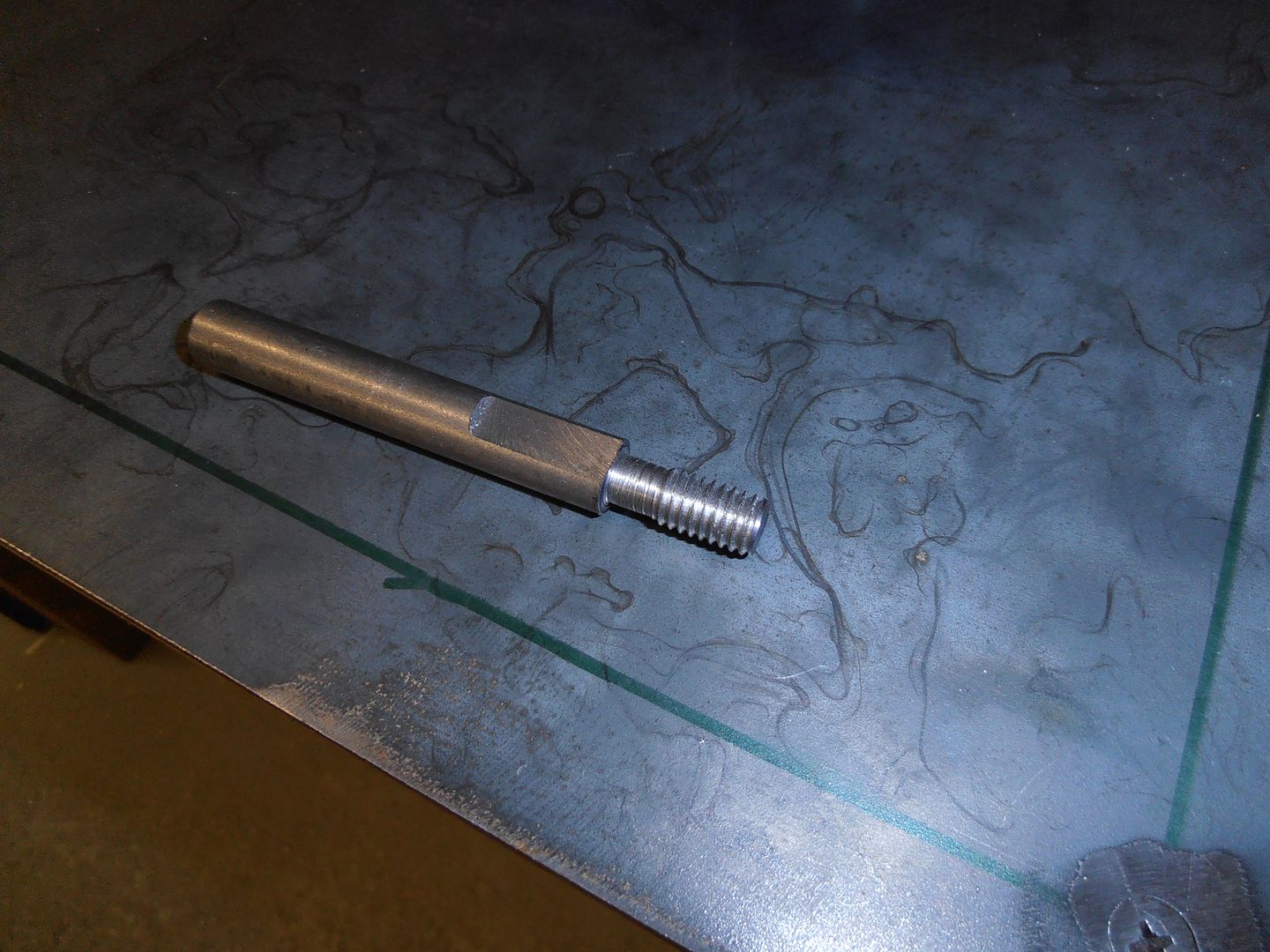 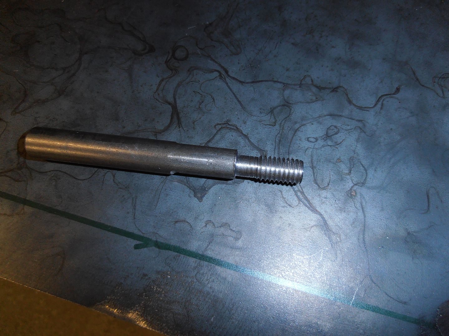 Then fitted it in the vice like thus 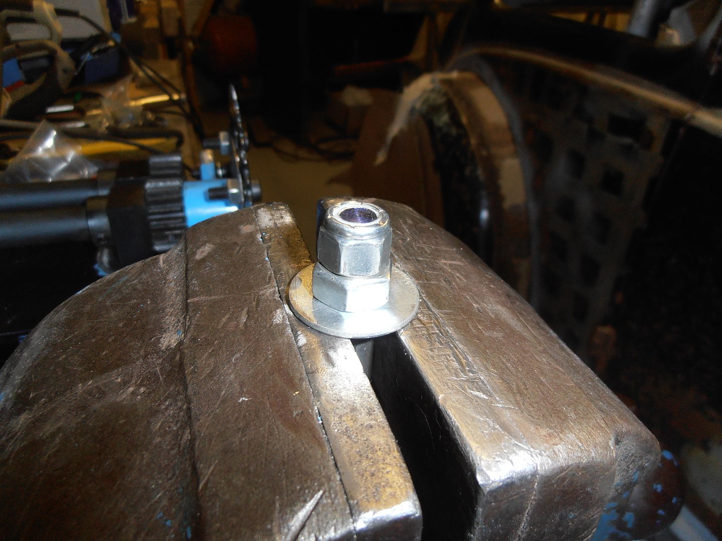 and applied a torque wrench thus 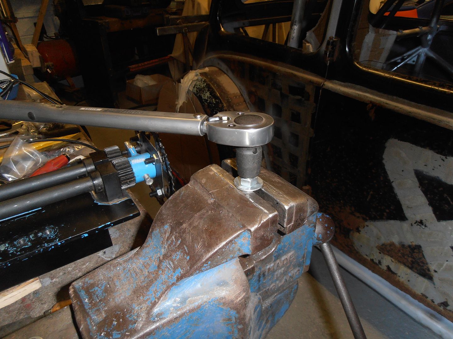 I upped the torque 1nm a time until this happened 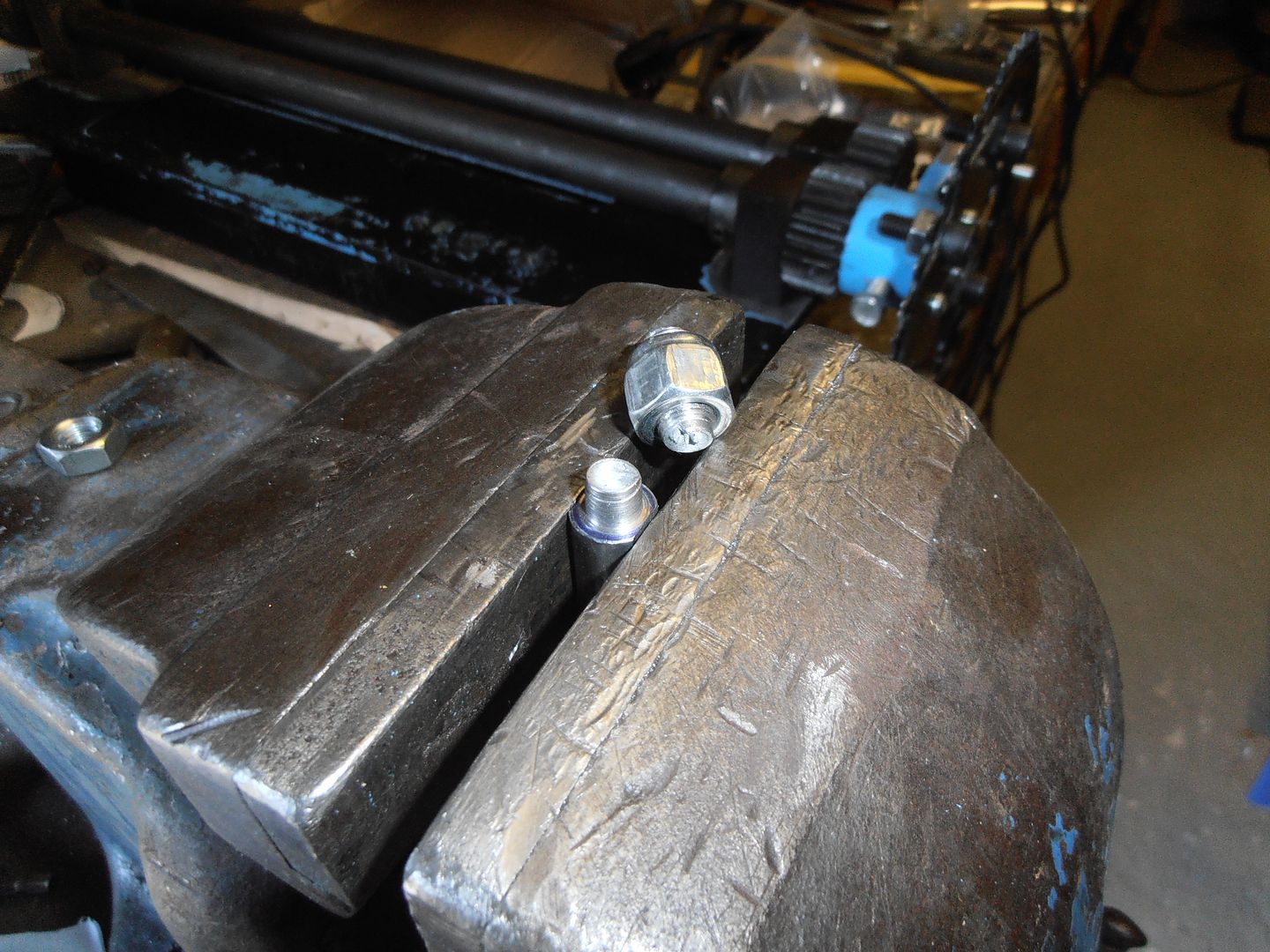 Thread were fine and a nut still ran up them nicely. 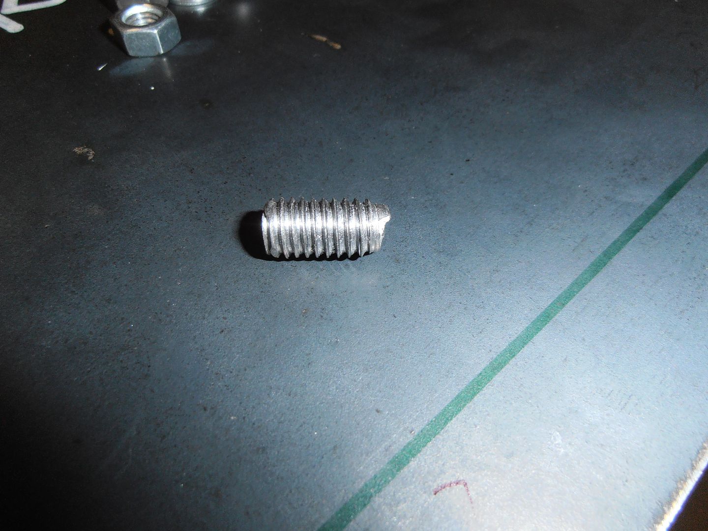 The fracture initiated on the wasted section after the threaded portion where there was a very light witness mark from the thread cutting. I got to 28NM which wasnt bad for the size of thread I cut and mild steel. I was just more interested to see if i'd strip the threads first, indicating i hadnt cut something correctly. So i then moved onto mounting the pedal box. I looked at it and though "this will be a nightmare". It is. Make a better trial / temporary mount 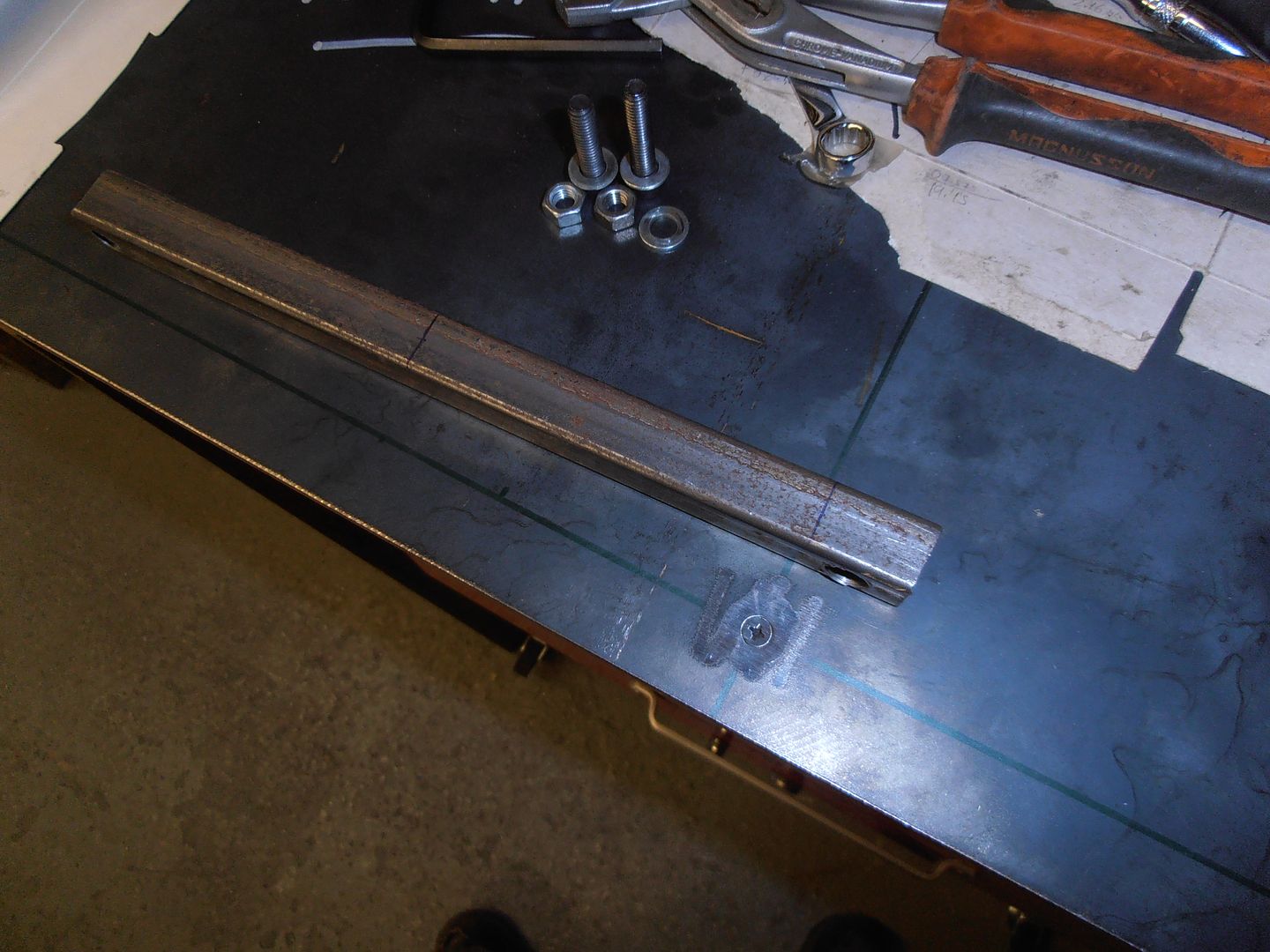 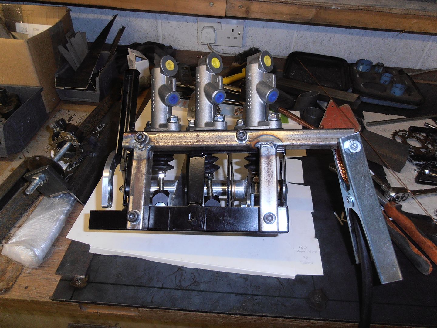 And through the application of different offcuts and clamps located into the car 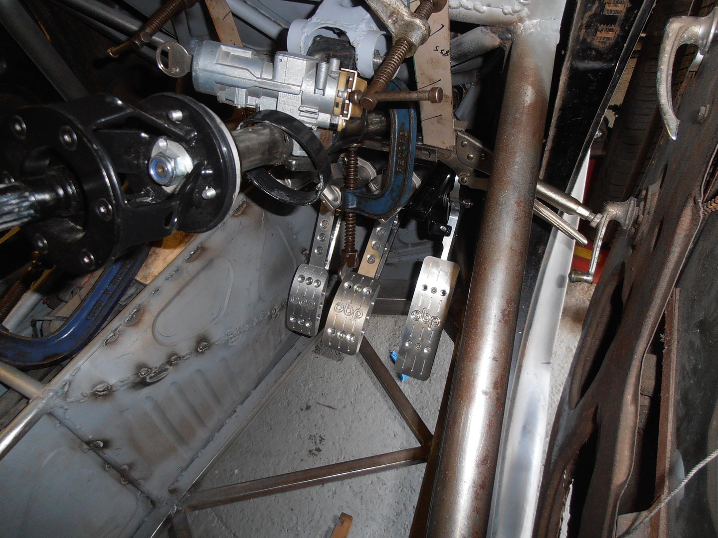 I then spent about an hour adjusting it back and forth trying to get a position i liked. I had to relieve the transmission tunnel cover slightly 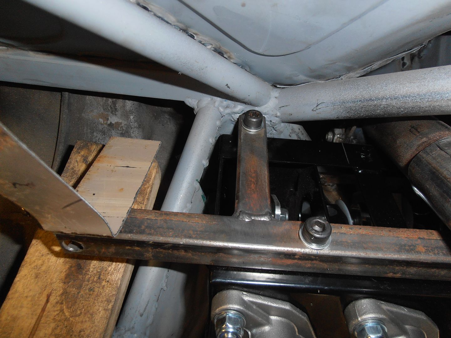 so will need to patch that back up in the future once i'm happy on the position. 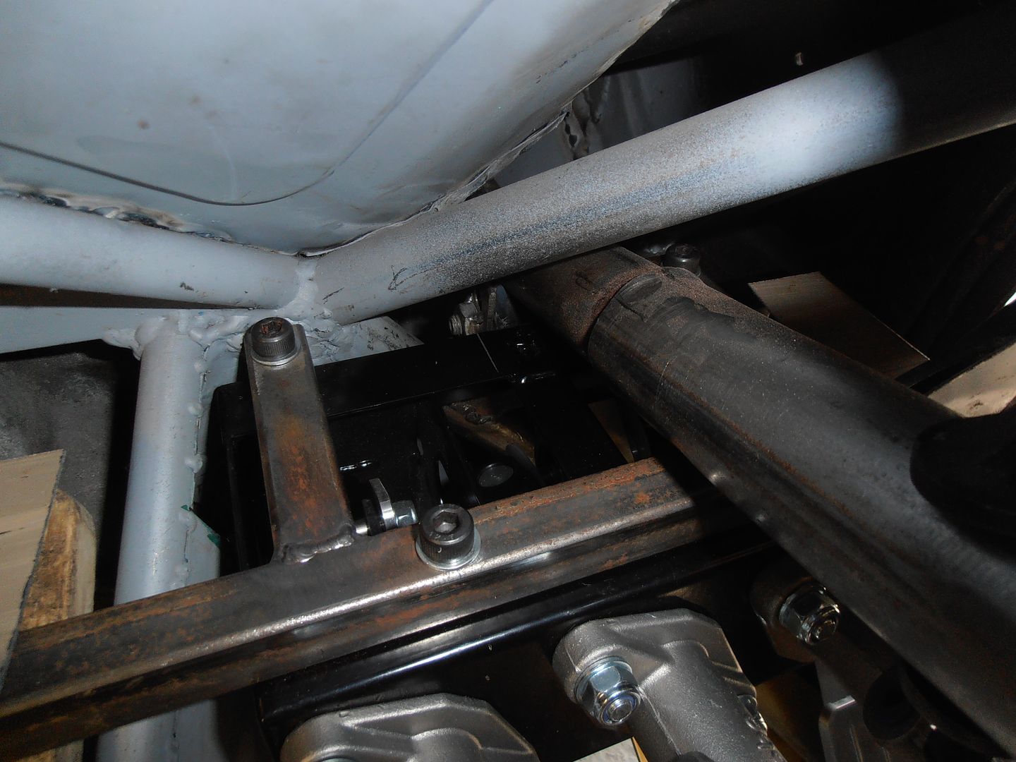 I've also managed to move it left, so the trim i need to do on the back of the pedal box housing no longer is in line with the reinforcing rib on the pedal box. I then spent a while looking at the master cylinders to find out why the brake pedal was pushing so far forward in the returned position. The push rods on the master cylinders are about 20mm too long for the pedal to be in the right position (it pushes much further out than the throttle pedal with the throttle stop wound right in), so need trimmed to size. I incorrectly thought that buying a complete kit from OBP then everything would be bolt together. It isn't and as its generic master cylinders they'll need trimmed. Would be nice if some instruction came with the kit and mentioned this... Anyway a job for another day as Mrs_Misfit and Baby_misfit returned home. |
| |
|
|
jonomisfit
Club Retro Rides Member
Posts: 1,789
Club RR Member Number: 49
|
|
Jul 31, 2017 16:42:11 GMT
|
Back to the bead roller motorification today. I was at my dads so had a look round some of the shelfs of dismantled cars (he has a farm and a number of sheds contain... well a lot of sheds) to see something suitable. I found this, a window wiper mechanism from something fairly heft. 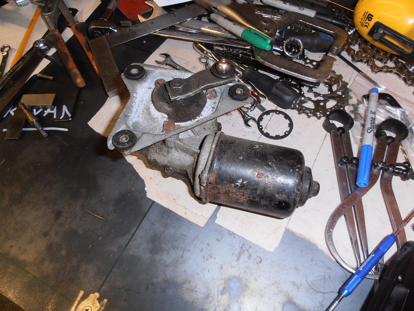 which worked fine when hooked to the battery and seemed to have a fair chug of torque. i needs an adaptor. A lot of hacksawing liberated this from a piece of stock 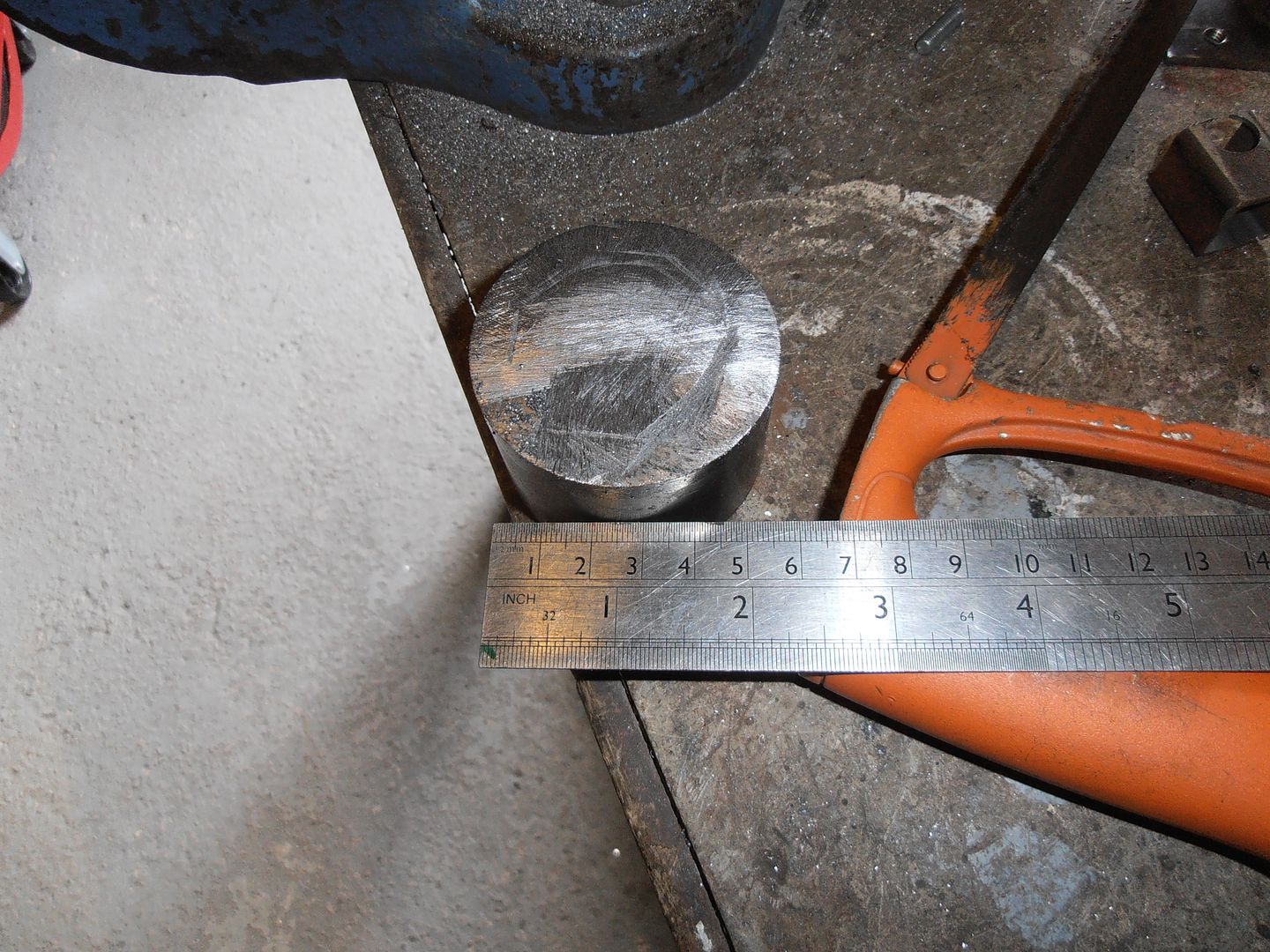 this one 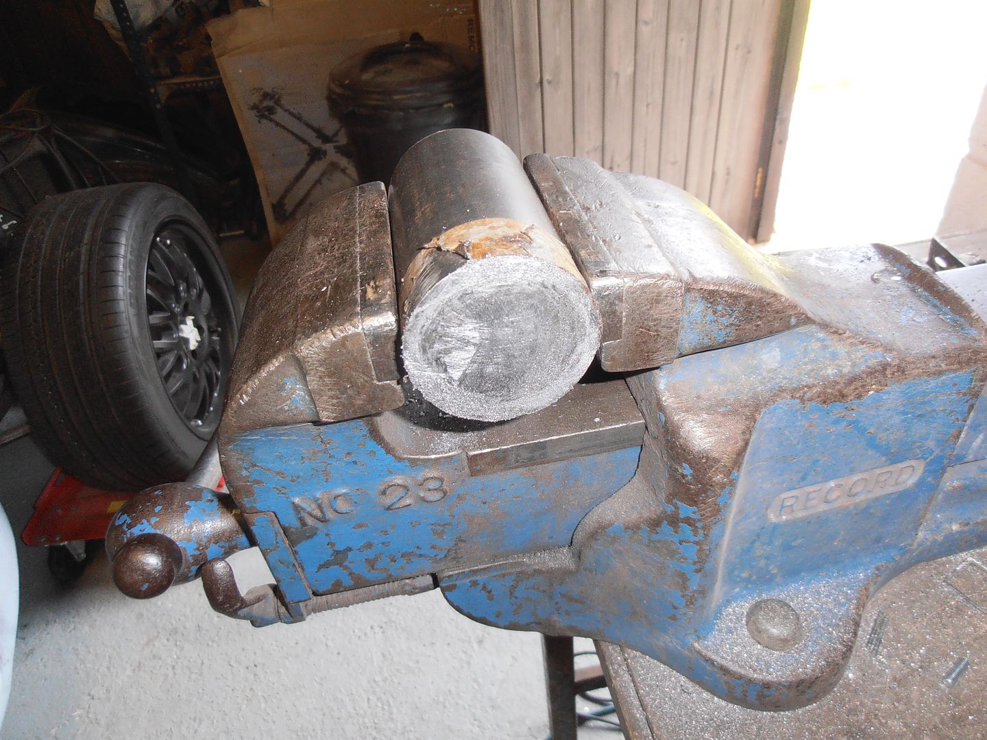 spindle has flats which do the main driving. 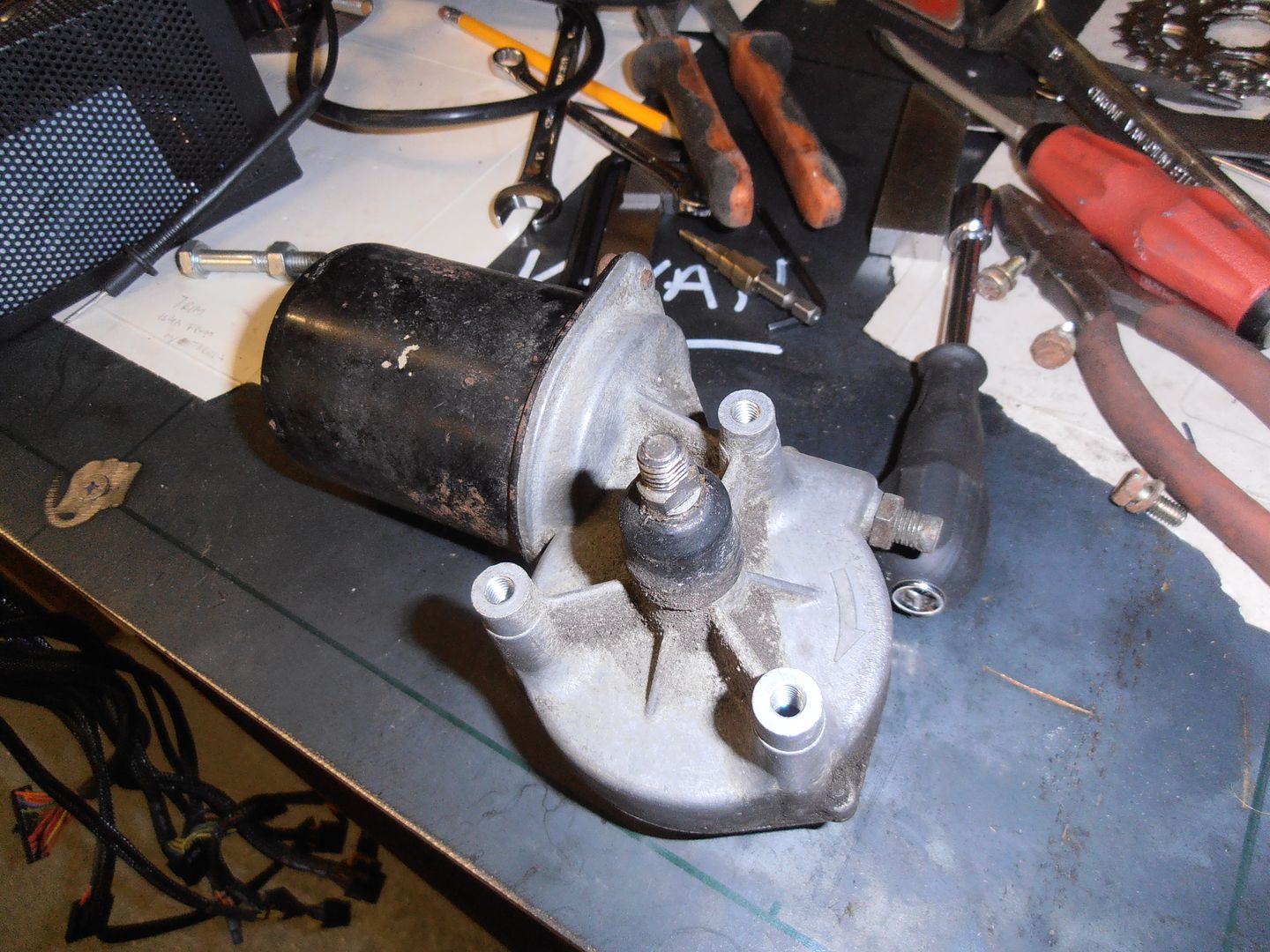 a lot of machining, and forgetting to take pictures later and I have this 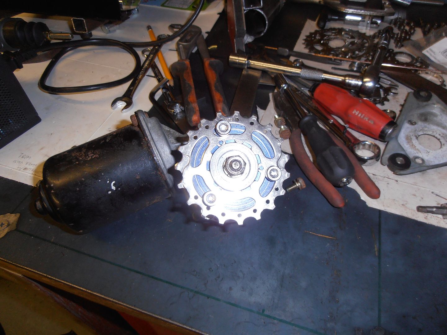 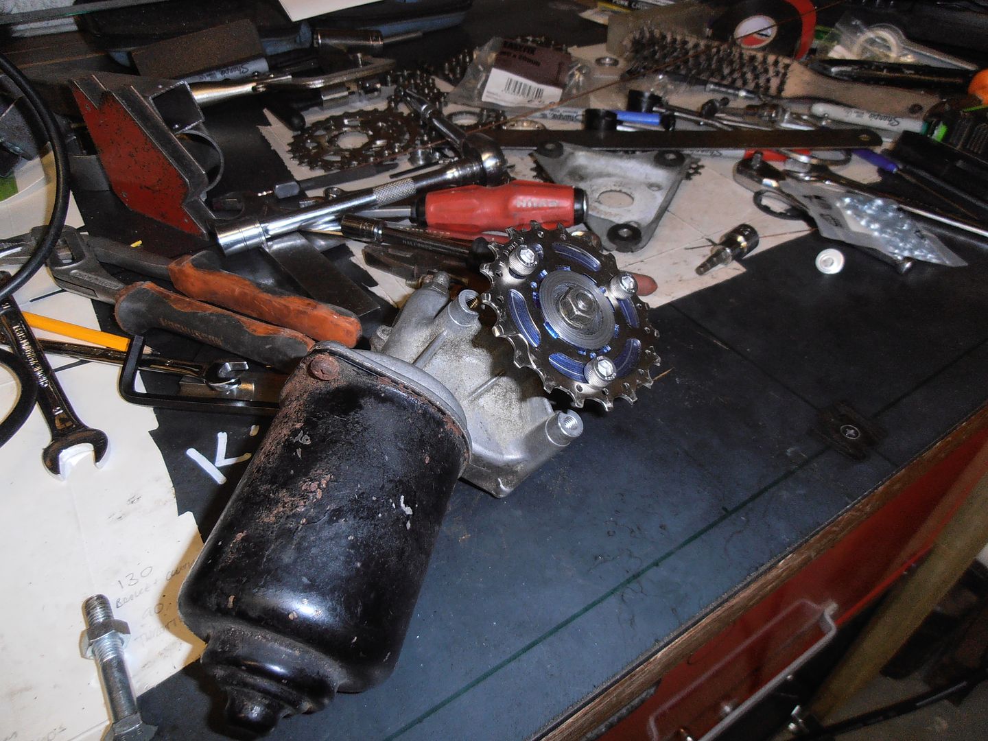 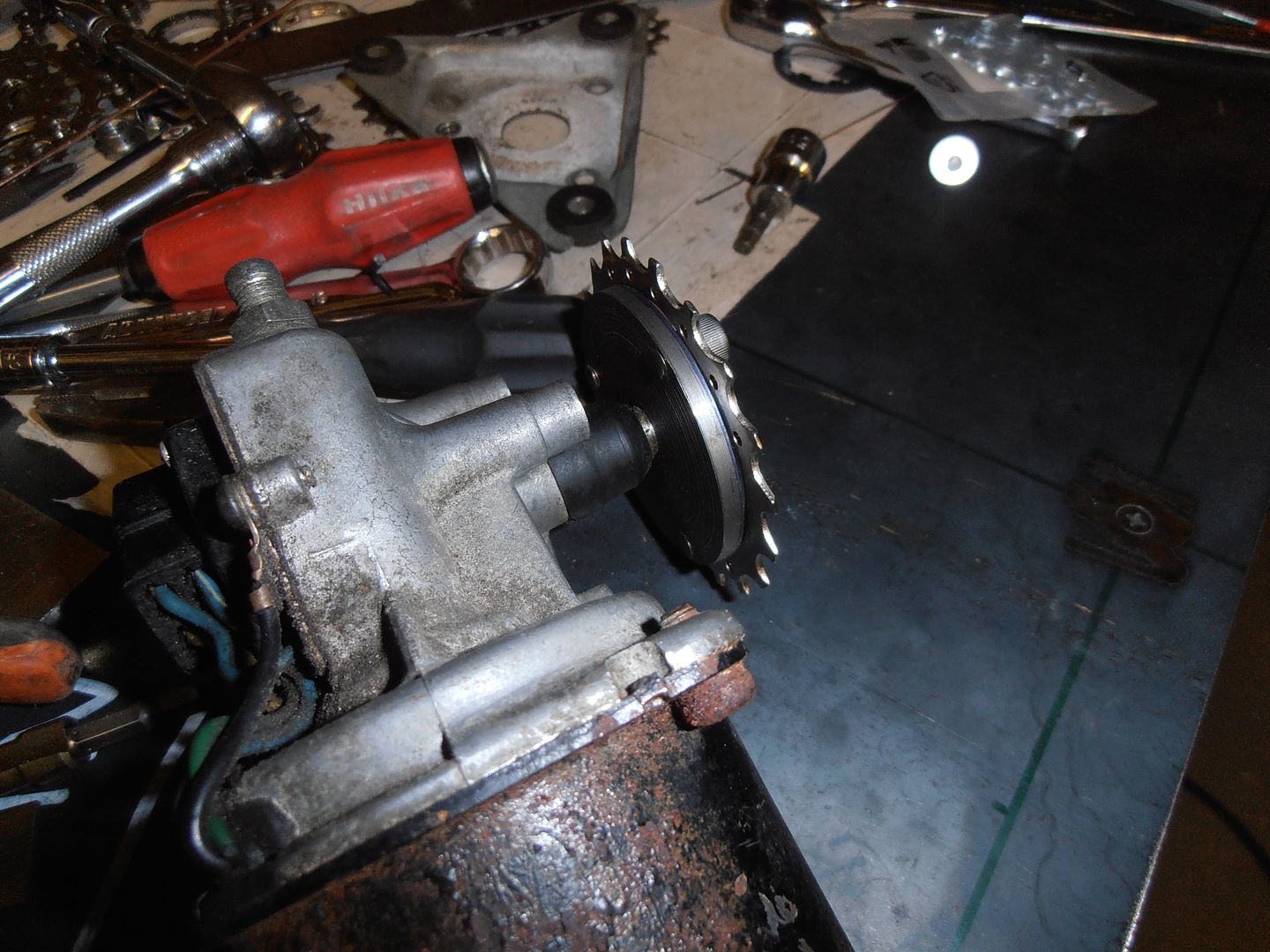 then i need a power supply. I have no spare batterys. Hmmm... hold on i'm sure in the loft 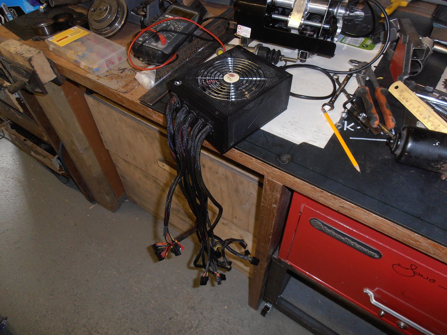 yes, 900w PC power supply lying about which has 12v output A few minutes on the internet to find out how to get power output when not connected to anything and the motor runs nicely from it. Better make a mount 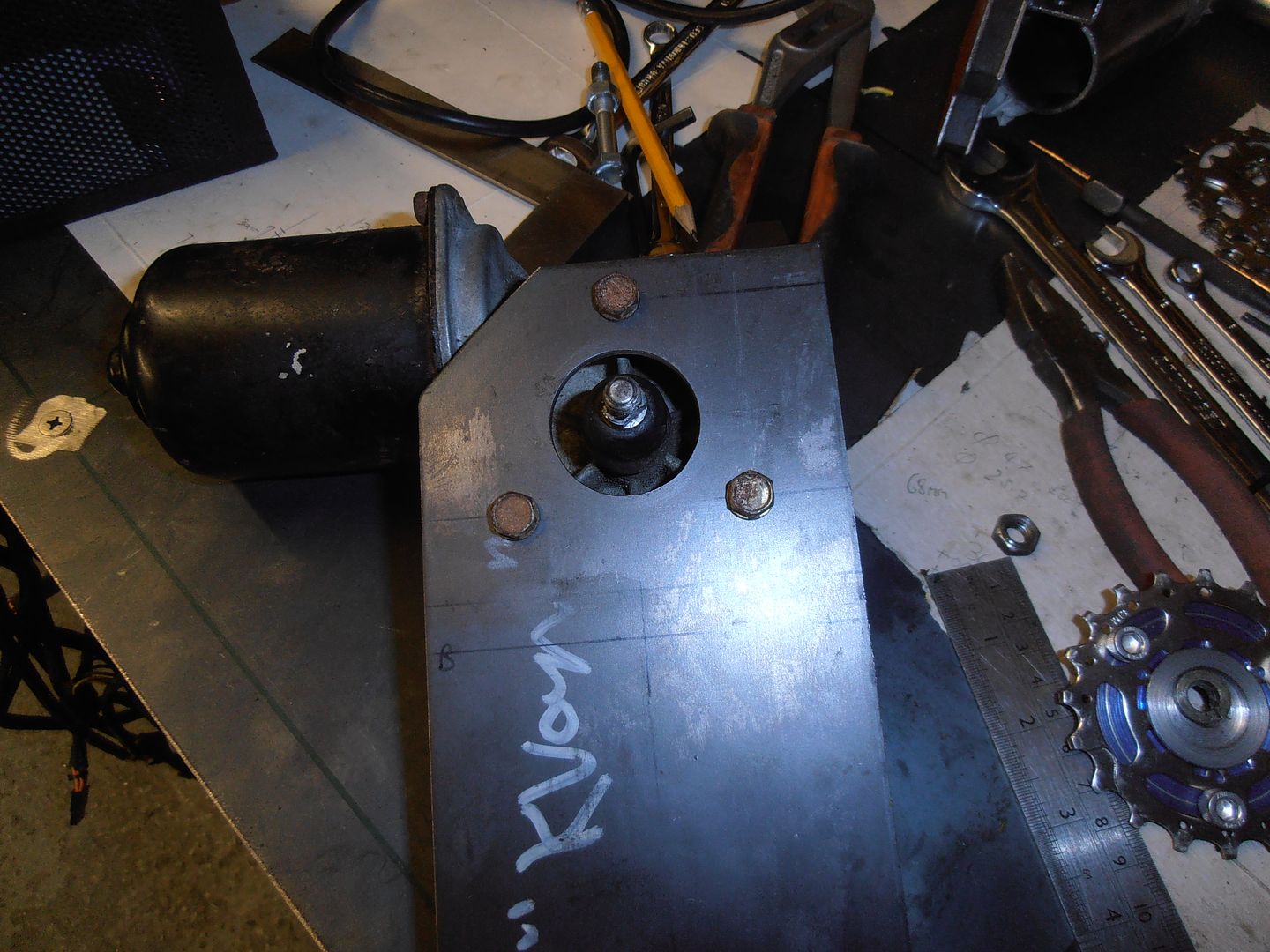 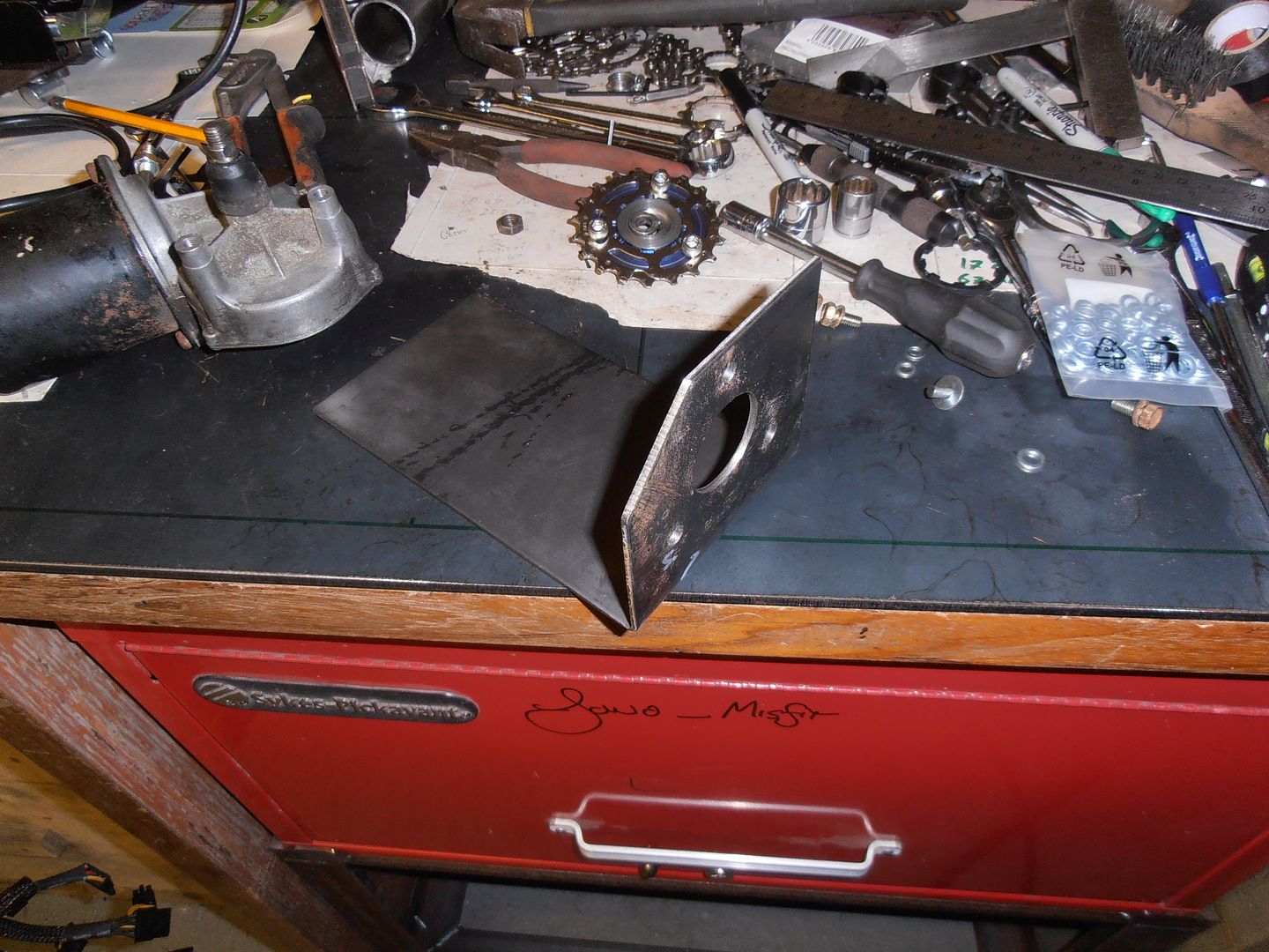 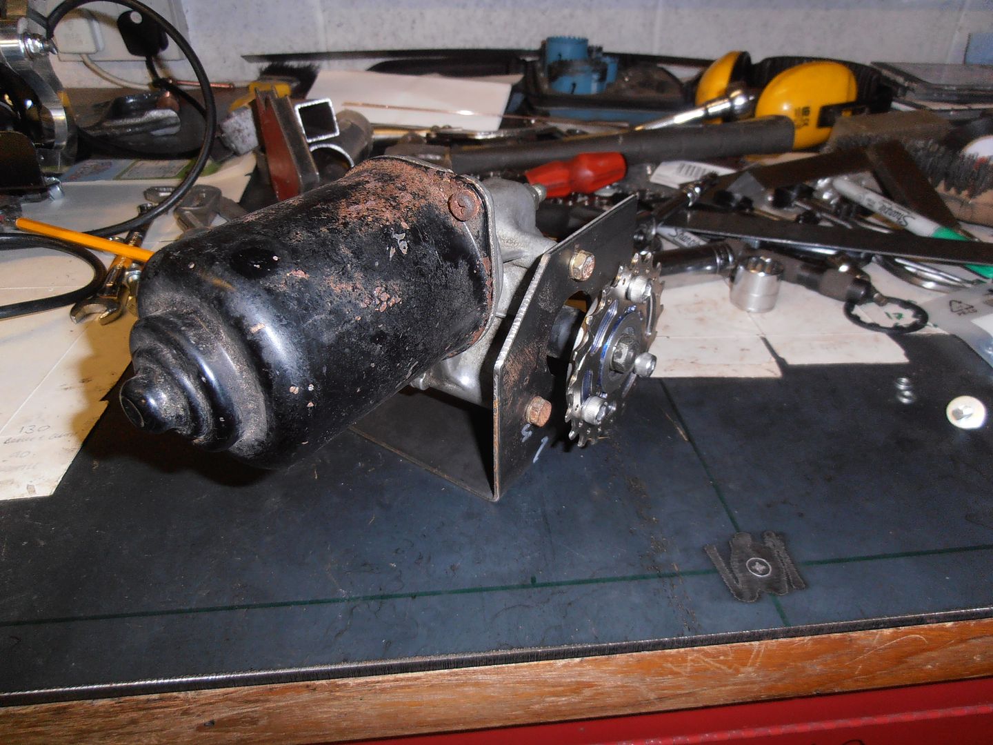 I'll add stiffeners on once I make sure it works ok. temporary clamped together with a temporary tensioner 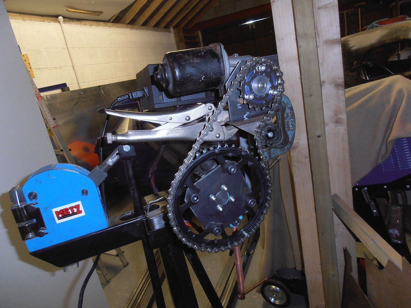 run some test beads and it works very nicely. 0.6,0.8,1.0 all bead really easily at a good controllable speed. i thought, why not give it a challenge, so put some 1.5mm through it. It was not overly happy with this, but it did work. It just needed a couple of passes for the depth. I've never attempted 1.5mm by hand. A success I'd call it. Just got to sort some proper structure and fixings. And make a spring tensioner to manage the chain tension, and probably a guide / guard as well. Next weekends tasks. Whilst at my dads we also dug out a load of pieces for the escort, so overall my attention may be diluted a bit so I can get that going as well. If i do start it i'll stick a suitable thread up. |
| |
|
|
jonomisfit
Club Retro Rides Member
Posts: 1,789
Club RR Member Number: 49
|
|
|
|
I need a tensioner for the chain. I could find something on ebay and be done with it, but i'm not convinced most of the standard bike type ones will work, plus i'm a cheapskate. So a little application of CAD gives an over the top design... 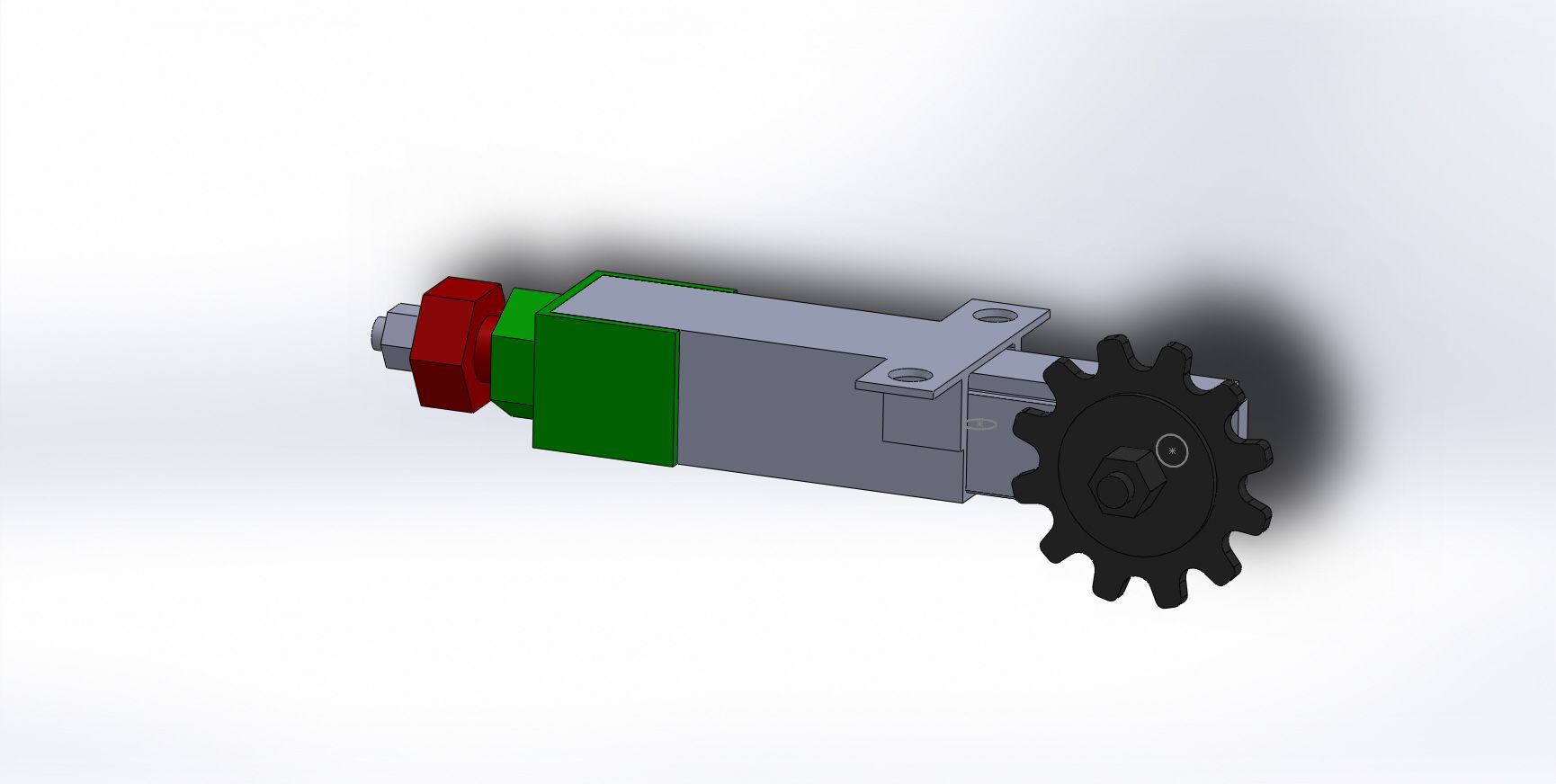 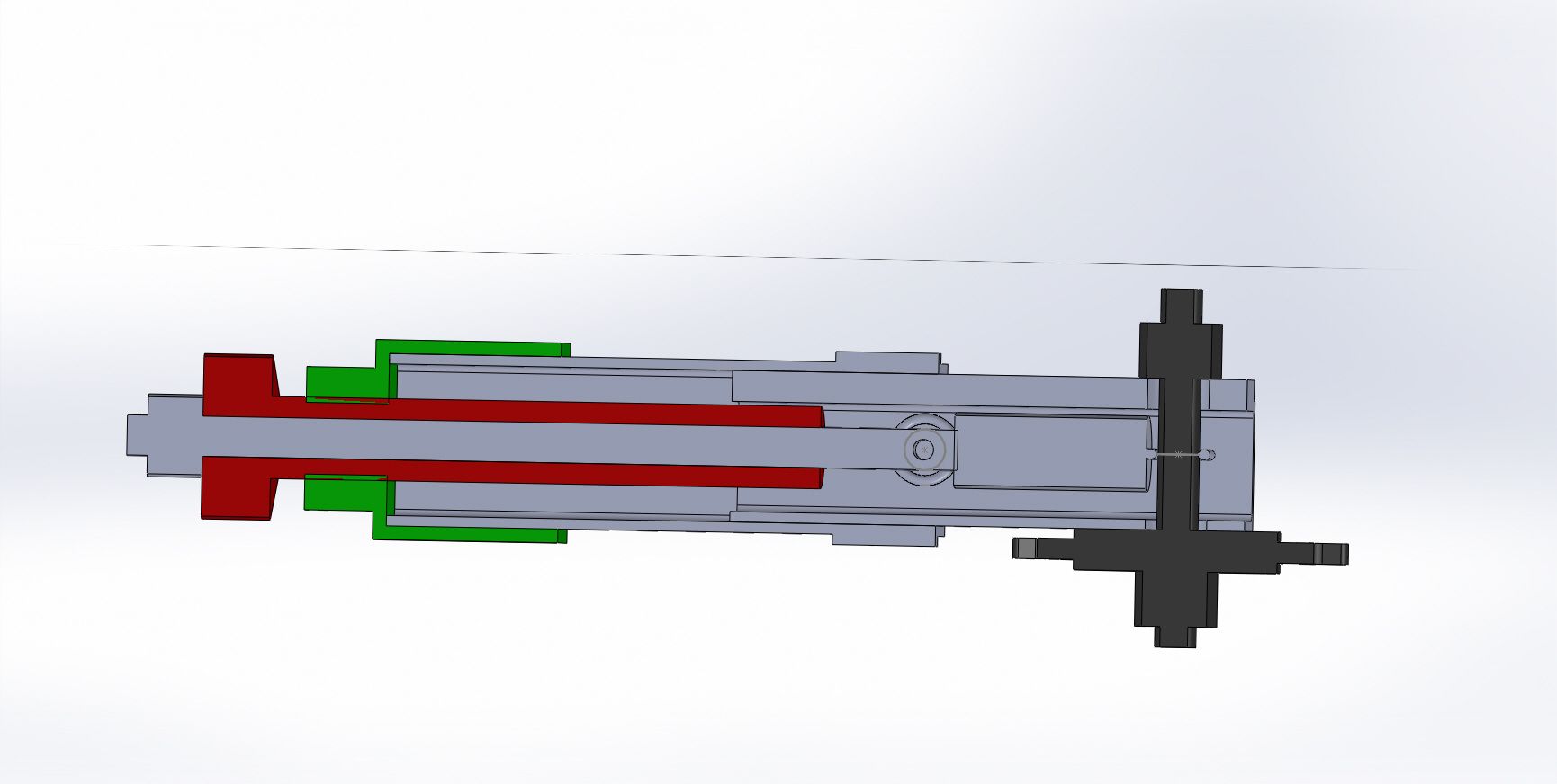 Tension is adjusted by winding the red piece in and out (will be a nut welded to some threaded rod). Probably over the top, but, well, never mind. |
| |
|
|
jonomisfit
Club Retro Rides Member
Posts: 1,789
Club RR Member Number: 49
|
|
|
|
Right, Heath Robinson device manufacture take 1 Body and attachment bracket 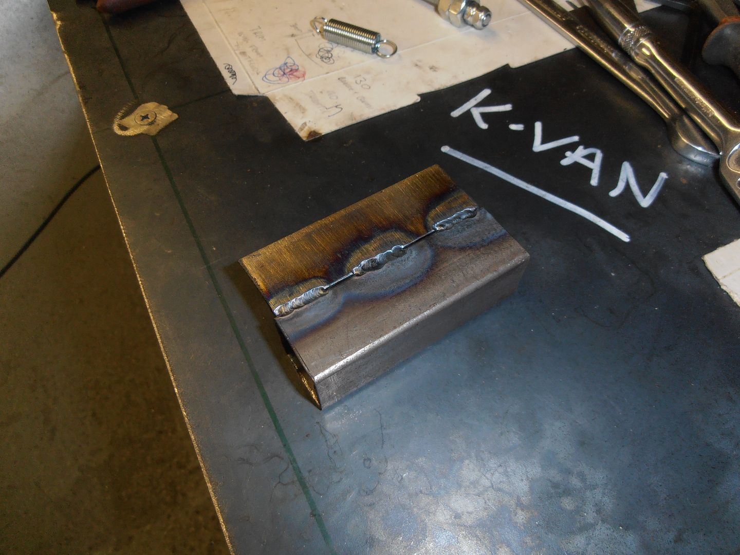 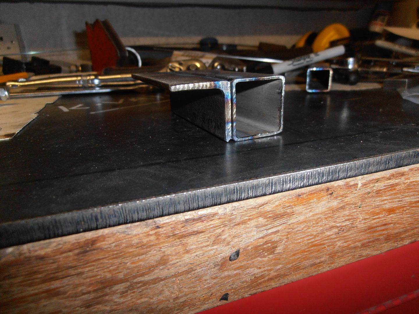 Made the tension adjuster This was slow to do as it was a very long slender drilling, 140mm at 5.5mm followed by 6mm. 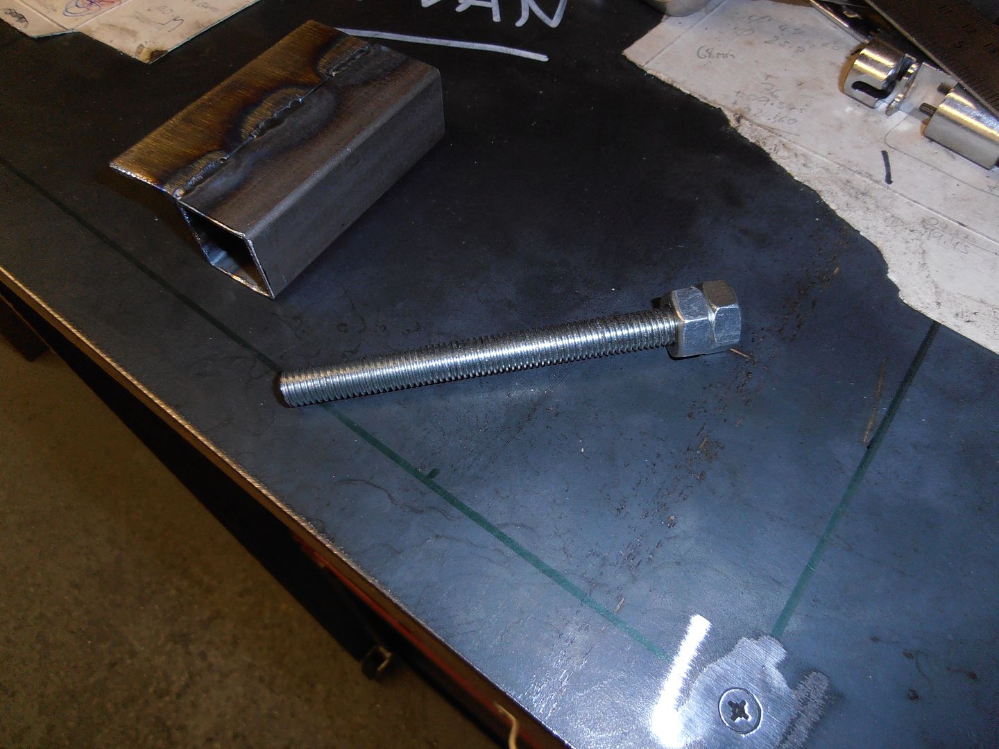 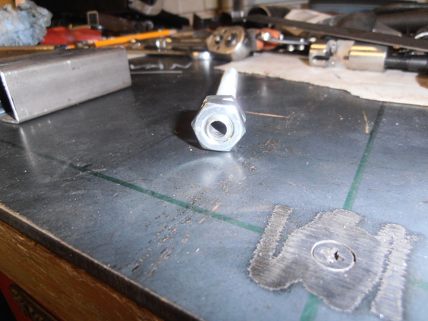 slider body 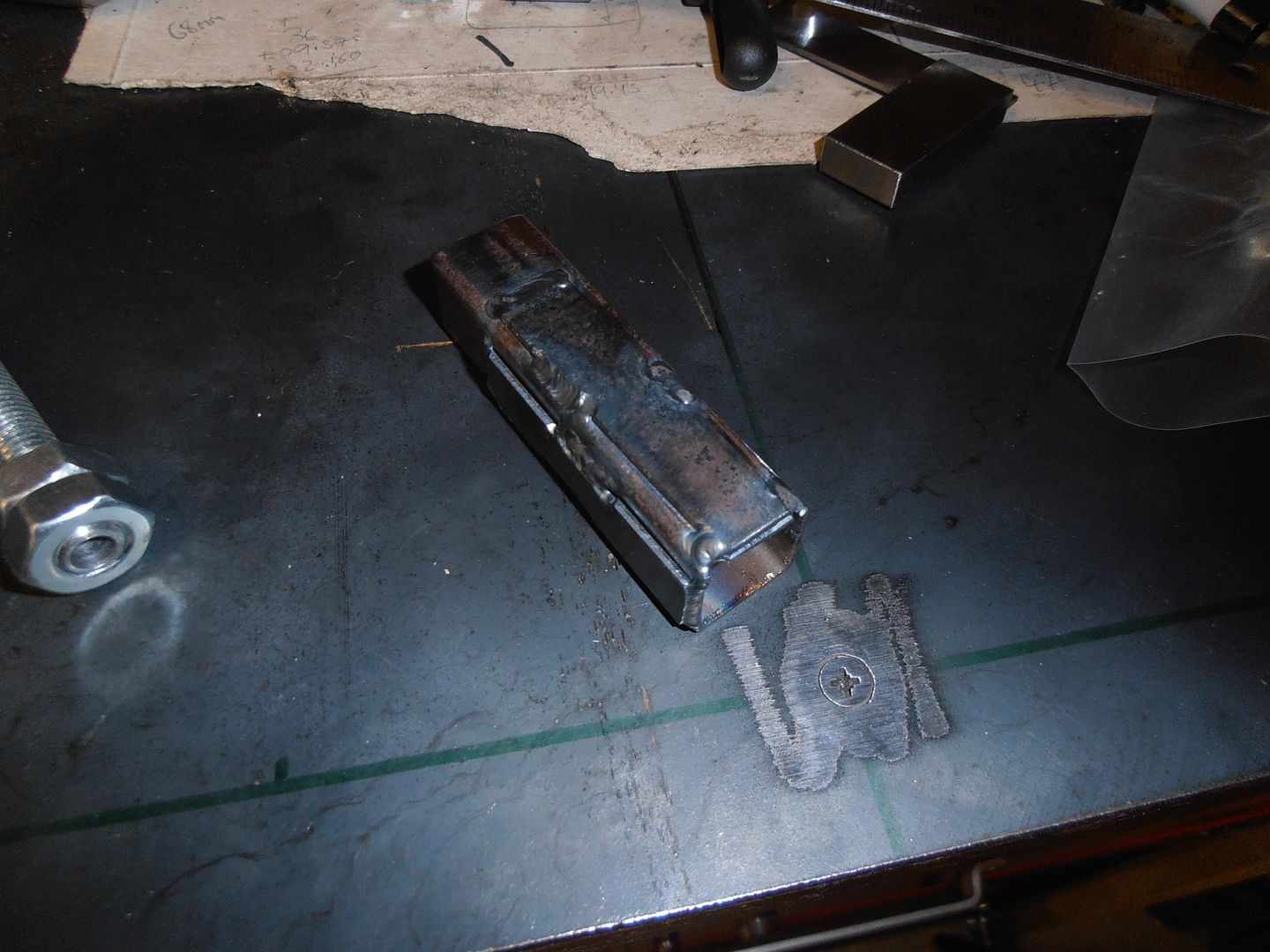 tension rod 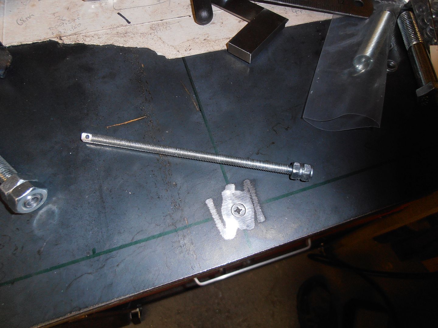 starting to assemble 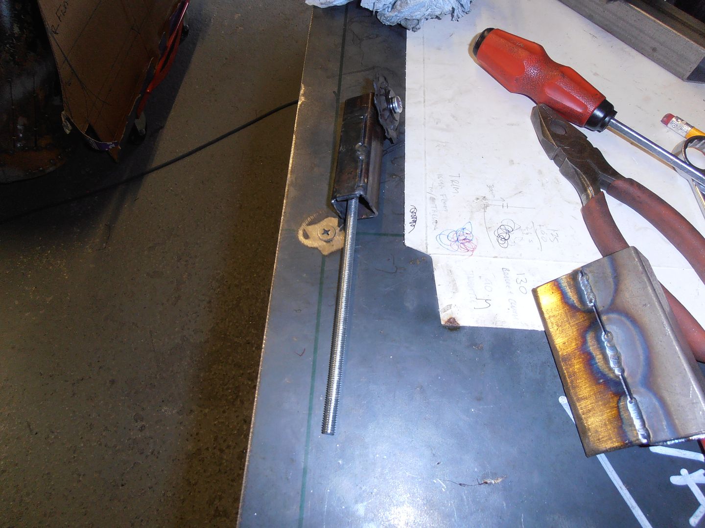 fixed thread added (a nut and closer plate) 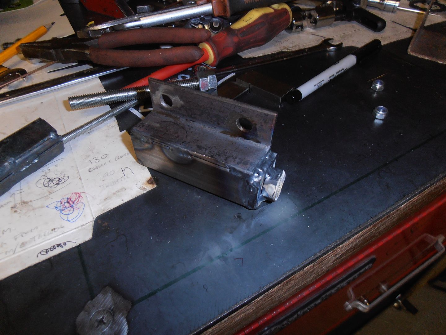 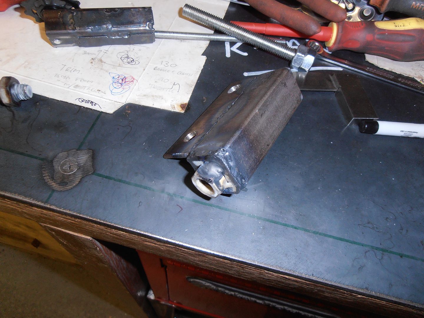 device assembled 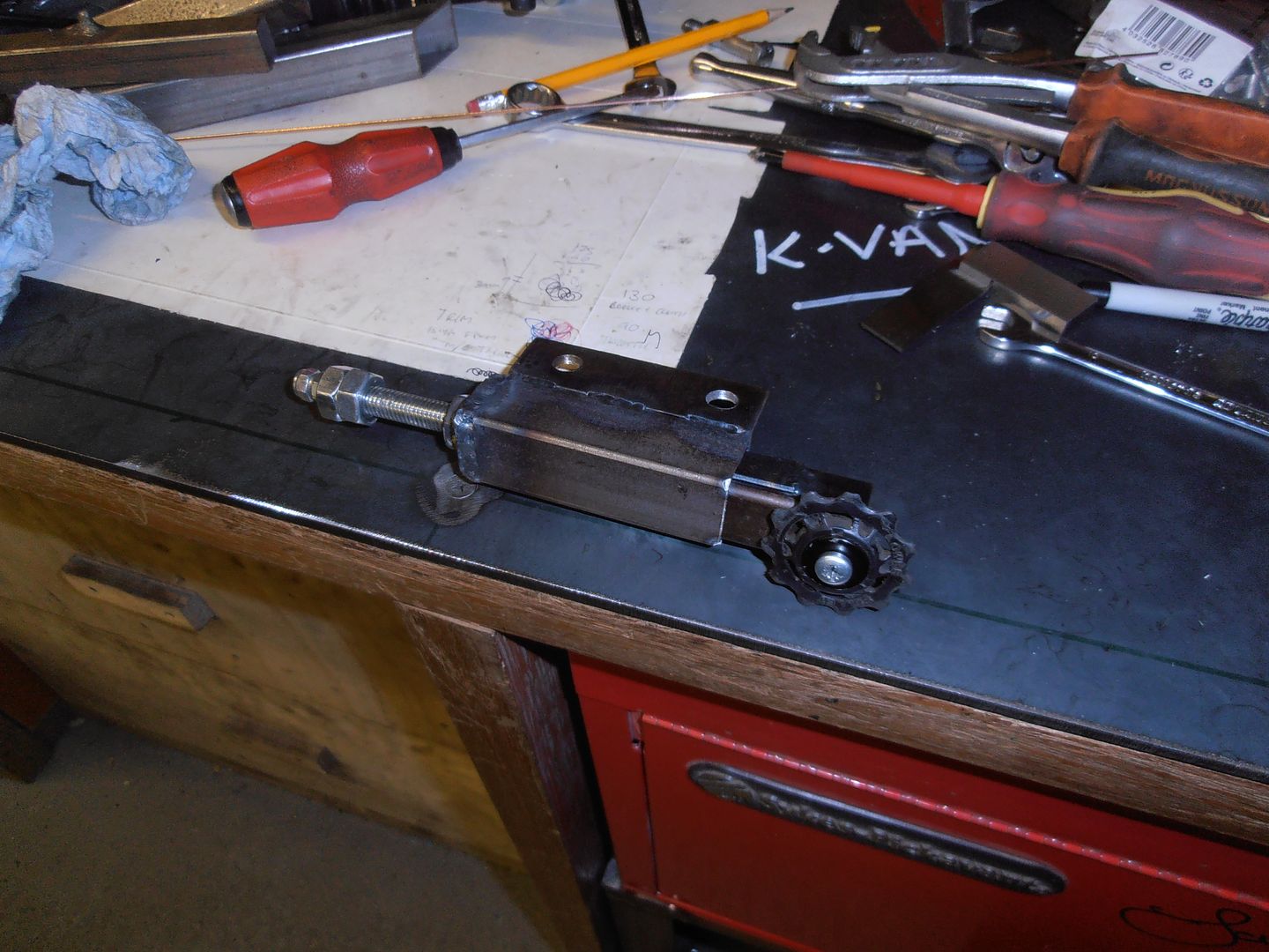 I then needed to add some strengthening gussets to the motor mount 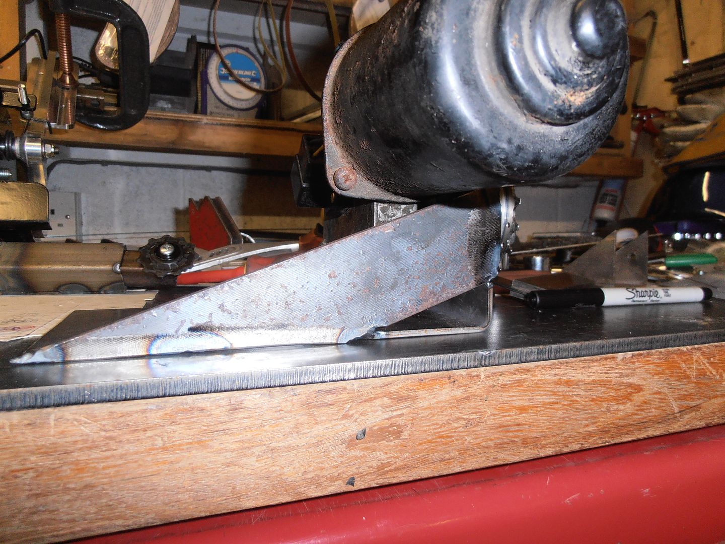 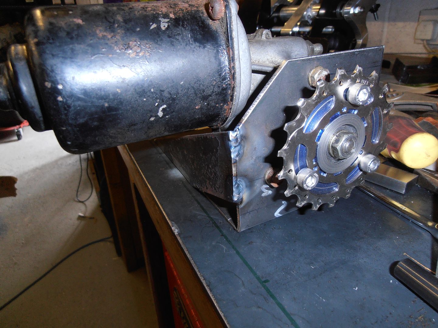 then time for the nervous bit. temporary fit it all up 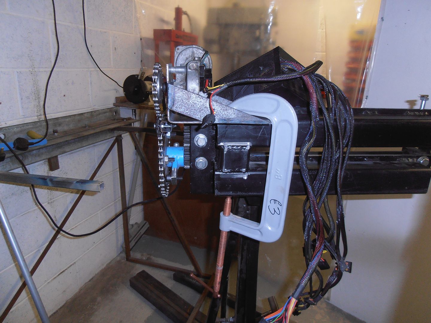 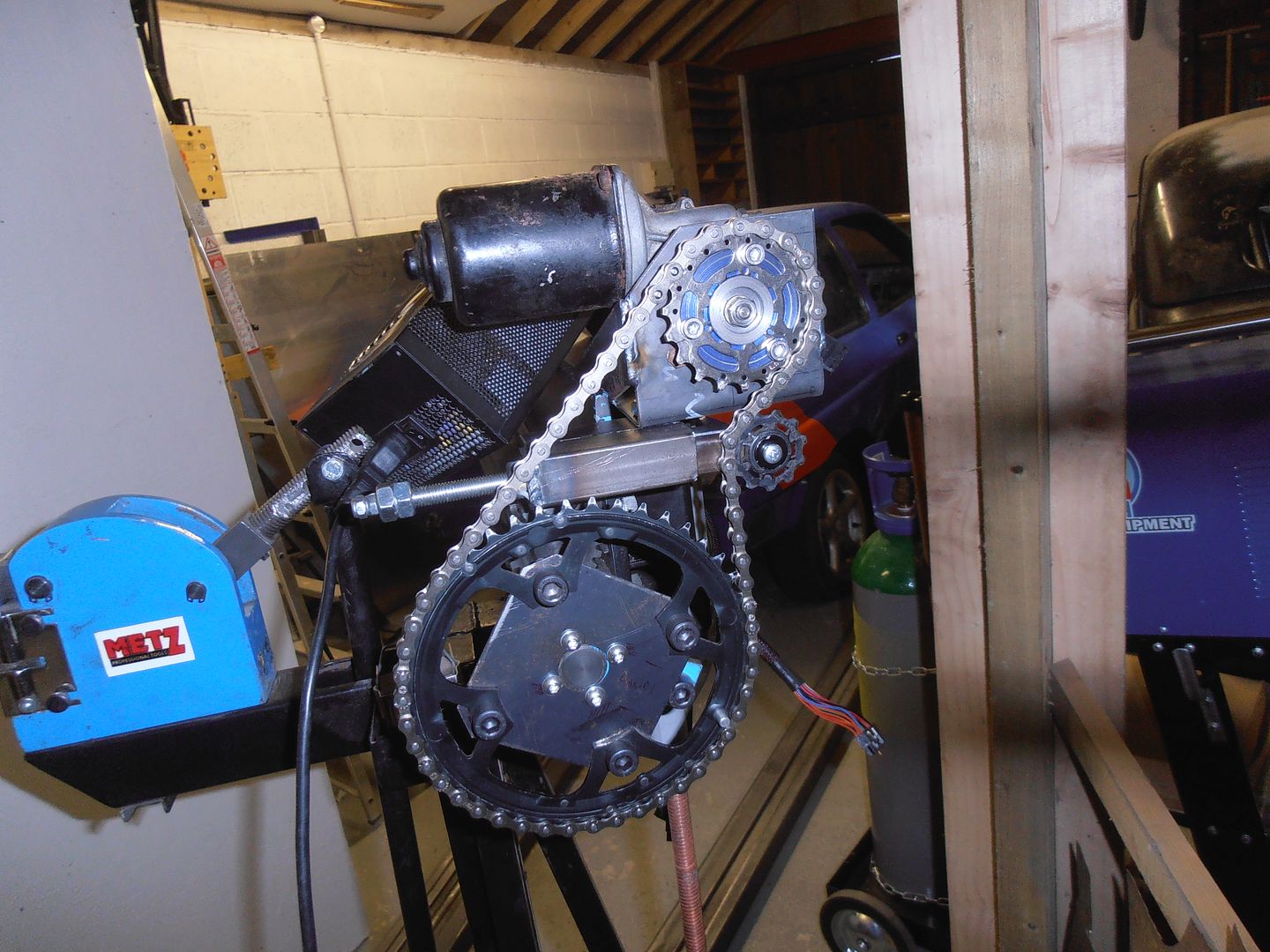 and turn the power on. It worked quite well, and the spring allowed it to float in and out with the slight eccentricity of the mounting bolts, giving a good constant tension in the chain. There are some mods needed though 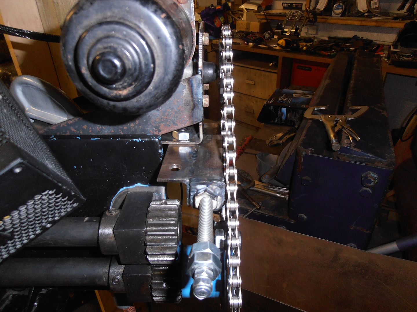 The chain sits very very close to the body, so I need to space the tensioner wheel out slightly, but I need a longer bolt to do this. I also need to re-do the mountings as its too far the wrong way to get more than one bolt in. doh. I also need to properly fix down the drive motor mount as it was all working nicely till i tried doing a deep bead in 1 pass and everything then rotated and the chain popped off. A single g clamp gives a nice pivot point. |
| |
|
|
jonomisfit
Club Retro Rides Member
Posts: 1,789
Club RR Member Number: 49
|
|
|
|
I tweaked the bead roller drive a bit more today. 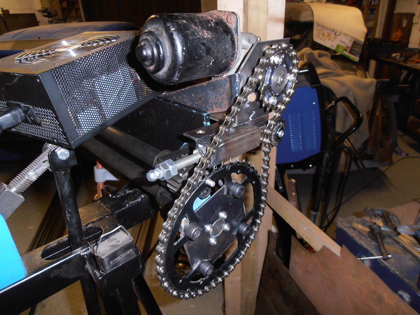 added some fixings 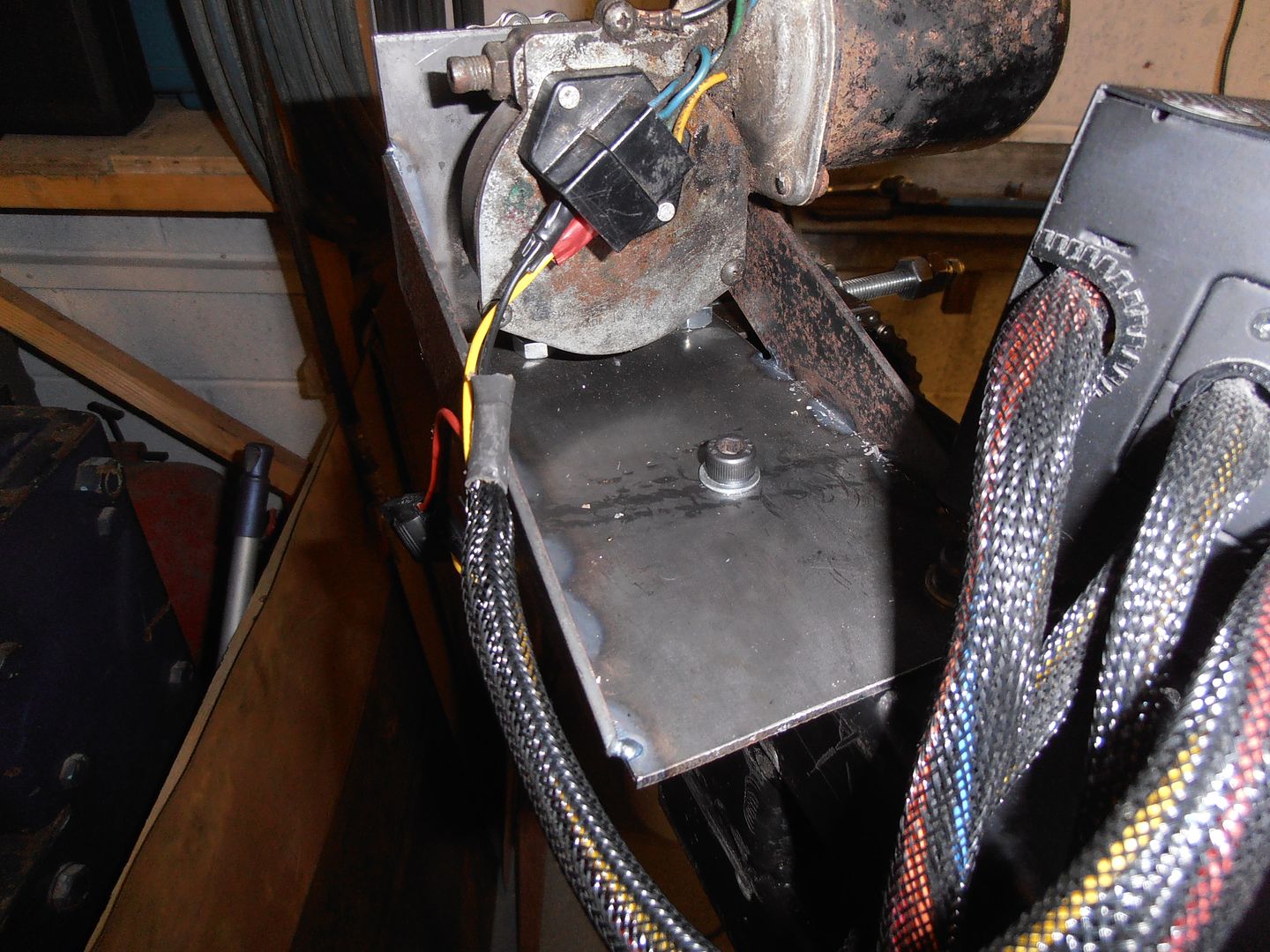 and extended the tensioner mount 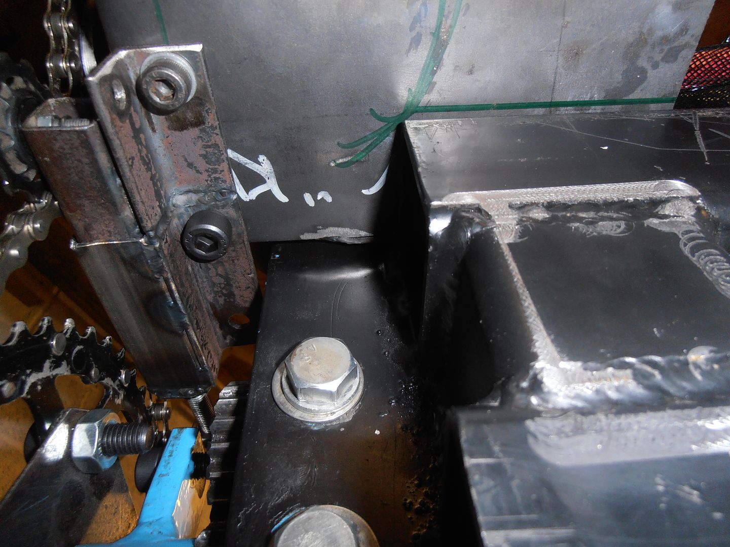 which got it all running nicely. I think i might fit a vertical stiffener under the drive, but will see. Anyway, back to the morris. Where was I. Oh yeah, pedal box 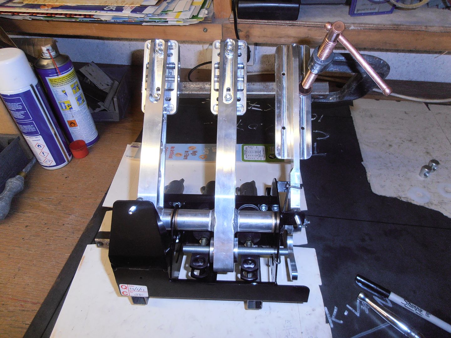 this shows the issue with the push rods. With the clevises screwed in full depth there is still a fair distance from the centre of the clevis to the threaded balance rod. 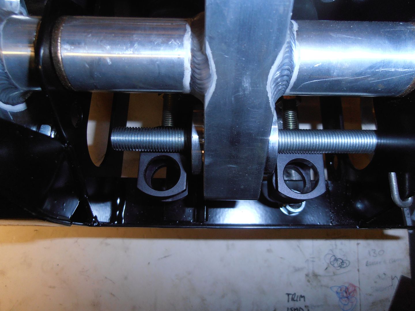 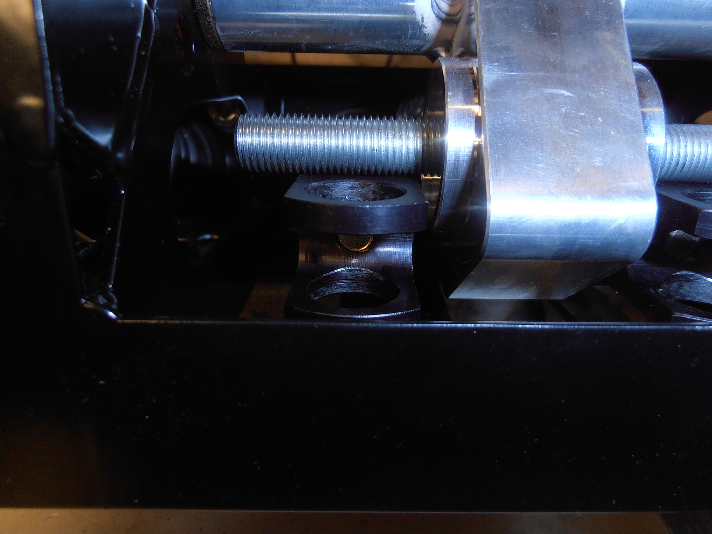 about 15mm 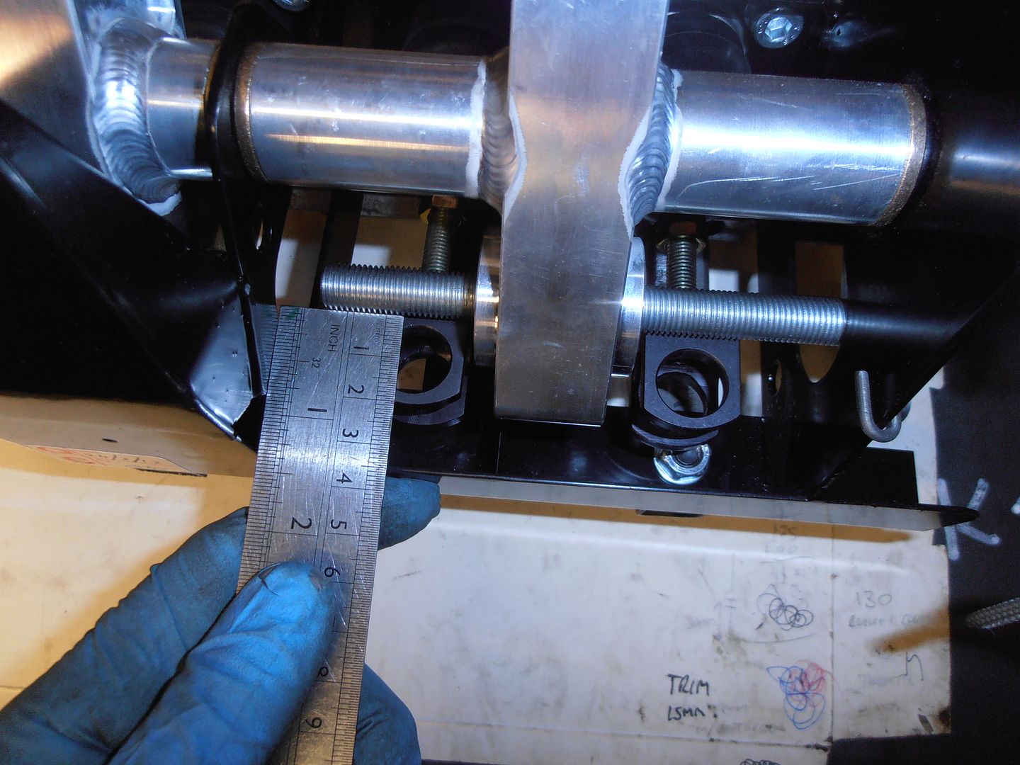 So take out the master cylinders and a bit of trimmage later 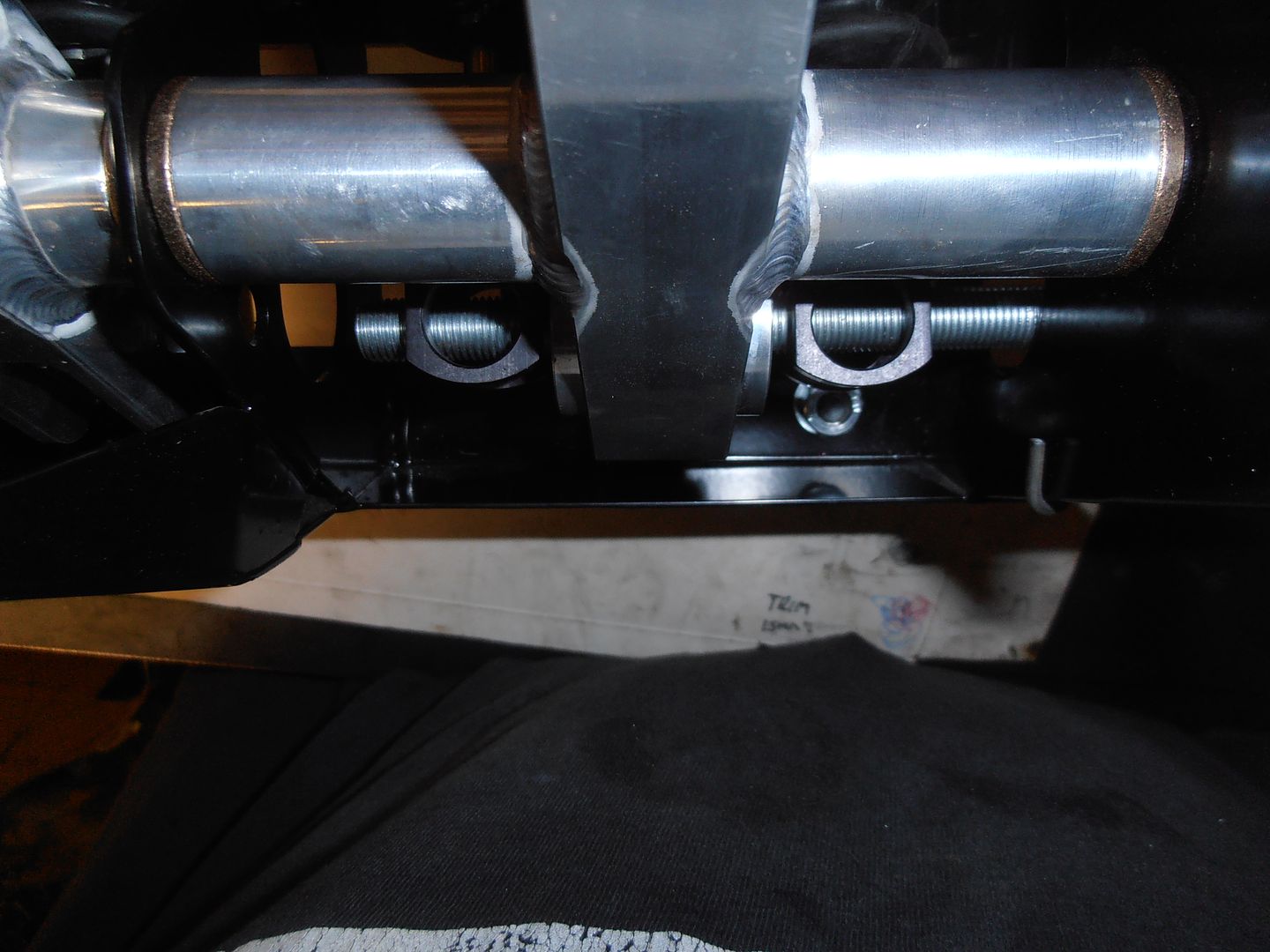 Perfecto, plus have some adjustment in both directions now to get the pedal where i want it. give things a little adjust, and trim the push rod on the clutch and 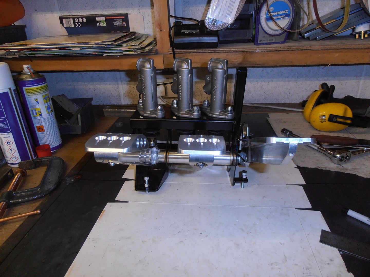 pedals line up without any load. balance bar now sits right as well 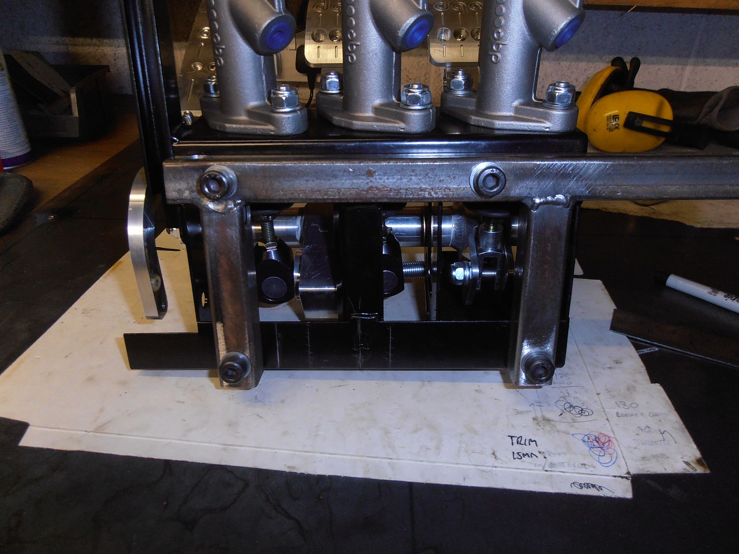 pedals back into the car 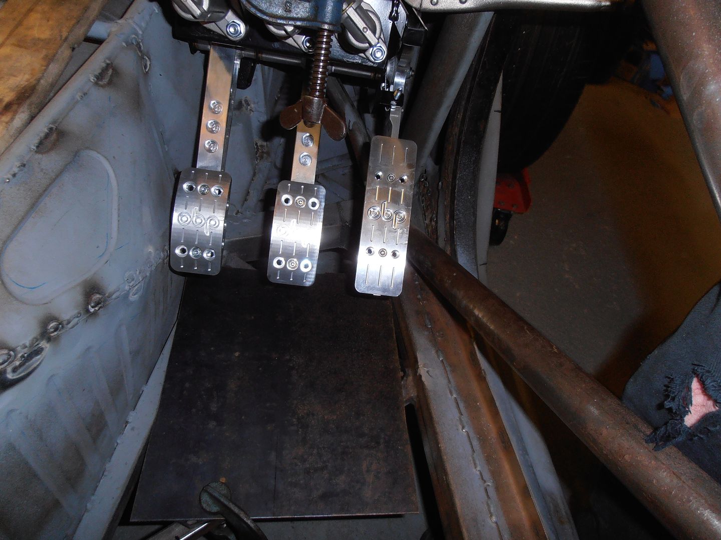 much better 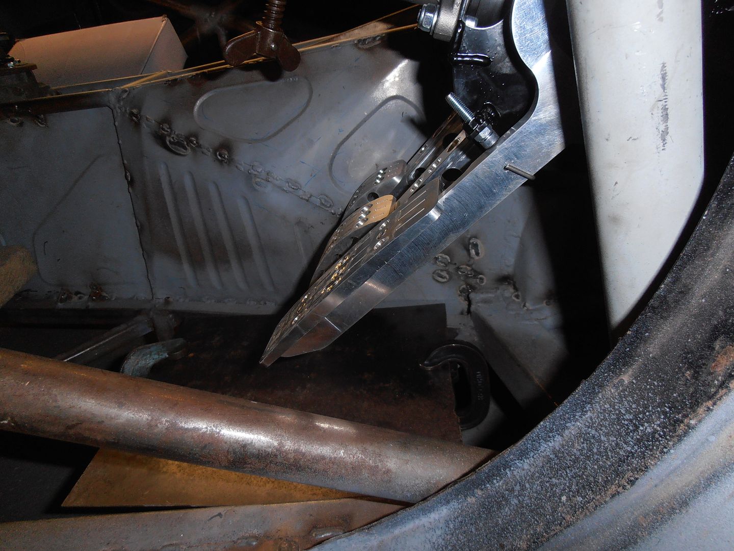 clears nicely on full throttle 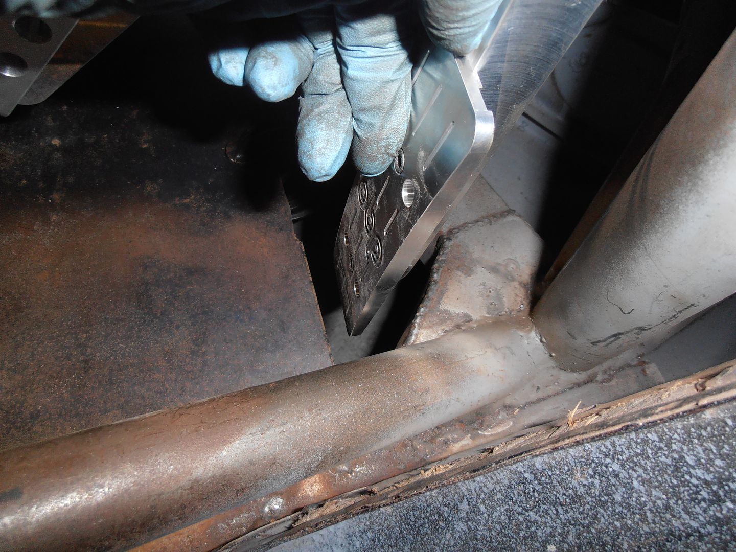 and brakes beyond maximum travel 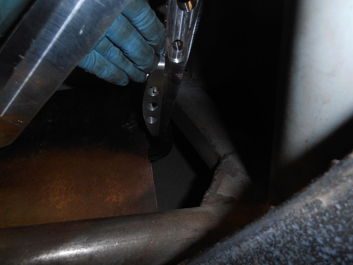 To push it back any further and raise any more, i need to notch out a piece of structure 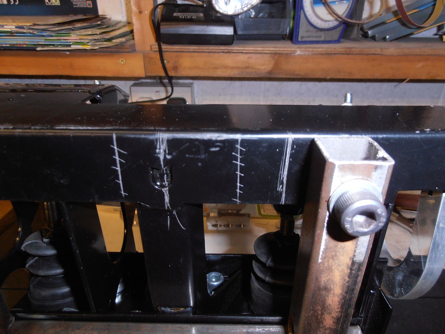 start cleaning back 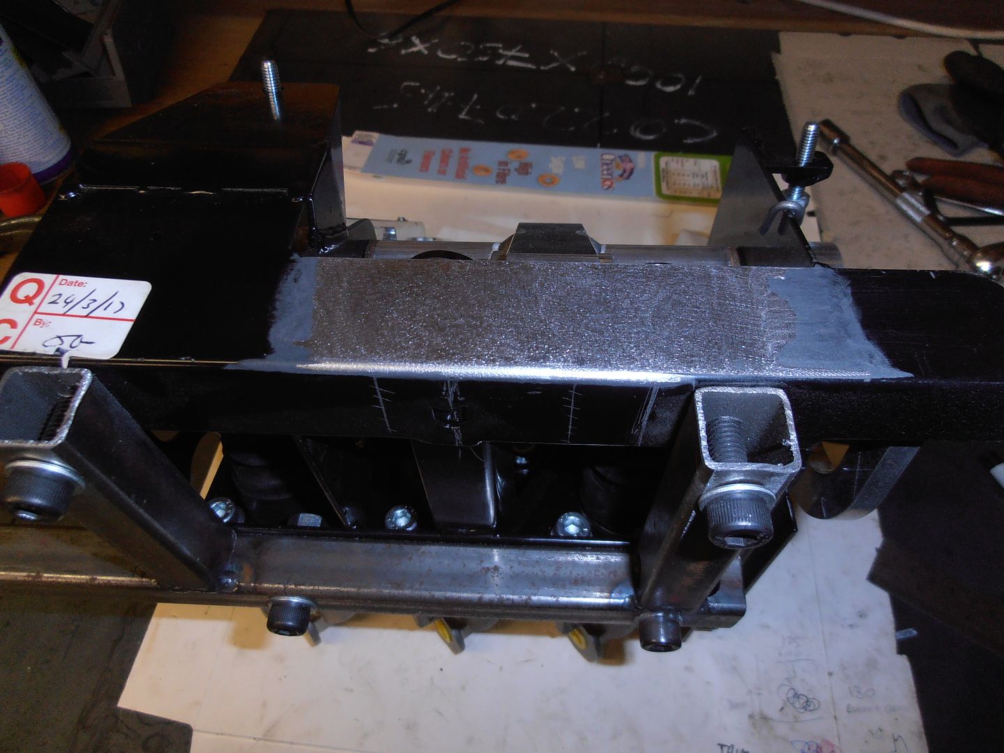 mark out 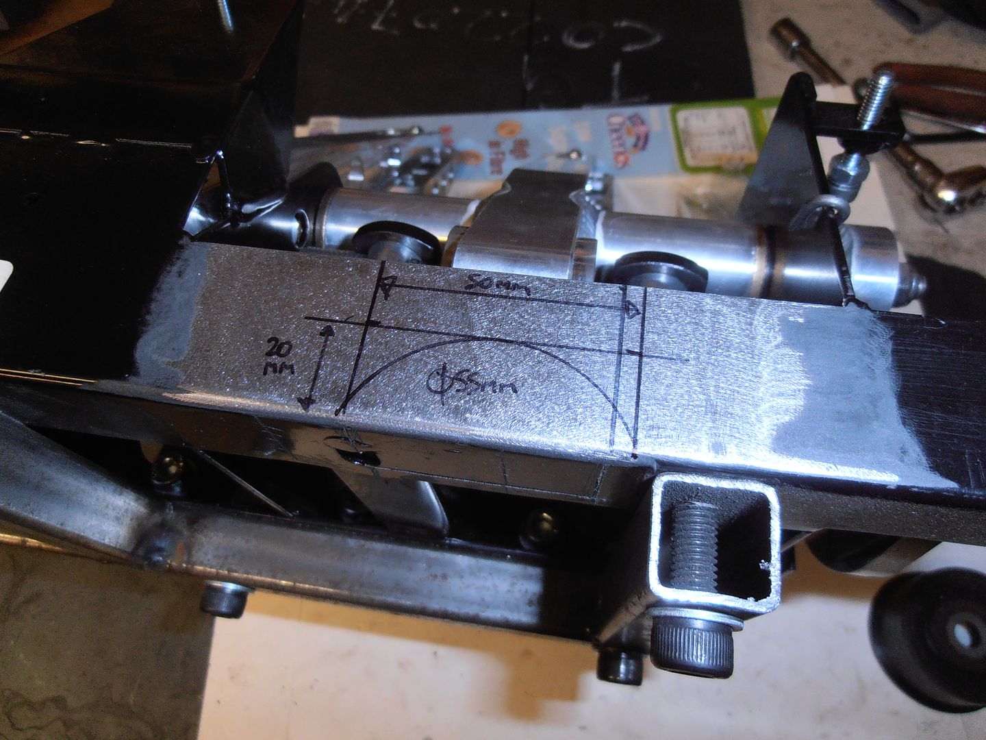 and the other side 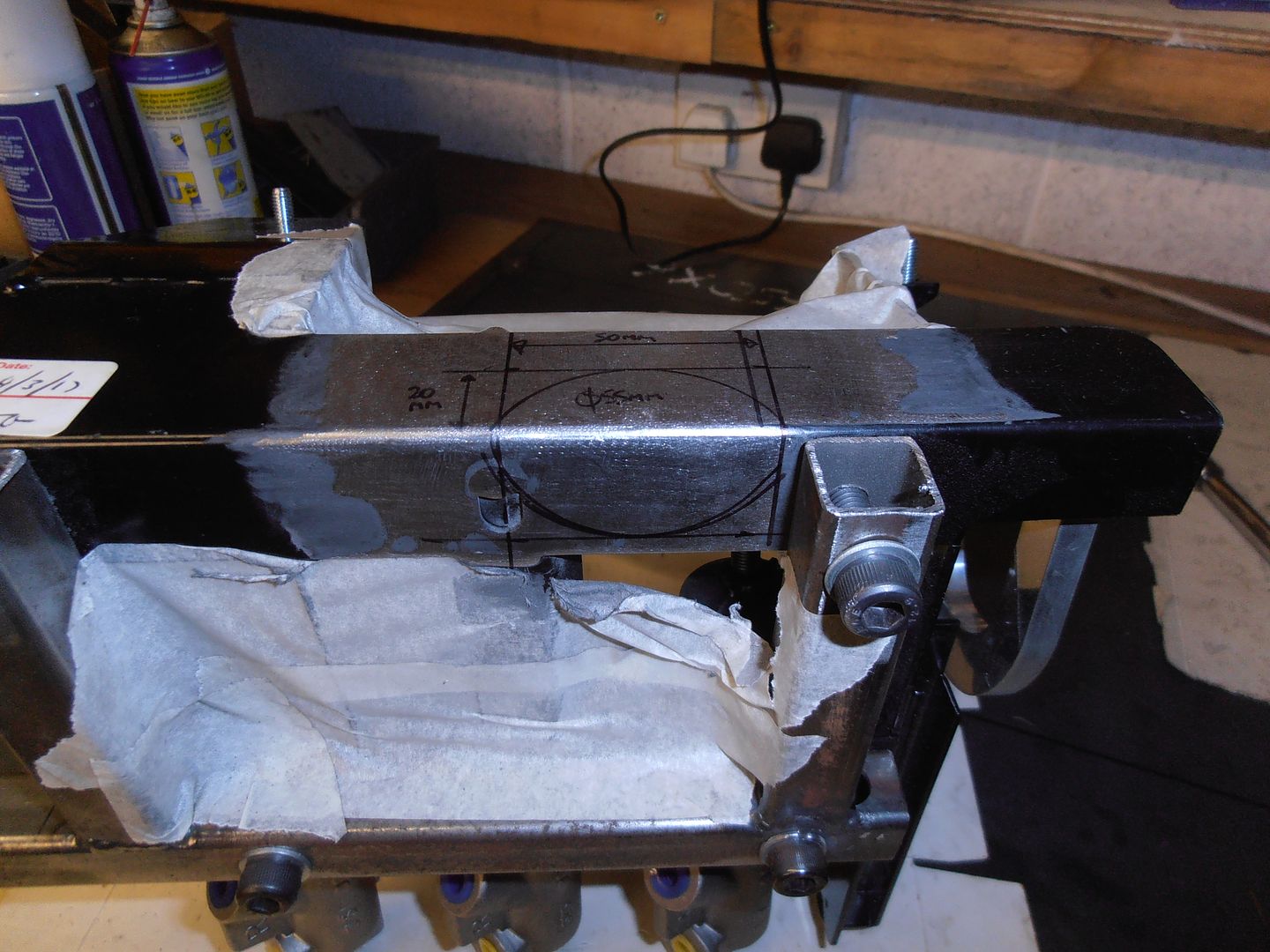 and trim 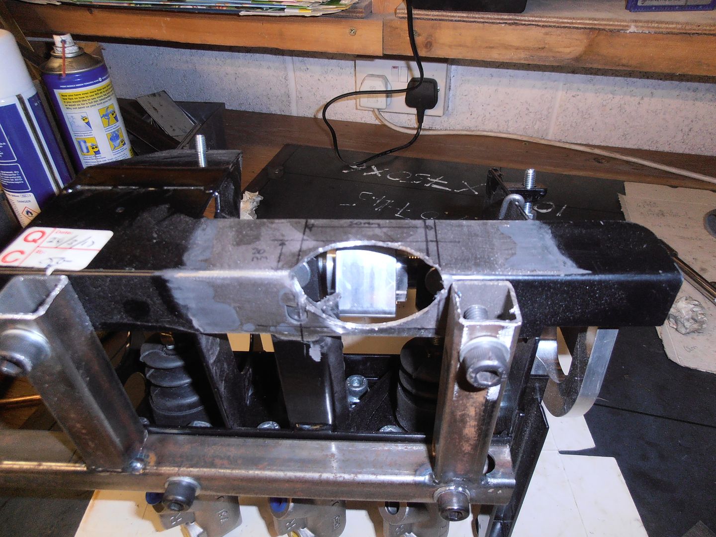 checking how this improves clearance 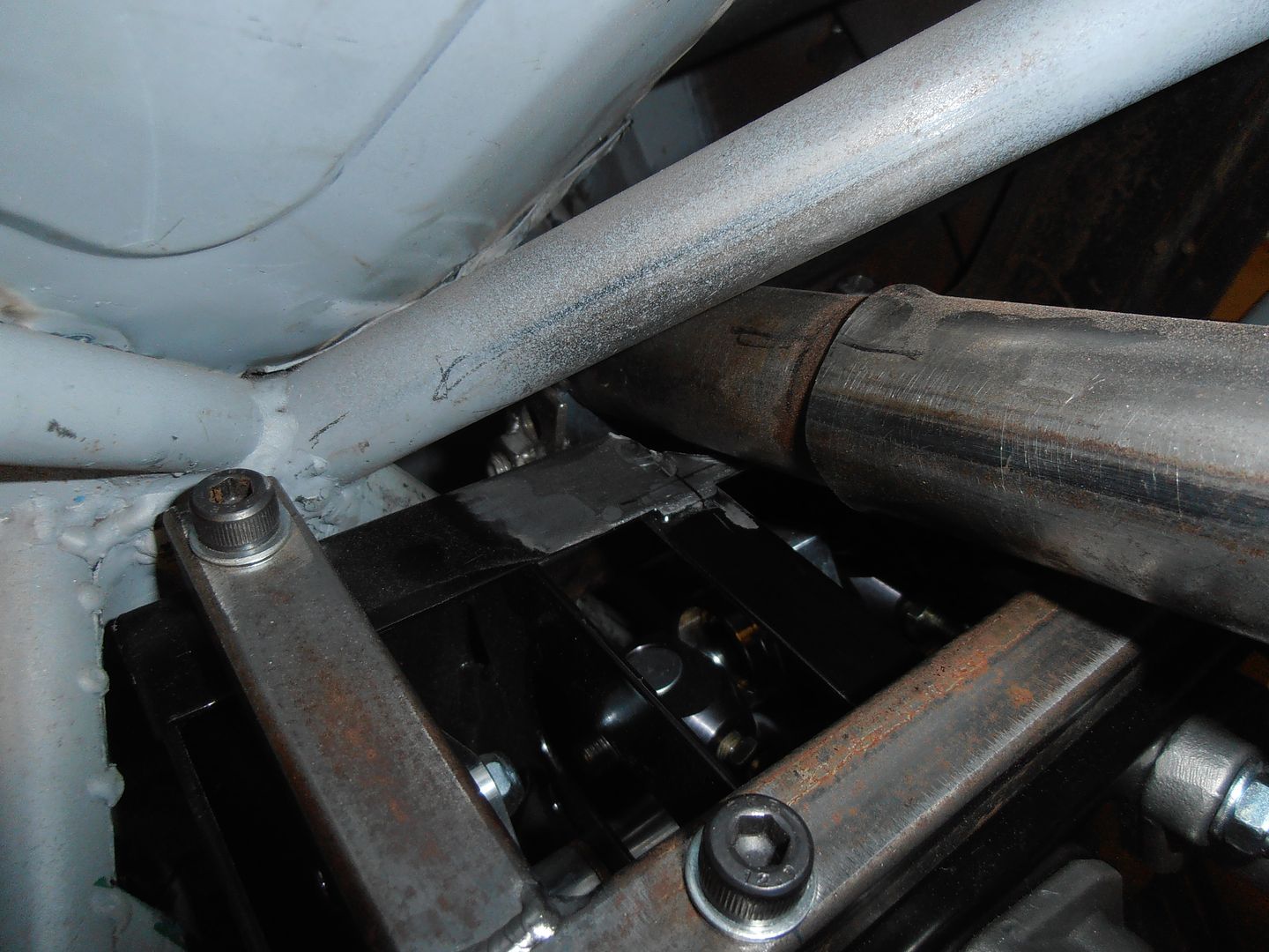 all good. Now fill the hole cut a piece out of a large diam piece of tube I have 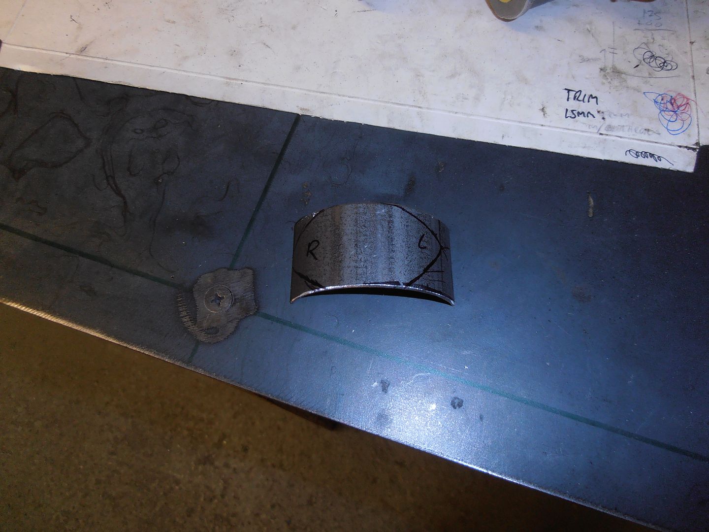 trim 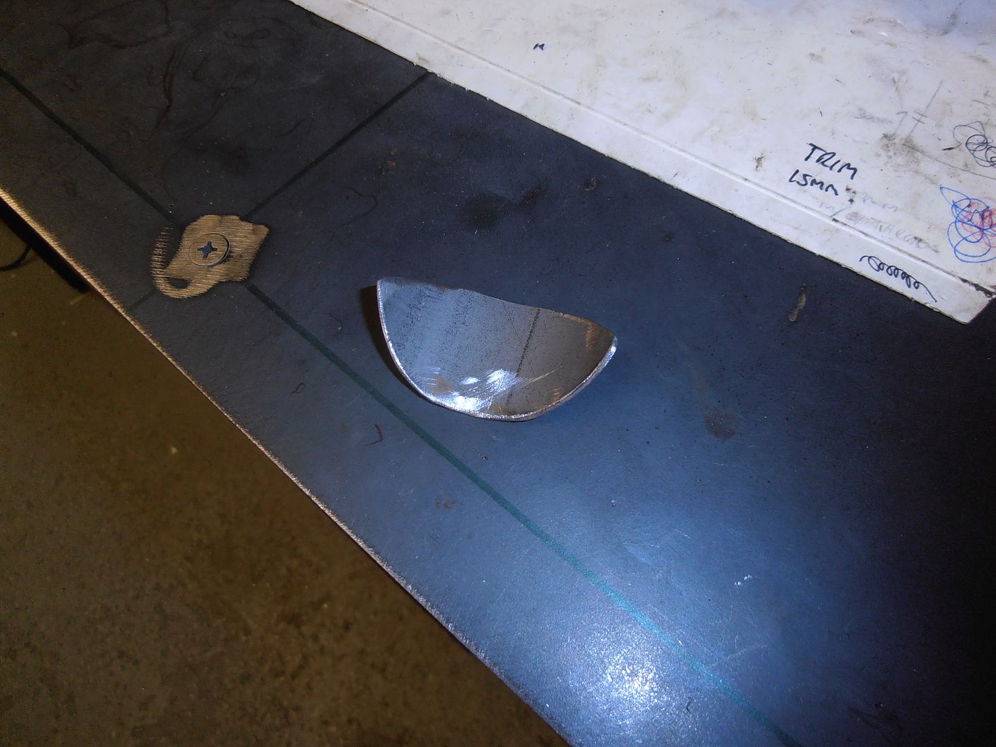 fettle and tack into place 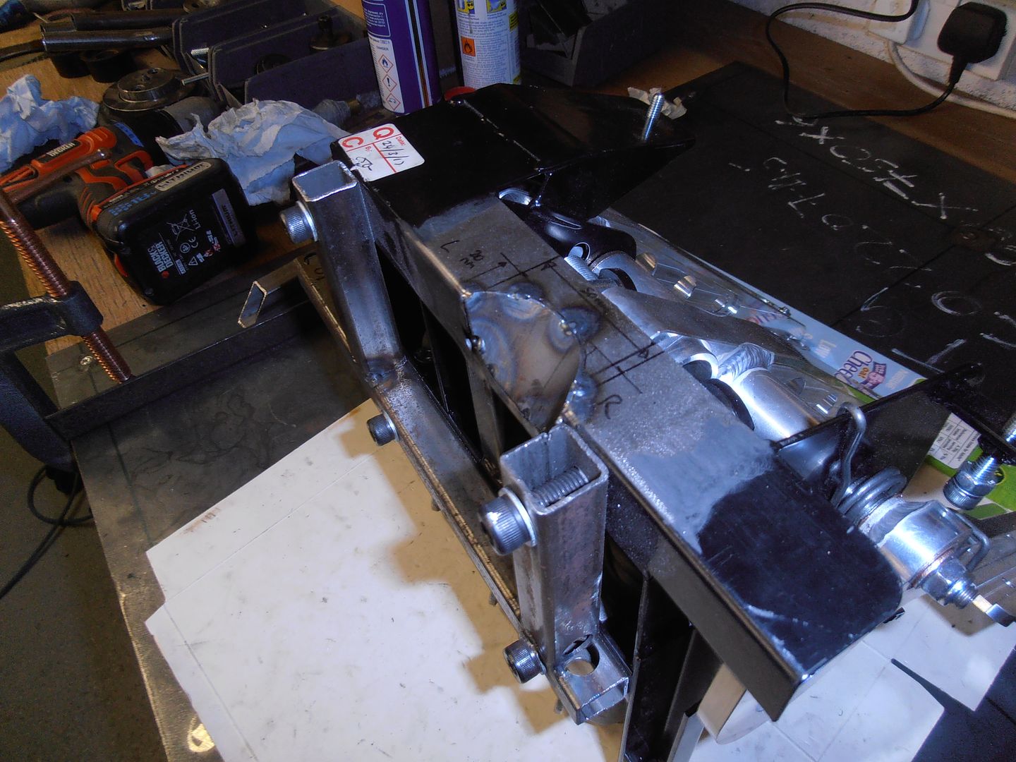 pedal box re-inserted. The notch let it move back by about 20mm and up by about 35mm 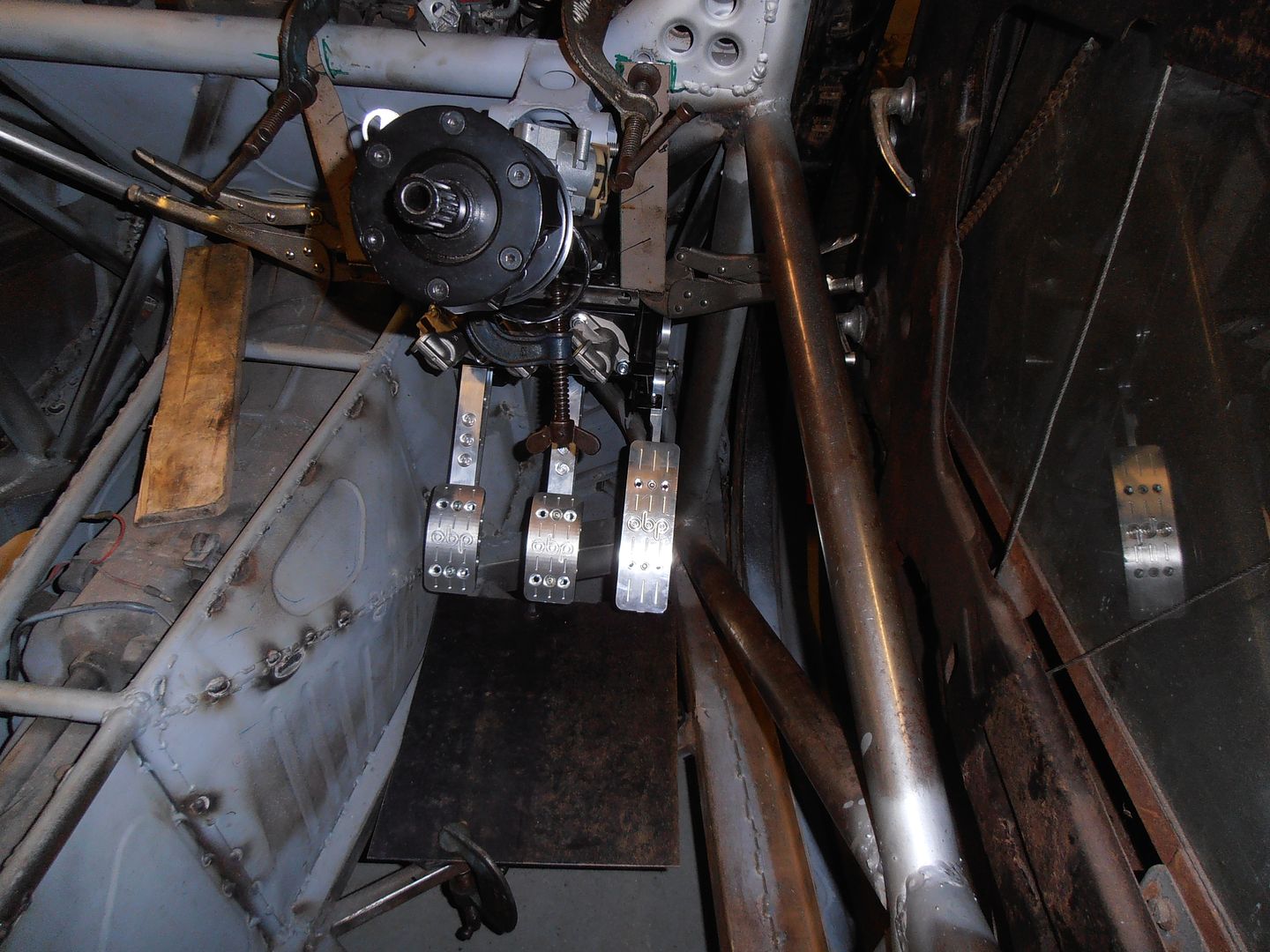 nicely clears, plus where the mount needs to go also lines up with the front bulkhead structure 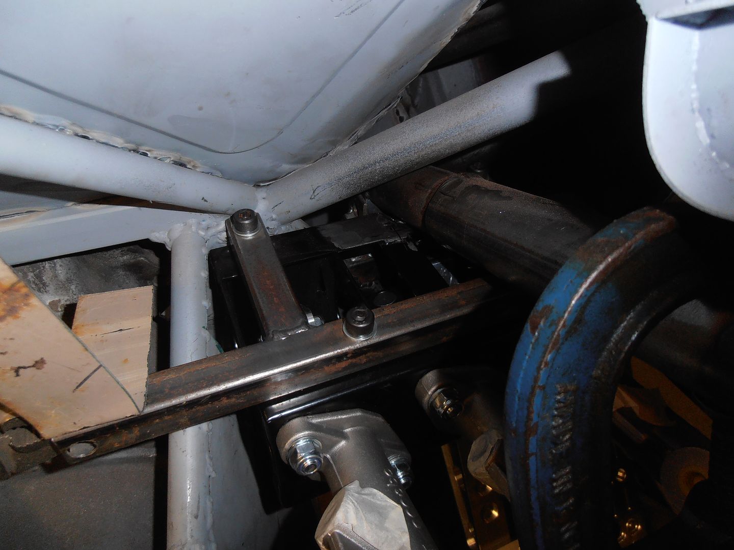 I need to take it out, finish welding, clean it all up and re-paint it. But that can wait for another day. I think the next session will be about mounting the pedal box, but also allowing it to drop out so I can get the column out if I need to. |
| |
|
|
|
|
|
|
|
|
If you're going to bolt it, could you use something like a quick release bolt for a bicycle wheel, but chunkier?
I know how you like over engineering things so it's not a simple spanner job.. :-P
I don't think we've seen enough swaged th ings recently, by the way..
|
| |
|
|
|
|
|
|
|
|
Looking good 😊
Just hope it's not a pain in the arris to bleed those cylinders with them being canted over to the side.Potential for trapped air there.
|
| |
|
|
|
|


