|
|
|
|
|
|
Anyone on here happen to have a Delica Exceed?
I took some electric curtain tracks off a scrap Delica ages ago to one day replace the bits of wire and string I have holding up the curtains in my van. At the time I got them, I gave them a clean up, dabbed the wires across battery and watched the plastic bits shoot back and forth in wonder. And then put them away. For quite a long while.
Now I come to look at them again, I've completely forgotten how they fitted. Can anyone on here help me out by furnishing me with a photo or two of the curtain tracks in situ? Specifically the pair above and below the window on the back door.
Oddly, it looks like one curves into the van but the other curves out. That can't be right can it?
Also, if anyone has a Delica Haynes manual knocking about, can you tell me how are they meant to be wired up? None of the wires I chopped out of the loom matches the colour of any other. Do they go in series or parallel?
Cheers!
|
| |
|
|
|
|
|
|
|
|
|
|
First things first, did you pull them out of an L300 or an L400?
They are both very different arrangements so once we can establish that I might be able to help (a little).
|
| |
|
|
|
|
|
|
|
First things first, did you pull them out of an L300 or an L400? They are both very different arrangements so once we can establish that I might be able to help (a little). Cool. I think it was an L400. It was the later, roundier shape, 4WD, and the difference in the lengths of the tracks I have suggest the tailgate had quite a significant taper to it. Thanks! |
| |
|
|
|
|
|
|
|
Ahh..that's a shame, I know more about the L300 ones I'm afraid  The L400 ones aren't as rare though so there is a bit more knowledge about them if you head over to MDOCUK. I am sure someone on there will have some more info for you. If it had been an L300 then I have the factory wiring diagrams here. I'll dig it out anyway and send it over to you, might not be of any use, but then you never know? |
| |
|
|
|
|
|
|
|
|
Thanks very much MM. The wiring diagrams could well be useful.
The ones I have are a bit of an unusual set up. There are no cables or pulleys. The tracks themselves are the motors. There's a long linear segmented commutator down the whole length of each one and the sledge has two coils and four tiny brushes. That, and the mismatched wiring colours has got me thinking I should have dug about for an ECU or something as hooking them directly across the battery might ruin them.
Is the L300 set up is anything like that?
Studying some photos on the web, I think I've sussed out why one of them bows into the van. It's to curve around the high level brake light. Could just leave it as is but I wonder if I can straighten it out? It's aluminium extrusion with a bit of internal geometry.
|
| |
|
|
|
|
|
|
|
I've just had a check and my manuals don't cover the electric curtains  Over 1,000 pages of wiring diagrams and not even a mention of the curtains. Sorry Dude. I might, however, have something very rare and very cool you'' probably be interested in though. Back in a mo...... |
| |
|
|
|
|
|
|
|
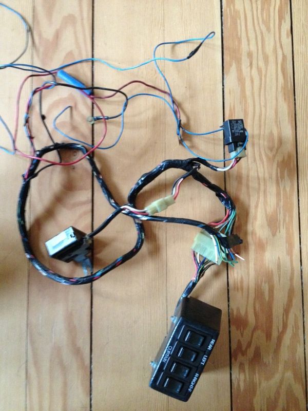
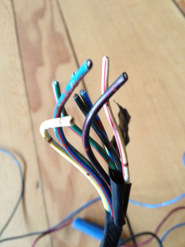
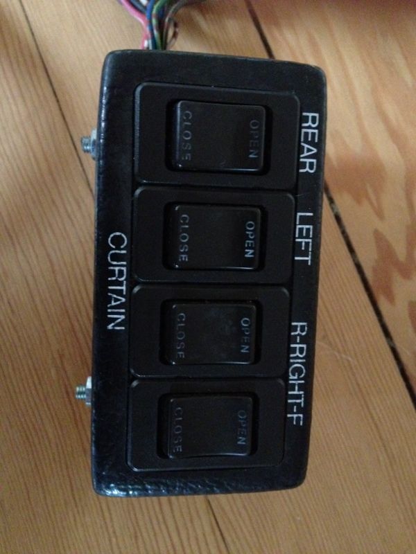
Would this interest you at all?  Control unit for Delica electric curtains? About as rare an item as they come (I've only ever seen this in two L300 Delicas....out of about 300+ I've seen/worked on/owned) The wiring was cut off when I found it but the main 'live' lead is there along with the accessory wire and earth, so the whole lot should be easy to power. It's then a case of checking the output from each of these wires and connecting it to the appropriate set of curtain tracks.  The relay and control ECU is there....so with some checking/testing should work perfectly with your curtain tracks. And as the added bonus, you get to mount this somewhere:  I've been hiding it away for years but don't think I'll ever get to use it as planned, so if you're interested I'd certainly consider selling it.  |
| |
|
|
|
|
|
|
|
That's awesome and thanks very much for checking out the wiring diagrams. Just checked the wire colours on mine. I have plain yellow and blue with yellow tracer on one and yellow with white tracer and silver dots and plain yellow with silver dots on the other.  I don't think it quite matches what's on your control unit, which is a real shame. What were you saving it for originally, if you don't mind me asking? Here's how I guess the tracks were mounted relative to each other (looking in from outside the back window).  And this is the linear motor thing in one of them.  |
| |
|
|
|
|
|
|
|
|
Hmm, Looking at that, there are only two wires going to each track? If so, I bet they feed power down the central commutator to a little motor in that end "carriage" just like a scalextric. It should move with power applied to it, and reverse direction when you swap polarity.
If there's only two wires per track then there really isn't any other practical way that it could have been wired.
Each unit will be wired in parallel (in series would be a very strange way of doing things, and would result in very unpredictable movement)
Stick 12v on them and they should move one way or the other. If you want to get them going with an electric window switch type affair, just wire them as you would electric windows. You can get universal switches off ebay for not a lot which come with wiring diagrams!)
Any ECU in the system would probably just be to detect when the things hit the endstops (current spike) and cut them off.
|
| |
|
|
|
|
|
|
|
That's what I thought too Cobblers. However, it shoots really violently from one side to the other on 12V. Here's what the sledge looks like inside. It really is a motor unrolled flat. The two coils have a pair of brushes each on springy strips. They are 8.2 ohms each, which means at least 17.5W per coil if held against the end stops. I don't think they would last long if something got jammed.  It was a bit difficult to get a good picture of, but here's the commutator - a great long strip of flexi PCB material the length of the track. I think there are bus bars either side and the segments connect alternately to one or the other.  And opposing that is the magnetic strip, which looks like a strip of fridge magnet material.  I think the spacing of the coils is about 2½ segments so there is always some pull on the armature. Reversing the wires does shoot the sledge in the opposite direction. |
| |
|
|
|
|
|
|
|
|
Hmm, Thats dead snazzy, I like it!
17w is definitely a lot of power to sink into that little coil if it's stopped, but I can't imagine they would wire the two rails in series, otherwise the one with the most drag would end up receiving the least torque.
Do you think they would move a bit more acceptably if they had the weight of the curtains on them? Then you just need to worry about making sure they don't end up dead up against the end stops boiling the coils over.
Have you got a method of measuring the current drawn when they are moving vs the current when they hit the end stop?
|
| |
|
|
|
|
|
|
|
|
No, it happens too quickly for my meter to register it properly. I think it's somewhere between 0.5A and 1A though, vs. 1.15A when stalled. (There's probably a bit of resistance in the connections somewhere).
I don't think there's enough of a difference to reliably detect if it's stalled that way. Perhaps they just had some sort of time-out in the relay. I didn't get the curtains with the rails and haven't made the new ones yet. (Waiting on some offcuts of the special tape you have to stitch in to get hem to bunch up properly.) I guess it will slow them down a bit though.
|
| |
|
|
|
|
|
|
|
|
Yeah, a timeout is probably the easiest way. Even with 17 odd watts going into the coils, they aren't going to melt too quickly - once you get them fitted, perhaps just measure how long they take to open/close, add 20% or so and rig something (555, mosfet and a relay probably) up to cut the power after that long. Or just don't hold the switch down for ages.
|
| |
|
|


 [*]
[*] [*]
[*]


