|
|
|
Jan 21, 2012 21:39:45 GMT
|
|
Ok, need your help. I'm sure this is simple, but it seems not simple enough for me....
I am using an LED toggle switch as a manual override for the electric fan.
I have so far got the switch wired up correctly to switch the fan on and off independent of the thermostat control.
Where I am struggling is getting the switch to light up when it is switched on.
So far, the switch light comes on when the switch is in the 'Off' position - the exact opposite of what I want.
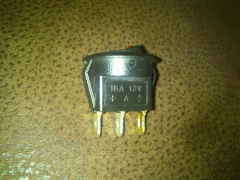
There are 3 terminals on the back of the switch.
I am currently connecting 1 to earth, 1 to the fuse box and the last to the relay.
Where am I going wrong?
|
| |
Last Edit: Jan 21, 2012 22:17:04 GMT by alolympic
|
|
|
|
john61
Part of things
  just give in to it
Posts: 32
|
|
Jan 21, 2012 23:43:09 GMT
|
power in and power out to relay wires  swop em around ?? are there any symbols/numbers on the contacts on the swithch ?? 30 or 15=fusebox 31= earth 86=relay didnt the switch come with wiring diagram  |
| |
Porsche 911 SC
VW T25 SYNCRO
BSA C 15
HONDA CBR 1000
|
|
|
|
|
Jan 22, 2012 12:24:37 GMT
|
|
Are the pins labelled? There should be one to earth, which is self explanatory. One to 12v and one that says something like 'accessory'. I normally end up mixing up the power and accessory ones initially.. which it sounds like what you have done?
EDIT: I found a pic to verify what I said but it won't post up..
|
| |
Last Edit: Jan 22, 2012 12:27:56 GMT by ben711200
...proper medallion man chest wig motoring. |
|
|
|
|
Jan 22, 2012 21:47:39 GMT
|
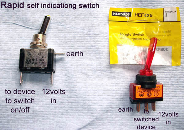
I did the same, for the same purpose. I'm curse word at electrics but this sorted me out, I used the type at left. HTH-  Pic courtesy of S2 Landy club |
| |
'66 Amazon <-> '94 LS400 <-> '86 Suzuki 1135 EFE
|
|
mk2cossie
Club Retro Rides Member
Posts: 3,062  Club RR Member Number: 77
|
|
Jan 22, 2012 22:41:16 GMT
|
|
is the switch earthing the component, or feeding it?
some of the 3pin illuminating switches will only illuminate if connected to energise something instead of earthing it ;D
|
| |
|
|
|
|
|
Jan 23, 2012 10:54:18 GMT
|
I did the same, for the same purpose. I'm curse word at electrics but this sorted me out, I used the type at left. HTH-  Pic courtesy of S2 Landy club Thanks. That is exactly what I have tried, but the LED is only On when the switch is off. I think the problem may be the relay side. The switch works, but because the switch is connected to the relay, and in effect the circuit is complete even when the switch is off? Anyway, not critical, it is working, I have just wired it so the LED doesn't come on. |
| |
|
|
MiataMark
Club Retro Rides Member
Posts: 2,971
Club RR Member Number: 29
|
|
Jan 23, 2012 11:04:17 GMT
|
|
When you say relay, is this the relay already installed as part of the elctric fan kit, or a new "over ride" relay?
What you should have is,
12v - switch - relay (coil) - earth
|
| |
1990 Mazda MX-52012 BMW 118i (170bhp) - white appliance 2011 Land Rover Freelander 2 TD4 2003 Land Rover Discovery II TD52007 Alfa Romeo 159 Sportwagon JTDm
|
|
|
|
|
Jan 23, 2012 12:09:02 GMT
|
When you say relay, is this the relay already installed as part of the elctric fan kit, or a new "over ride" relay? What you should have is, 12v - switch - relay (coil) - earth It's a new relay that I have installed. I have basically copied this guys set up - there is a wiring diagram at the bottom of the page - www.trdrivers.com/fan.htmlThe only difference with mine is that I am using an LED toggle switch, instead of a standard one. So, I have a separate Fan On light - which illuminates whenever the fan is on (working fine). I want the LED light on the toggle switch to be illuminated only when the manual override is on. This is the problem. |
| |
|
|
MiataMark
Club Retro Rides Member
Posts: 2,971
Club RR Member Number: 29
|
|
Jan 23, 2012 12:50:30 GMT
|
What you have then is this, the linked diagram but with a bit more detail and your LED switch,  Try swapping the wires round on the switch. I would think it would also be a good idea to include an indicator to show when the fan is running as in the original diagram. Relay pin-outs from Vehicle Wiring Products catalogue, well worth getting if only as a reference. Hope this helps. |
| |
1990 Mazda MX-52012 BMW 118i (170bhp) - white appliance 2011 Land Rover Freelander 2 TD4 2003 Land Rover Discovery II TD52007 Alfa Romeo 159 Sportwagon JTDm
|
|
|
|
|
Jan 23, 2012 13:04:51 GMT
|
What you have then is this, the linked diagram but with a bit more detail and your LED switch,  Try swapping the wires round on the switch. I would think it would also be a good idea to include an indicator to show when the fan is running as in the original diagram. Relay pin-outs from Vehicle Wiring Products catalogue, well worth getting if only as a reference. Hope this helps. I ahve tried the wires in every combination on the switch, I still can't get the correct result. I already have the 'fan on' light as mentioned above. That is working fine. Thanks, still at a loss though. It is not which wires are going to which terminal on the switch, more, am I connecting the switch to the correct thing. |
| |
|
|
|
|
MiataMark
Club Retro Rides Member
Posts: 2,971
Club RR Member Number: 29
|
|
Jan 23, 2012 13:18:38 GMT
|
|
The only explanation is that the switch is reversed, i.e. LED before the switch. TBH using the LED switch to switch to ground probably isn't the best route, as there will be voltage from the relay coil.
Use a non illuminated switch, or a parallel relay for the always on function with the LED switch before the relay.
Not that this explains why swapping connections doesn't at least change things....
Mark
|
| |
1990 Mazda MX-52012 BMW 118i (170bhp) - white appliance 2011 Land Rover Freelander 2 TD4 2003 Land Rover Discovery II TD52007 Alfa Romeo 159 Sportwagon JTDm
|
|
|
|
|
Jan 23, 2012 13:27:06 GMT
|
The only explanation is that the switch is reversed, I.e. LED before the switch. TBH using the LED switch to switch to ground probably isn't the best route, as there will be voltage from the relay coil. Use a non illuminated switch, or a parallel relay for the always on function with the LED switch before the relay. Not that this explains why swapping connections doesn't at least change things.... Mark Cool, thanks. Swapping connections DOES change things, I am just saying that whatever combination of connections to the switch, I don't get the right result. I'm still confused I'm sorry.......I give up |
| |
|
|
MiataMark
Club Retro Rides Member
Posts: 2,971
Club RR Member Number: 29
|
|
Jan 23, 2012 13:52:09 GMT
|
|
Without being able to actually tinker wityh it I'm lost as well.
If it was me I'd swap it for a non LED switch.
BTW, really like your car one of my favourites on the forum. I'm a Triumph fan was brought up with them, my dad had a Herald and a 1300TC. I had a 13/60 convertible as a student and a Spitfire as a project car (which went my my daughter was born).
Mark
|
| |
Last Edit: Jan 23, 2012 13:54:21 GMT by MiataMark
1990 Mazda MX-52012 BMW 118i (170bhp) - white appliance 2011 Land Rover Freelander 2 TD4 2003 Land Rover Discovery II TD52007 Alfa Romeo 159 Sportwagon JTDm
|
|
|
|
|
Jan 23, 2012 14:09:10 GMT
|
I'm wiring my fan next week Al, I have exactly the same switch as you, I'll see what happens when I attempt it. Probably a big fire. Hold on a sec, does the light stay on when the fan is on? I think what you've got is the feed from the fuse box is keeping the light permanently on. I'm tempted to put money on that if you wire both the + terminals off the relay, ignore the fusebox, the light will only come on when the relay switches... I've just tested mine out, both the + terminals seem to turn the light on.   |
| |
|
|
MiataMark
Club Retro Rides Member
Posts: 2,971
Club RR Member Number: 29
|
|
Jan 23, 2012 15:21:22 GMT
|
Using this switch to switch the earth will give incorrect results. When the switch is off the LED will still get voltage from the relay, when it is closed then you're bypassing the LED. You really need a doube pole switch with a seperate imdicator. Or try this circuit;  I'm guessing that the TCU is just a relay, also this way the LED will illuminate when the fan is on automatically, so you only need one indicator. Try at your own risk..... |
| |
1990 Mazda MX-52012 BMW 118i (170bhp) - white appliance 2011 Land Rover Freelander 2 TD4 2003 Land Rover Discovery II TD52007 Alfa Romeo 159 Sportwagon JTDm
|
|
RobinJI
Posted a lot
   "Driven by the irony that only being shackled to the road could ever I be free"
Posts: 2,995
|
|
Jan 23, 2012 22:20:01 GMT
|
|
As Garra says, the problem's that the switch is after the relay. There's a couple of ways round this depending on what you'll find easiest.
The trouble is that in your current set-up, (assuming it's like the first diagram garra posted), the only resistance in the relays circuit is the relay it's self, with the LED placed on a parallel circuit taking it's feed from after the relay. With no resistance after it the voltage after the relay is 0v, meaning the LED's getting nothing to it, it's effectively connected to an earth at both ends.
Ideally, you want to place the switch before the relay, that way it's taking its feed from the full 12v that's between the battery and the first point of resistance (the relay), but when the switch is off there's no power for the relay when the thermostat tries to earth it, so you'd have to change the circuit to match garra's 2nd diagram.
One way around this would be to leave it wired as the first diagram, but place a resistor after the switch, before the relays earth (but not the switch's LED's earth, which should be separate). This will give a voltage between the relay and your new resistor, so your feed to the LED will actually have some voltage to take. The trouble here is that the LED won't get it's full 12v, so may appear dim. I'm not 100% what size resistor you'd want for this.
Another way around doing this would be to wire the output from the relay to either of the positive terminals on the switch, and then the earth on the switch to earth, leaving the 3rd terminal unused. This would place the LED in the relay circuit, rather than on its own separate circuit. Again it won't get a full 12v, so might be a bit dimmer.
When you wired it so that the LED came on when in the off position, I'm guessing you had the an earth going to the '+12v in' terminal and the 'earth' terminal, the feed from the relay wired to the 'to switched device'. When it was like that, was the fan on permanently, regardless of the switch, or did it work as it should? If it was working as it should, then in theory, my 2nd option wouldn't work because the LED part of the switch is causing too much resistance and stopping the relay operating. If the fan was permanently on, then my second suggestion should work fine.
|
| |
Last Edit: Jan 23, 2012 23:20:54 GMT by RobinJI
|
|
|
|
|
Jan 24, 2012 17:56:28 GMT
|
|
Thanks for the responses guys. I'm sure the right way forward is in there somewhere, I just can't work it out.
So, to confirm, what is achievable by swapping the wires to the different switch terminals -
1) The LED on the switch alights when the switch is off. The switch can turn the fan on or off fine.
2) The LED on the switch does not alight when the switch is in either position. The switch can turn the fan or off fine.
In both situations, the thermostat also controls the fan fine.
In both situations the independent 'fan on' dashboard light comes on only when the fan is on as intended.
|
| |
Last Edit: Jan 24, 2012 17:57:17 GMT by alolympic
|
|
|
|
|
Jan 24, 2012 18:05:40 GMT
|
|
Do you just have the relay wired up incorrectly? Using the "normally closed" contact instead of tyhe "normally open"
Pin 86a instead of pin 86.
This would have the effect of turning the fan off when the switch is on.
|
| |
Last Edit: Jan 24, 2012 18:11:10 GMT by cobblers
|
|
|
|
|
Jan 24, 2012 21:41:10 GMT
|
Do you just have the relay wired up incorrectly? Using the "normally closed" contact instead of tyhe "normally open" Pin 86a instead of pin 86. This would have the effect of turning the fan off when the switch is on. That actually makes a lot of sense! I have the switch, and the thermostat both connected to 85 though. It is a 4 pin relay, so in effect, I don't have an 87A. Exactly as the wiring diagram at the bottom of this link www.trdrivers.com/fan.html |
| |
|
|
RobinJI
Posted a lot
   "Driven by the irony that only being shackled to the road could ever I be free"
Posts: 2,995
|
|
Jan 24, 2012 23:13:38 GMT
|
] 1) The LED on the switch alights when the switch is off. The switch can turn the fan on or off fine.] If that's the case, then the LED in the switch must have a resistor built into it, to reduce the current to a level that the LED can handle. (as it's designed to be put directly between a live and earth). When it's in the off possition, there's a circuit but it's through the LED and it's resistor, so it lights up, but the resistor is limiting the current too much, and there's not enough to operate the relay. When you switch to the on position, there's a direct route to earth, so the relay gets a high enough current, but there's no voltage left to light the LED, because it's earthed on both sides now. The only real way around it is to do what garra's suggested, and follow the 2nd circuit diagram he's posted, which should work fine. You could try my 2nd suggestion, of a resistor between the switch and the ground, but it'd take some playing around with different resistor sizes (unless you can get a few values for the relay), and chances are the light would be very dim anyway. |
| |
|
|
|
|


 swop em around ?? are there any symbols/numbers on the contacts on the swithch ??


