I posted something on here a while back about testing lambda sensors and the best way to do it with an oscilloscope. Well I had a few hours to kill down the workshop today so I thought i'd hook my scope up to the volvo and capture a few waveforms. Now, not a lot of people are familiar with using scopes to diagnose faults, but with injection and engine managment becoming more common on our sort of cars it wont be long before a scope will be a must have tool for anyone who wants to be able to diagnose and repair their own cars.
They're not exactly expensive either, you can get a simple hand held single channel velman scope from maplins for less than 100 notes. Work out how much you'll save not having to replace MAF sensors, plugs, leads, coils etc to chase a random fault and you can soon see its money well spent.
Anyway, on with the show. There are two types of lambda sensor, zirconia and titania. Zirconia are the most common, also known as narrow band because they operate between 200 and 800 mV (more on that later). The titania type use a much wider voltage scale, around 0 to 5 volts and they require a seperate power supply.
We'll concentrate on zirconia sensors for now because they are more common and they are the type fitted in my car.
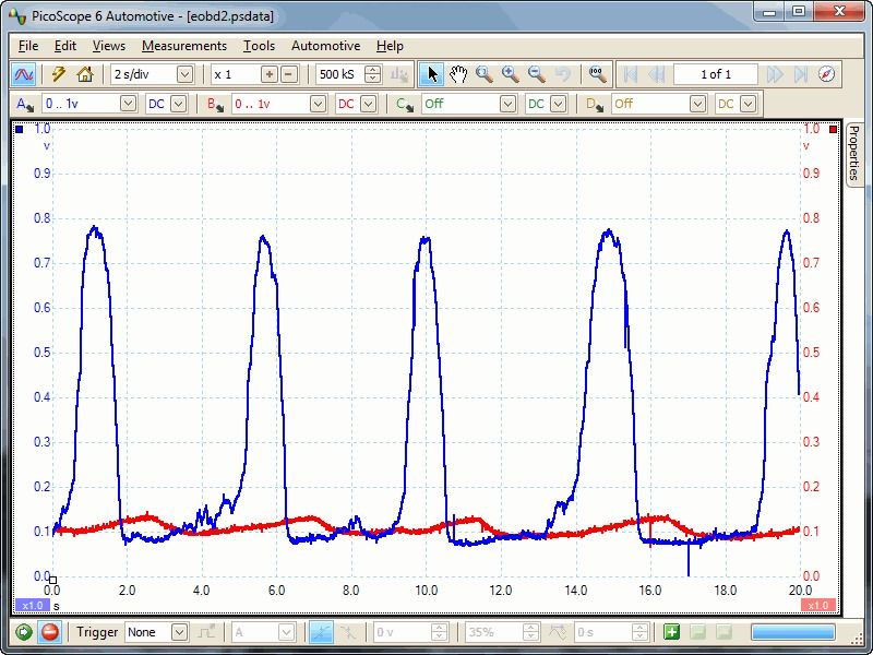
So when we connect the scope up to the signal wire of the sensor and start the engine, after a while the engine goes into closed loop mode and we see this.
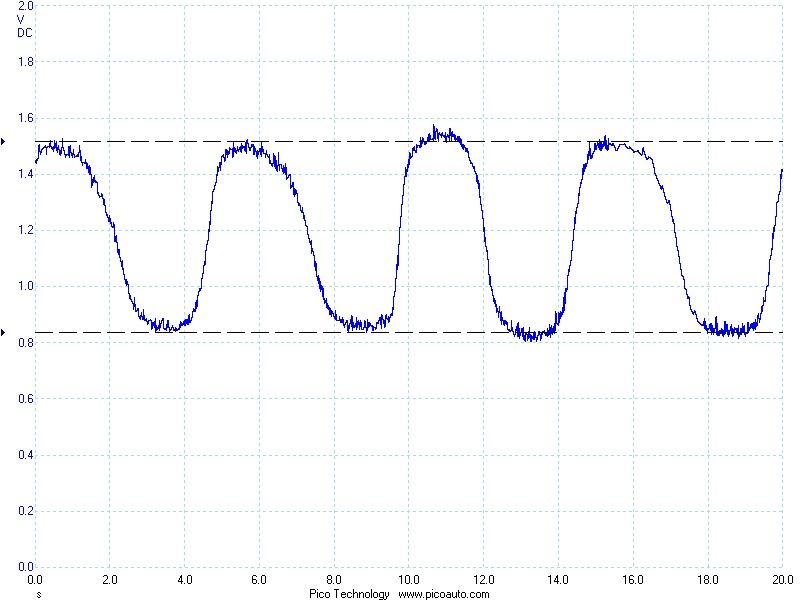
That blue line is the voltage from the lambda sensor, which I'm going to call the O2 sensor from now on because its easier to type. The sensor generates a voltage when oxygen levels in the exhaust gas drop, therefore if the mixture is rich the voltage goes up, if its lean it drops. What we're seeing here is the sensor switching from rich to lean approximatley every 2 seconds. This is how we can tell that the engine is in closed loop mode. The ecu is reacting to the signal and increasing and decreasing the fueling to keep the engine in the lambda window.
The switching speed should generally be around 1hz, or once per second, this sensor is switching on the slow side so I might take it out and give it a clean to see if it improves matters.
Also, a note about the voltage. You remember I said that most sensors switch between 200 and 800 mV, well this one is switching between 800 and 1600. It had me baffled for a while untill I disconnected the sensor and measured .6 volts on the signal wire with the engine running. This is obviously a something volvo have done to give the sensor a larger offset, but if I was trying to track down a running fault and I wasnt aware of that offset it could have caused hours of confusion. This is why its important to know how something works before you try and fix it. I try to get as many good waveforms from diferent cars as I can so I can compare them when I get a fault and I cant see it straight away.
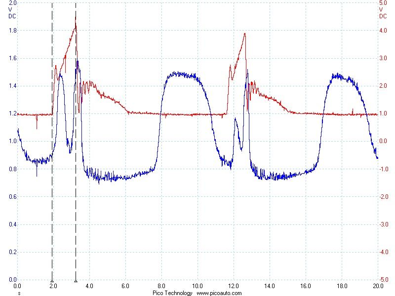
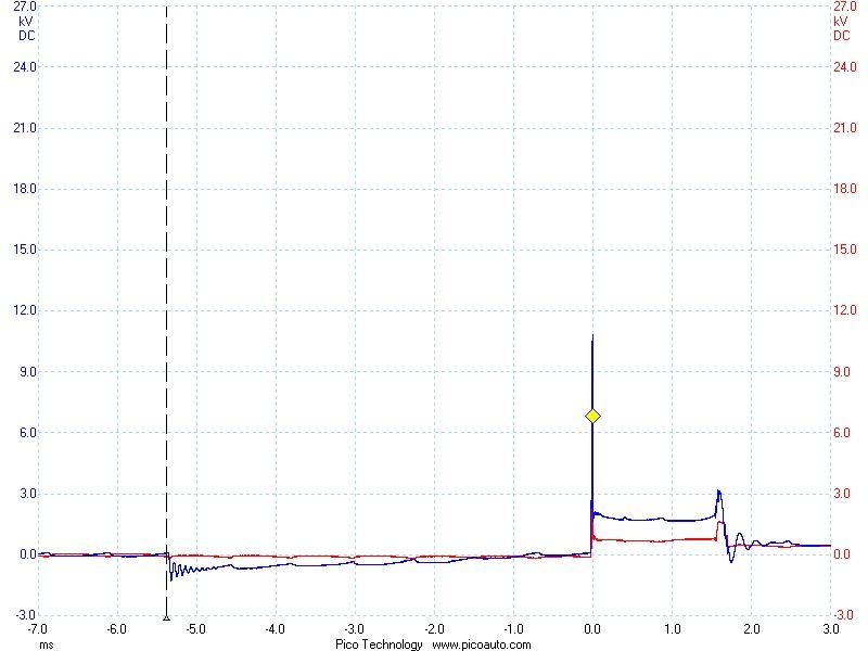
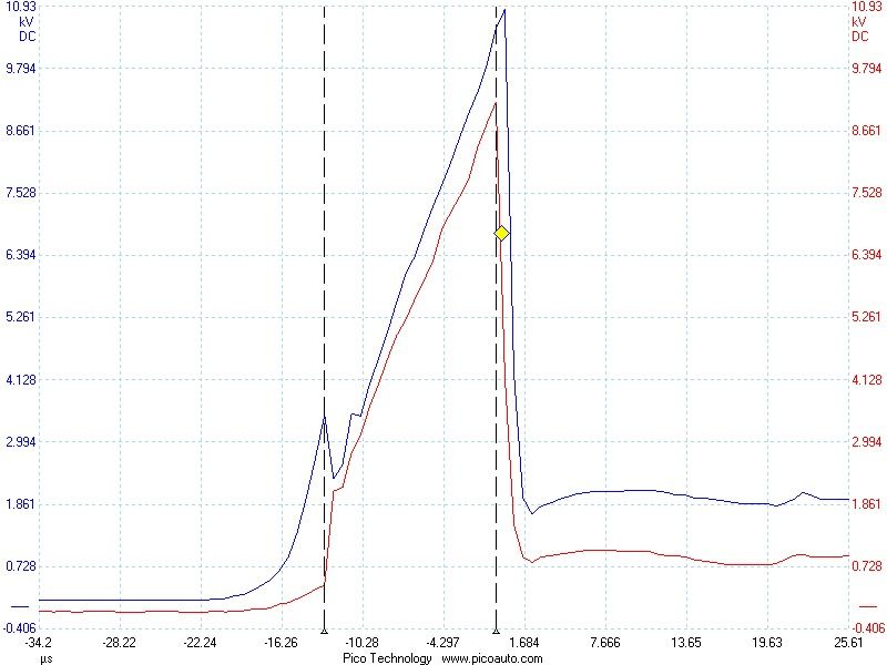
Moving on a bit, lets see what happens to our sensor when I rev the engine. The red trace is the signal from the MAF sensor, or air flow sensor, You can see the voltage increase as the airflow increases.
Now its starting to get exciting ;D
If you look at the first ruler, this is the point where I pressed the pedal. You can see the initial rush of air causes a small peak in the waveform, then it settles down into a steady increase of airflow as the revs go up. Its hard to see the sensor swinging to rich in this particular waveform but what is obvious is that when we lift off the throttle, which is the point where the second ruler is, the ecu cuts the fuel and after a small delay our sensor swings to lean. That small delay is the time it takes for the air to go from the MAF sensor, through the engine and out of the exhaust.
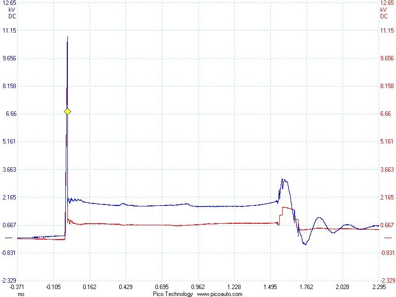
I was still a bit bothered that I hadnt captured a good waveform to show the sensor swinging to rich so I decieded to give the engine a vacuum leak to make it run lean.
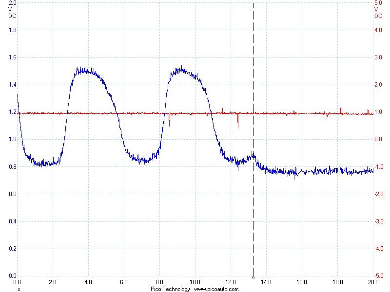
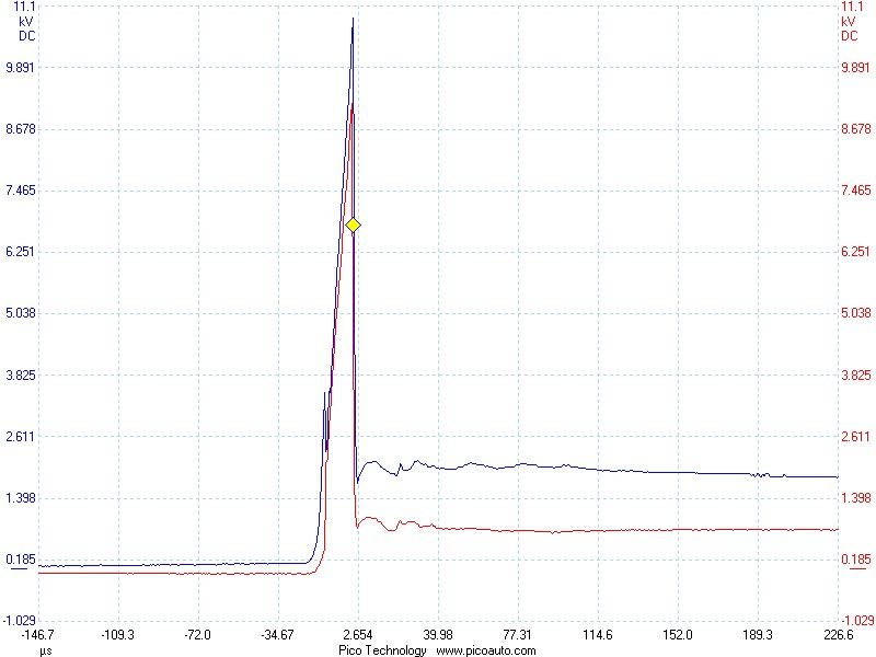
In case you cant see it, I've put a ruler to show the exact point where I pulled the hose off ;D.
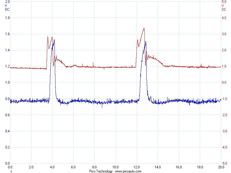
So now we can see exactly where the sensor swings to rich and we can be in no doubt that this is a good sensor that probably just needs a bit of a clean to help it switch a bit quicker.
Hope I didnt bore anyone too much. If theres enough intrest I might do a few more of these showing how different sensors and actuators work and hopefully encourage a few more people to stop being scared of electrics and actually diagnose faults instead of just swapping components untill it runs right again.
They're not exactly expensive either, you can get a simple hand held single channel velman scope from maplins for less than 100 notes. Work out how much you'll save not having to replace MAF sensors, plugs, leads, coils etc to chase a random fault and you can soon see its money well spent.
Anyway, on with the show. There are two types of lambda sensor, zirconia and titania. Zirconia are the most common, also known as narrow band because they operate between 200 and 800 mV (more on that later). The titania type use a much wider voltage scale, around 0 to 5 volts and they require a seperate power supply.
We'll concentrate on zirconia sensors for now because they are more common and they are the type fitted in my car.
So when we connect the scope up to the signal wire of the sensor and start the engine, after a while the engine goes into closed loop mode and we see this.

That blue line is the voltage from the lambda sensor, which I'm going to call the O2 sensor from now on because its easier to type. The sensor generates a voltage when oxygen levels in the exhaust gas drop, therefore if the mixture is rich the voltage goes up, if its lean it drops. What we're seeing here is the sensor switching from rich to lean approximatley every 2 seconds. This is how we can tell that the engine is in closed loop mode. The ecu is reacting to the signal and increasing and decreasing the fueling to keep the engine in the lambda window.
The switching speed should generally be around 1hz, or once per second, this sensor is switching on the slow side so I might take it out and give it a clean to see if it improves matters.
Also, a note about the voltage. You remember I said that most sensors switch between 200 and 800 mV, well this one is switching between 800 and 1600. It had me baffled for a while untill I disconnected the sensor and measured .6 volts on the signal wire with the engine running. This is obviously a something volvo have done to give the sensor a larger offset, but if I was trying to track down a running fault and I wasnt aware of that offset it could have caused hours of confusion. This is why its important to know how something works before you try and fix it. I try to get as many good waveforms from diferent cars as I can so I can compare them when I get a fault and I cant see it straight away.
Moving on a bit, lets see what happens to our sensor when I rev the engine. The red trace is the signal from the MAF sensor, or air flow sensor, You can see the voltage increase as the airflow increases.

Now its starting to get exciting ;D
If you look at the first ruler, this is the point where I pressed the pedal. You can see the initial rush of air causes a small peak in the waveform, then it settles down into a steady increase of airflow as the revs go up. Its hard to see the sensor swinging to rich in this particular waveform but what is obvious is that when we lift off the throttle, which is the point where the second ruler is, the ecu cuts the fuel and after a small delay our sensor swings to lean. That small delay is the time it takes for the air to go from the MAF sensor, through the engine and out of the exhaust.
I was still a bit bothered that I hadnt captured a good waveform to show the sensor swinging to rich so I decieded to give the engine a vacuum leak to make it run lean.

In case you cant see it, I've put a ruler to show the exact point where I pulled the hose off ;D.

So now we can see exactly where the sensor swings to rich and we can be in no doubt that this is a good sensor that probably just needs a bit of a clean to help it switch a bit quicker.
Hope I didnt bore anyone too much. If theres enough intrest I might do a few more of these showing how different sensors and actuators work and hopefully encourage a few more people to stop being scared of electrics and actually diagnose faults instead of just swapping components untill it runs right again.




 Thank you...a very imformative and helpful thread.


