


Not sure where else to put this really, but may be useful to others and should hopefully come up on a google search. I have just finished adding a 3.5mm aux jack to the standard head unit in a Peugeot 309 - this is how I did it and the process may be similar for other head units.
After disassembling the unit, I started looking at the board to see if I could identify the main amplifier chip. If you can find it, it's possible to add your signal from the 3.5mm jack straight to the inputs on the amp chip. I couldn't find anything that looked likely, so instead I focussed on the area where the wires from the tape head meet the main board:
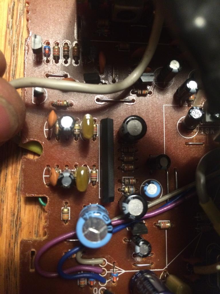
The grey cable comes from the tape head and is soldered to the underside of the board - there are two rows of components, one row for each channel, then an IC. I googled the number on the side of the chip but couldn't find anything, so I ran a search for 'tape head preamplifier' and found this:
Tape Head Preamplifier
The IC in that circuit looks similar, and by looking at the board I was able to see that the pinout is the same - 12v pin 4, ground pin 5, inputs on pins 1 and 8, so I think it's highly likely that the IC on the Clarion board is a Sanyo LA3161 or a copy of it. The purpose of this IC is to amplify the low-level signal from the tape head to line level to feed into the rest of the circuit. The outputs of this chip are on pin 3 and pin 6, so I figured this would be a sensible place to add the signal from the 3.5mm jack. I soldered on a two core shielded wire to the correct pins (L/R may be the wrong way round, I didn't have an easy way of checking and you can always change the wiring on the jack if needed):
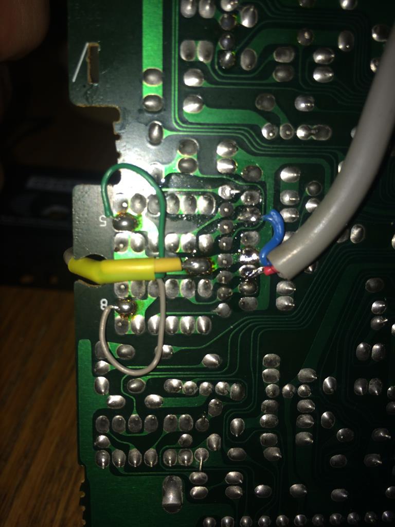
I actually soldered the wires to the next solder pads in the circuit as I was intending to cut the traces on the PCB and use the switching in the 3.5mm jack to change between aux input and the tape deck but in the end it wasn't needed as the tape head doesn't seem to cause any noise problems left connected. The shield of the cable needs to be connected to ground (pin 5) and the other two wires need to go to the outputs of the chip (3 & 6). You could probably get away without shielded cable, but I had some lying around. Hot glue was added afterwards to secure the cable.
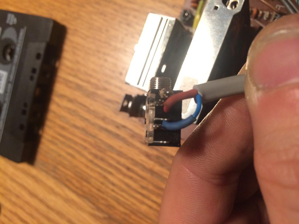
I then needed to decide where to mount the 3.5mm jack and run the shielded cable to that point. I was going to mount it on the back of the head unit to keep it hidden, but I found the cable got in the way of the tape mechanism, so in the end mounted it on the front panel. I had to cut away part of a metal bracket and half the PCB for the anti-theft LED to get it to fit, but it works pretty well. Cable soldered to the jack:
And fitted:
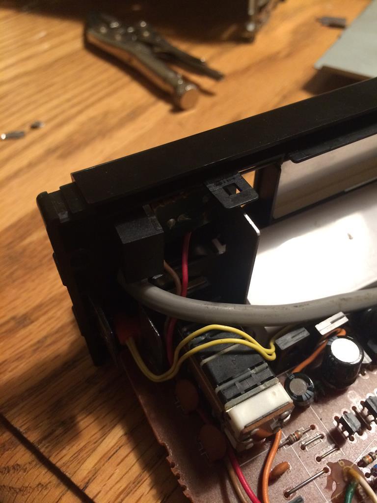
Edit: in order to drill the hole and fit the jack, I had to remove the faceplate of the stereo. This is achieved by pulling the volume knob off the spindle then carefully prying the tone control off, exposing a nut. I used a pair of needle-nosed pliers to remove the nut as it was not massively tight. Once the nut is removed, the faceplate should come away from the board after releasing the clips at the other end.
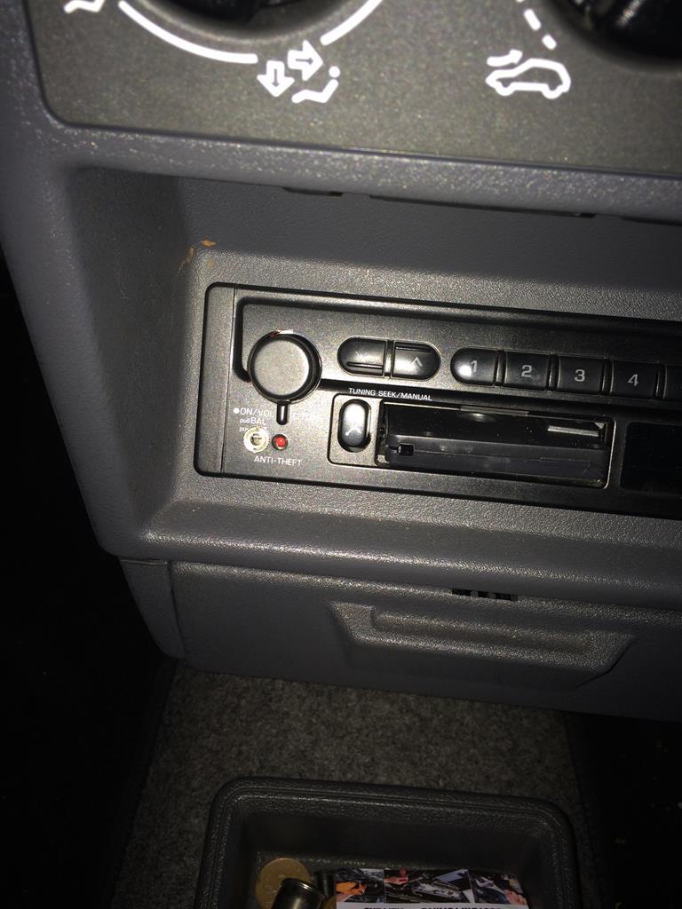
In order for the head unit to accept the auxiliary input, it needs to have a tape inserted. I gutted an old MP3 tape adapter to leave just the shell with no mechanism, so that it doesn't make any noise but still causes the head unit to switch. You could also use a normal cassette with all the guts removed. At this point I tested the mod and found that it sounded great, much better than the tape adapter. The unit was reassembled and refitted. This is the final result:
You could mount the jack elsewhere if you want - you could run the shielded cable out of the head unit and fit the jack in a glovebox, ash tray etc. This mod was very much worth doing as it costs hardly anything but offers a big improvement in sound quality over a tape adapter while keeping the original head unit. If anyone has any suggestions on how this could've been done better or if they've done something similar I'd be very interested to hear from you.
After disassembling the unit, I started looking at the board to see if I could identify the main amplifier chip. If you can find it, it's possible to add your signal from the 3.5mm jack straight to the inputs on the amp chip. I couldn't find anything that looked likely, so instead I focussed on the area where the wires from the tape head meet the main board:
The grey cable comes from the tape head and is soldered to the underside of the board - there are two rows of components, one row for each channel, then an IC. I googled the number on the side of the chip but couldn't find anything, so I ran a search for 'tape head preamplifier' and found this:
Tape Head Preamplifier
The IC in that circuit looks similar, and by looking at the board I was able to see that the pinout is the same - 12v pin 4, ground pin 5, inputs on pins 1 and 8, so I think it's highly likely that the IC on the Clarion board is a Sanyo LA3161 or a copy of it. The purpose of this IC is to amplify the low-level signal from the tape head to line level to feed into the rest of the circuit. The outputs of this chip are on pin 3 and pin 6, so I figured this would be a sensible place to add the signal from the 3.5mm jack. I soldered on a two core shielded wire to the correct pins (L/R may be the wrong way round, I didn't have an easy way of checking and you can always change the wiring on the jack if needed):
I actually soldered the wires to the next solder pads in the circuit as I was intending to cut the traces on the PCB and use the switching in the 3.5mm jack to change between aux input and the tape deck but in the end it wasn't needed as the tape head doesn't seem to cause any noise problems left connected. The shield of the cable needs to be connected to ground (pin 5) and the other two wires need to go to the outputs of the chip (3 & 6). You could probably get away without shielded cable, but I had some lying around. Hot glue was added afterwards to secure the cable.
I then needed to decide where to mount the 3.5mm jack and run the shielded cable to that point. I was going to mount it on the back of the head unit to keep it hidden, but I found the cable got in the way of the tape mechanism, so in the end mounted it on the front panel. I had to cut away part of a metal bracket and half the PCB for the anti-theft LED to get it to fit, but it works pretty well. Cable soldered to the jack:
And fitted:
Edit: in order to drill the hole and fit the jack, I had to remove the faceplate of the stereo. This is achieved by pulling the volume knob off the spindle then carefully prying the tone control off, exposing a nut. I used a pair of needle-nosed pliers to remove the nut as it was not massively tight. Once the nut is removed, the faceplate should come away from the board after releasing the clips at the other end.
In order for the head unit to accept the auxiliary input, it needs to have a tape inserted. I gutted an old MP3 tape adapter to leave just the shell with no mechanism, so that it doesn't make any noise but still causes the head unit to switch. You could also use a normal cassette with all the guts removed. At this point I tested the mod and found that it sounded great, much better than the tape adapter. The unit was reassembled and refitted. This is the final result:
You could mount the jack elsewhere if you want - you could run the shielded cable out of the head unit and fit the jack in a glovebox, ash tray etc. This mod was very much worth doing as it costs hardly anything but offers a big improvement in sound quality over a tape adapter while keeping the original head unit. If anyone has any suggestions on how this could've been done better or if they've done something similar I'd be very interested to hear from you.


