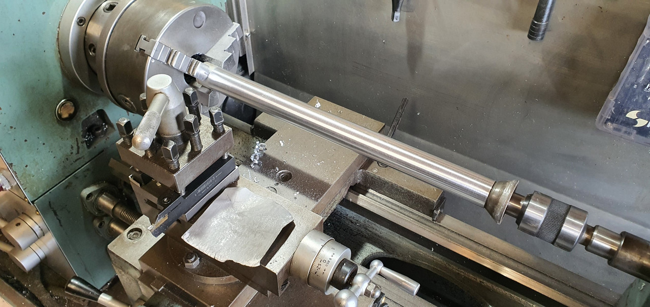
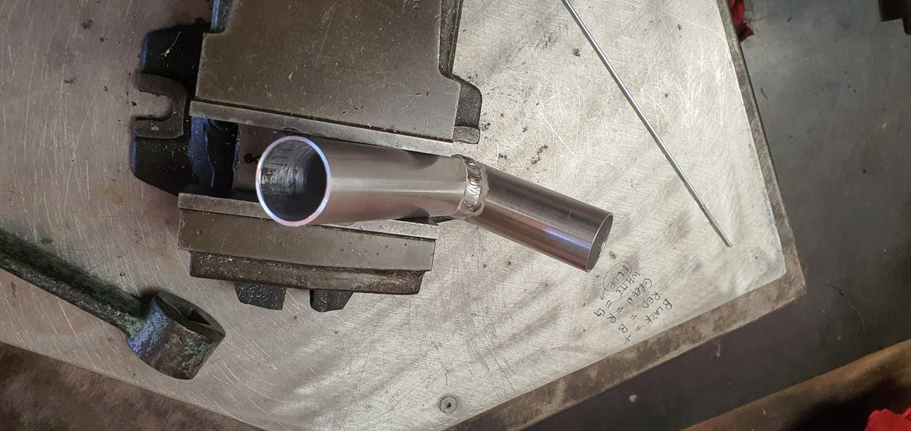
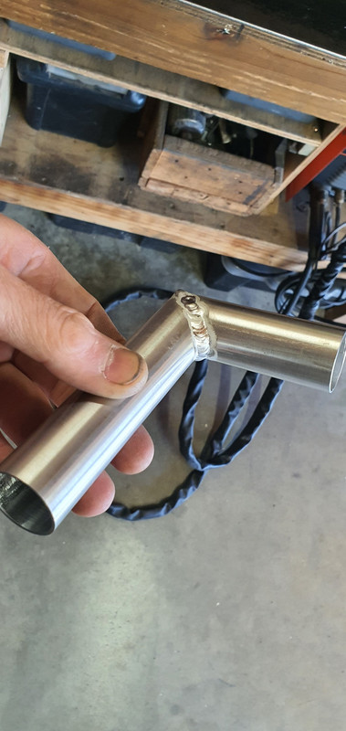
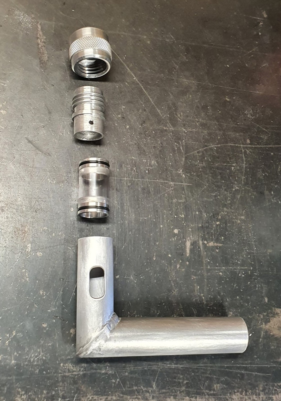
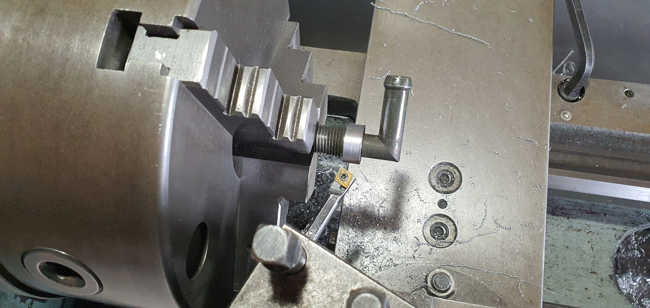
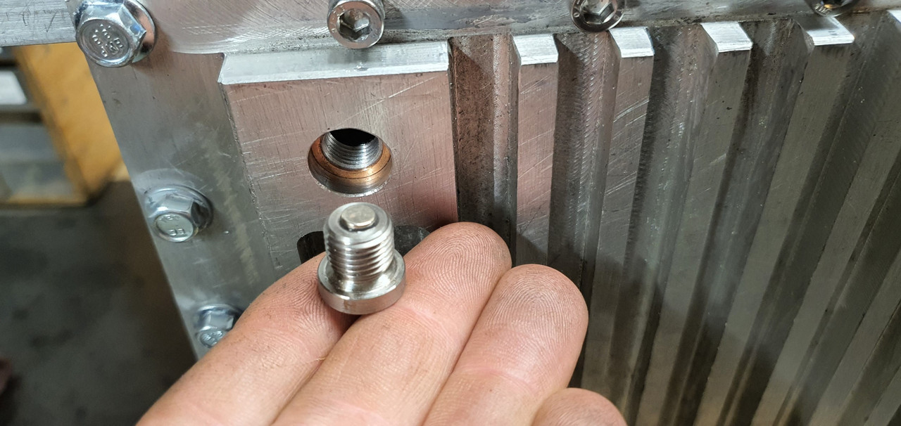
So where I left off last time was the oil filler pipe and sight window ideas. I don't really need a separate flange now I have decided to run the pipe shorter in height. So I dug out another old bit of alloy, gave a it a clean in the lathe and welded up a new pipe..
While in Nelson city a week or so ago I popped into a plastic place that told me on the phone they had 25mm thick walled acrylic tube. Turned out they didn't and instead I left with some thin walled lexan (polycarbonate) tube, closer to 25.4 in size. It was cheap so I thought it gives me something to play with. I picked up some thin 25mm O-rings on the way home and started to suss out a way I could make it work.
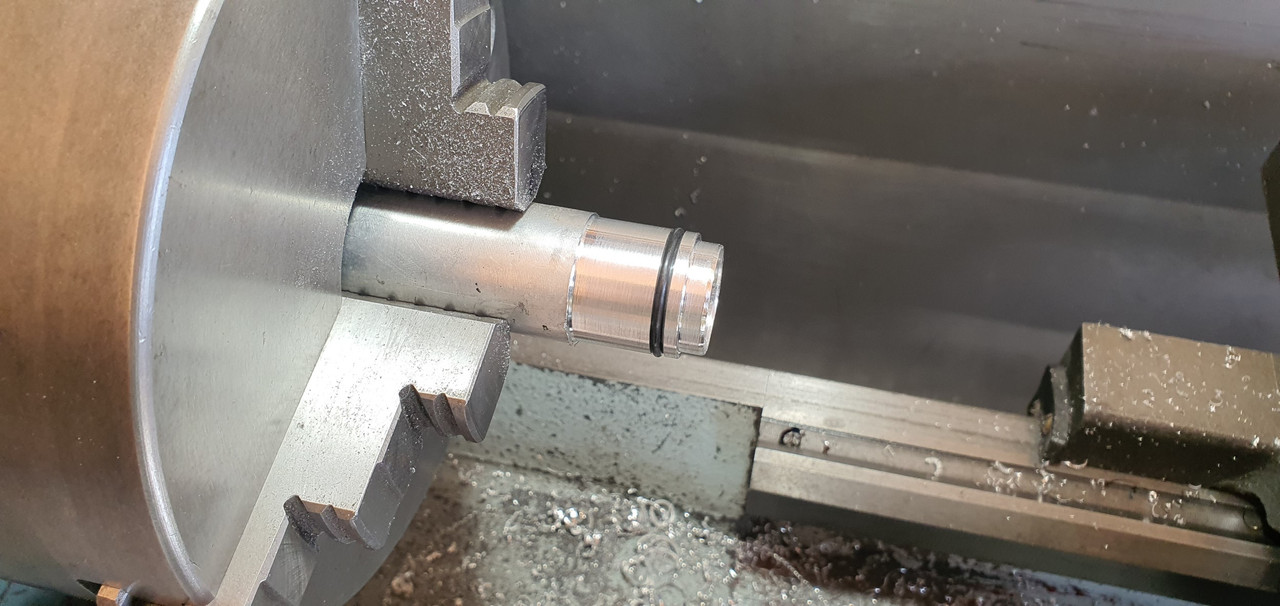
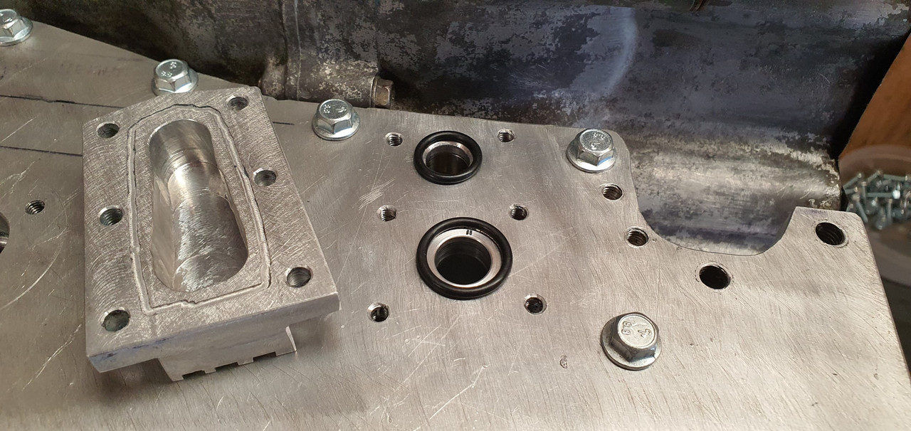
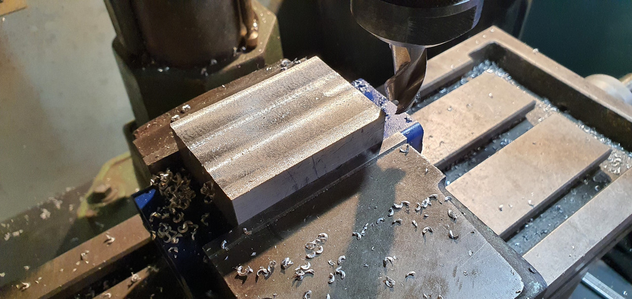
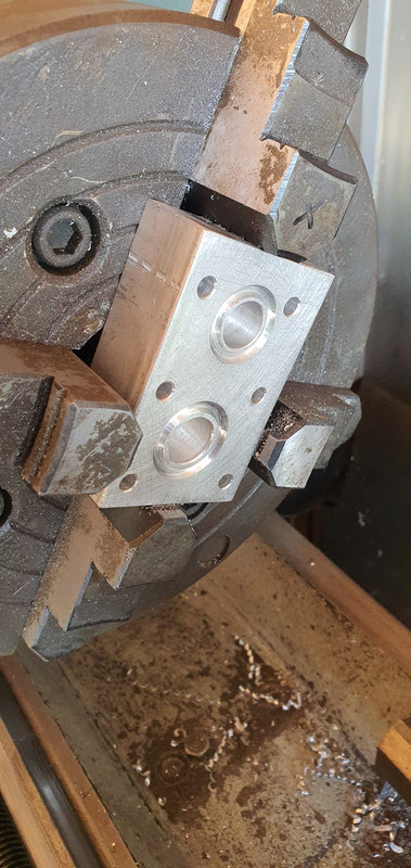
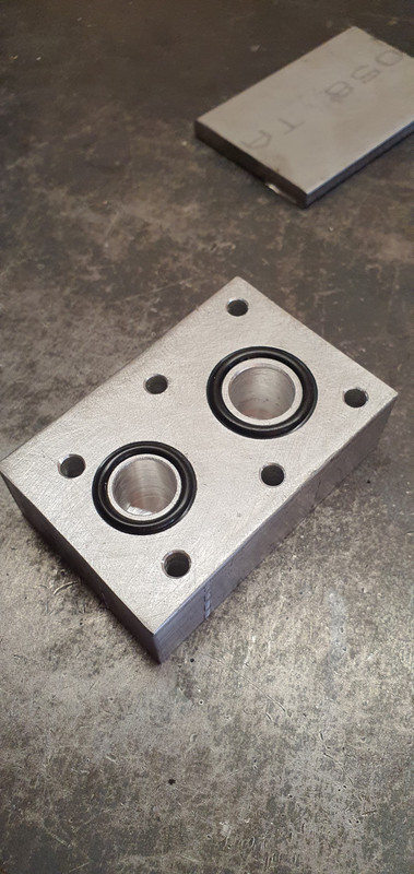
The plastic was way too thin to machine Oring grooves into so instead I machined some alloy ends with grooves.
Cut a short length of plastic tube to suit..
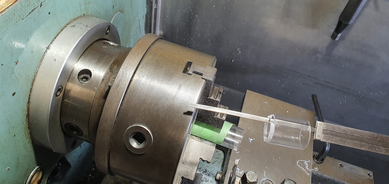
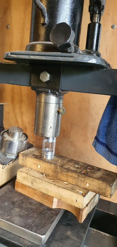
Which was pressed onto the end caps..
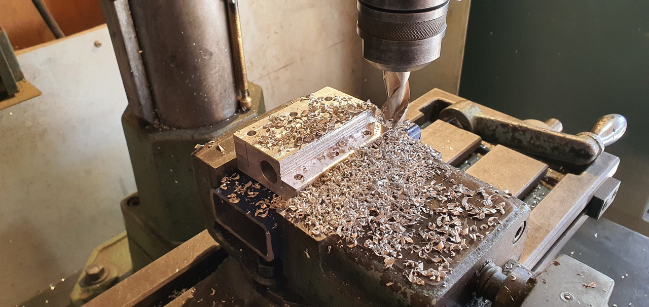
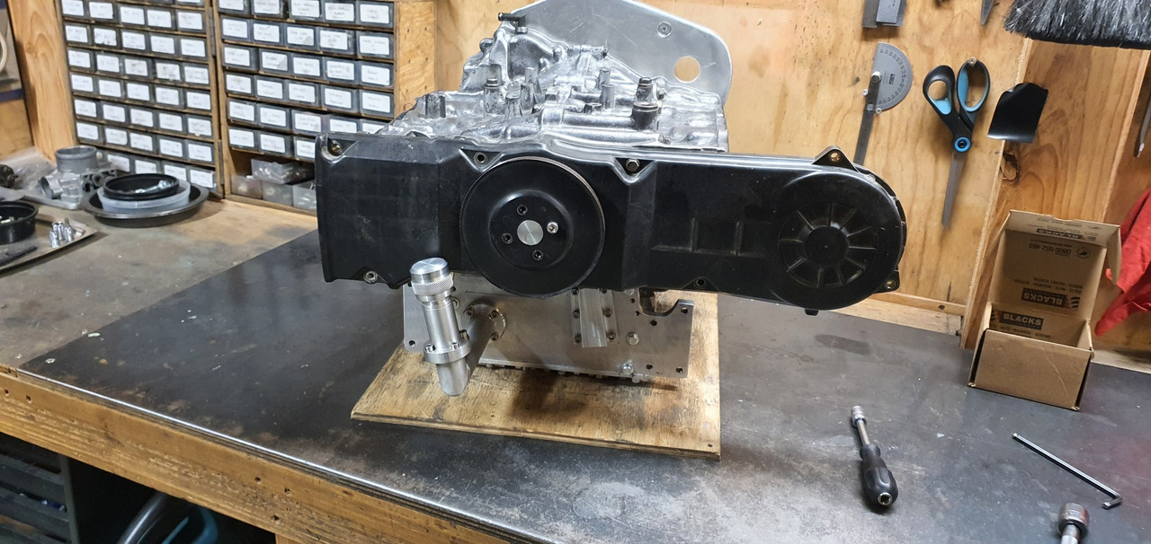
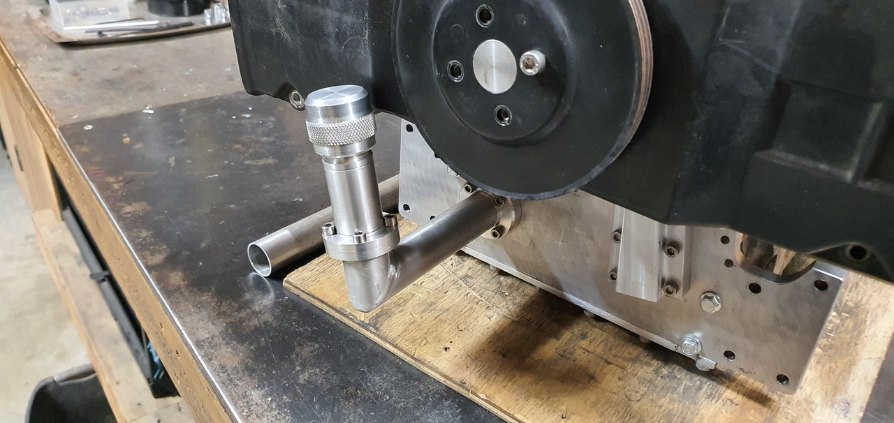
I milled a window into the side of the filler pipe. Now I had some bits to assemble..
Fitted in place..
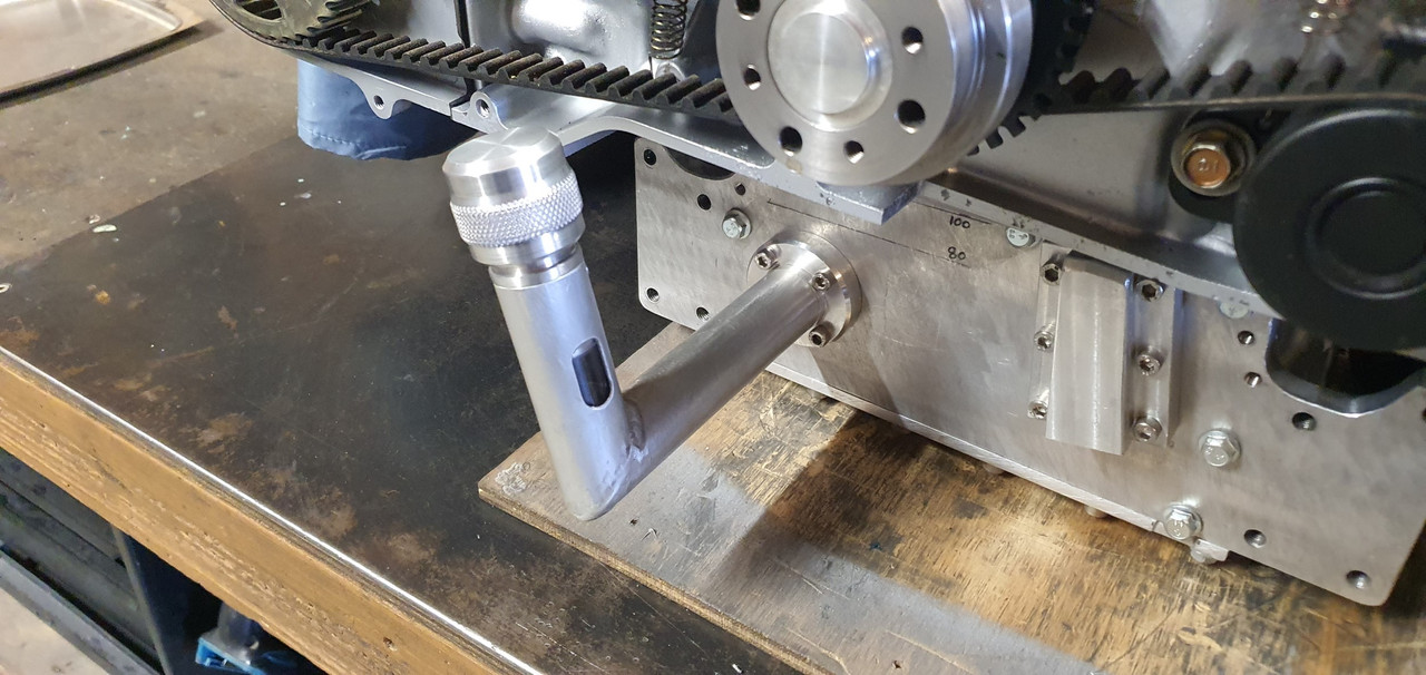
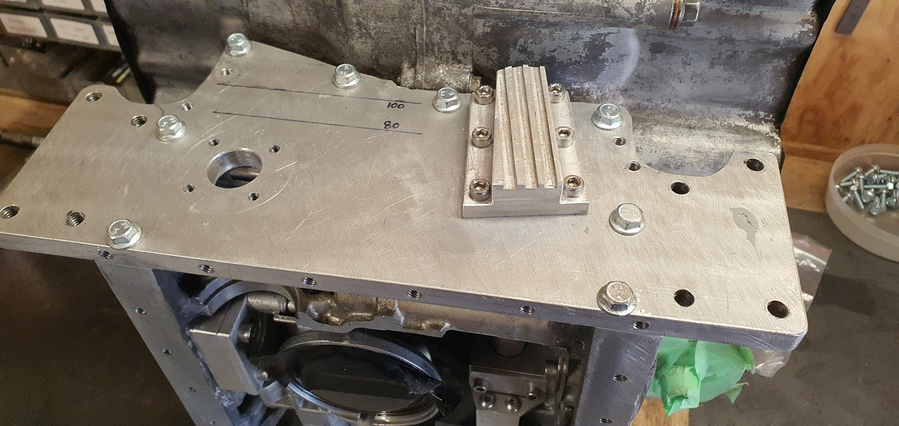
The bottom of the stub which the filler cap screws onto is pretty much at 100mm oil height. Bottom of the sight is 80mm. So if I aim for a 90mm height I'm smack in the middle.
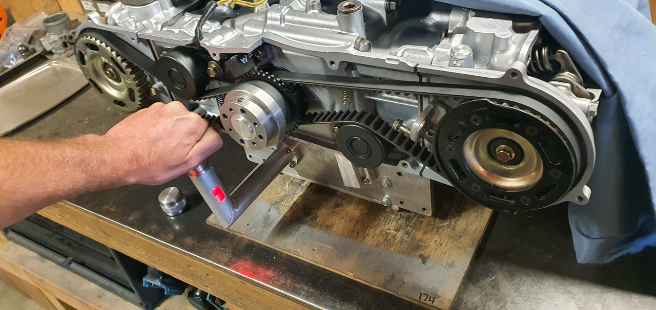
Some led keychain trinkets turned up in the mail from China and I have a metal 'momentarily on' switch from Jaycar electronics. I'll have a play about and see if I can make a neat enough attempt fitting it within the filler cap so it does something like this (using a bike light)...
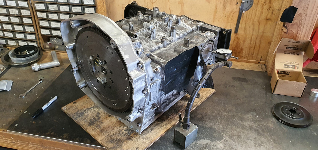
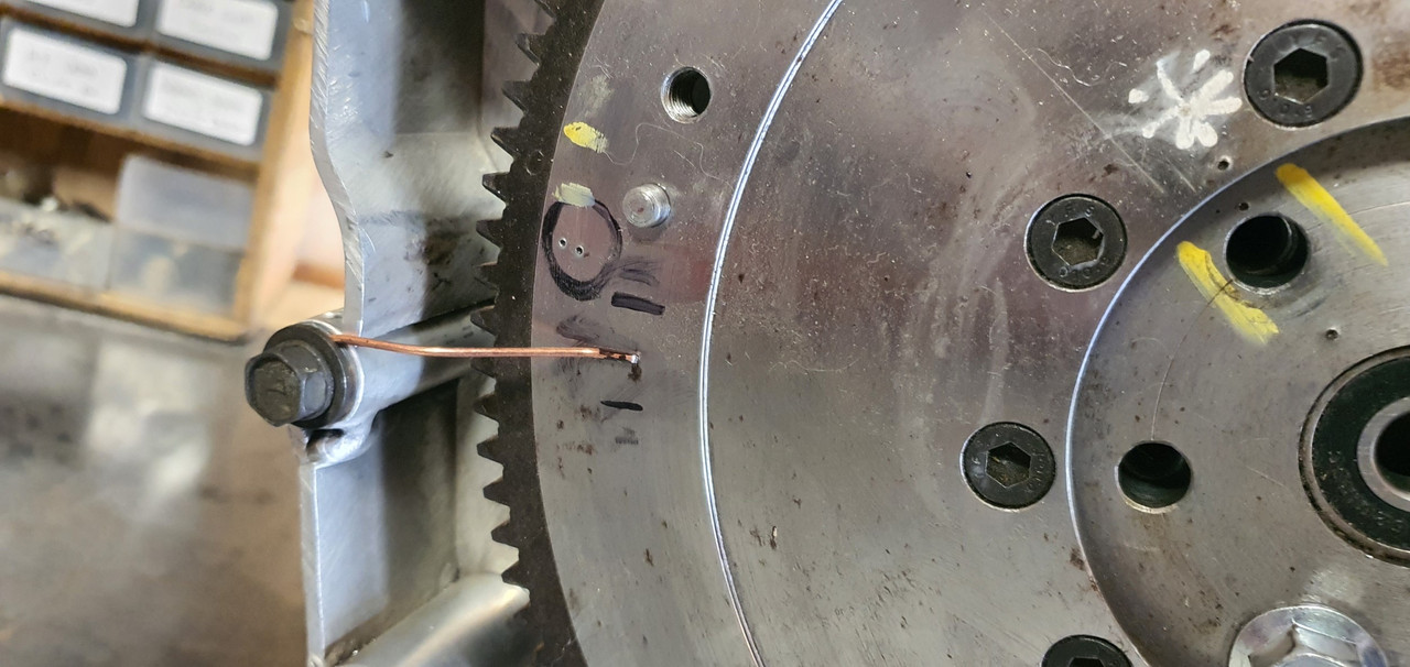
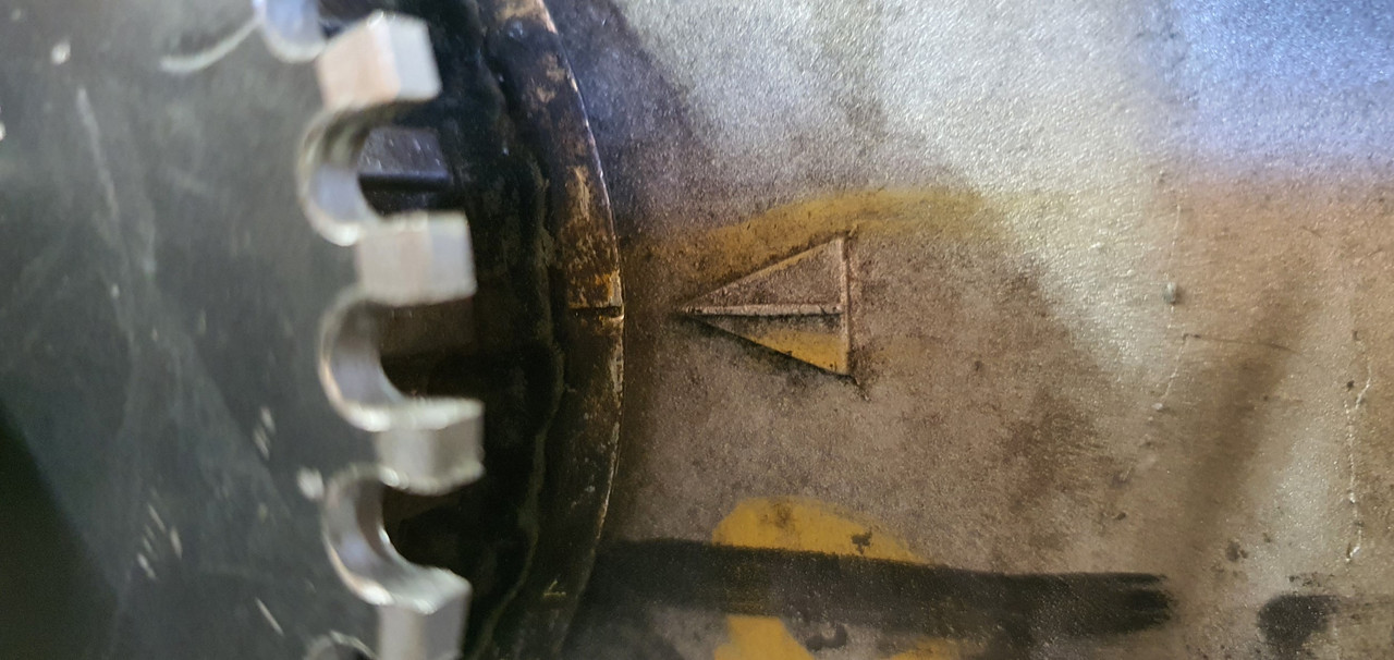
Back to proper jobs now. Painting and finish assembly. First though I wanted to check the TDC marks are correct and make some timing marks to suit on my alternator pulley. I set a DTI up and found TDC. Luckily it seems the factory marks are bang on.
Paint time.
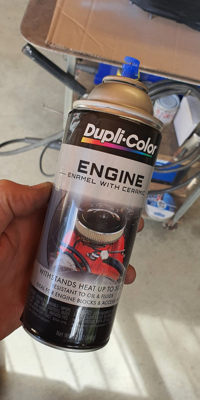
I had bought some paint for the engine a while ago. I gave the block and heads one last clean and masked them up.
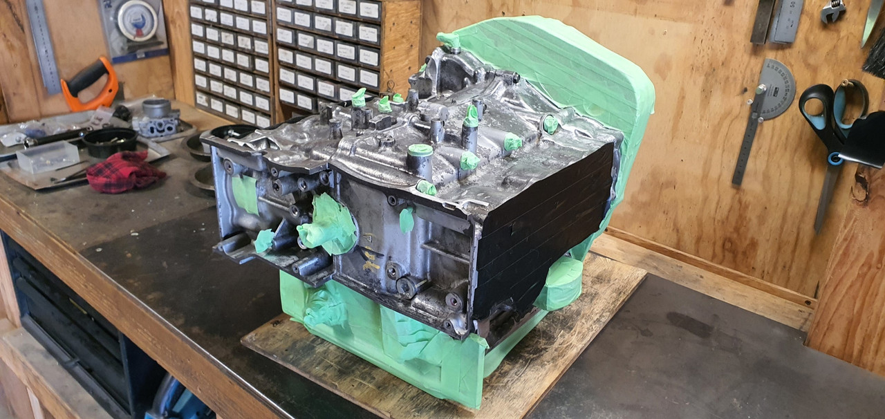
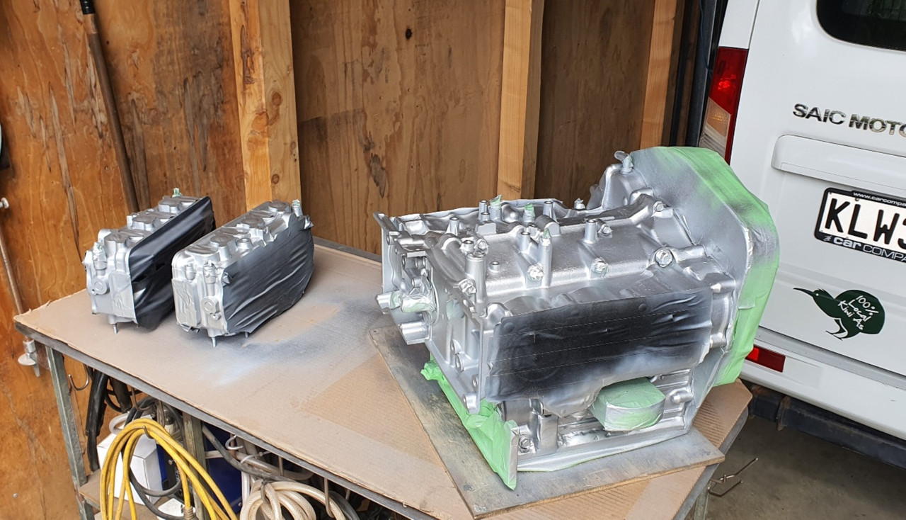
Primer first..
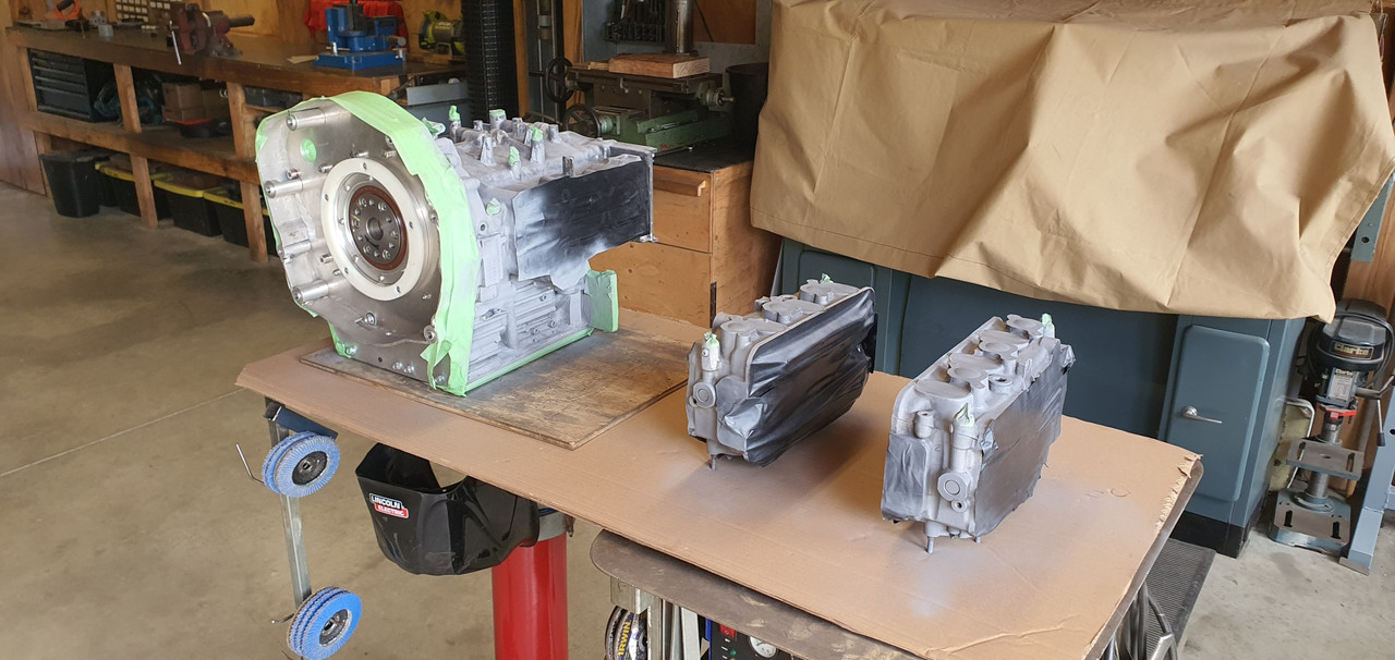
Then top coat. I decided on alloy finish, similar to the original colour. Really just too tidy it up and stop the alloy getting that annoying light corrosion.
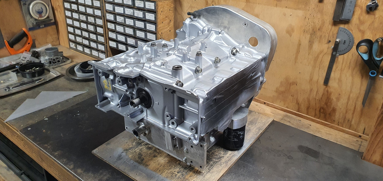
Then that fun job of removing masking tape to reveal a neat finish..
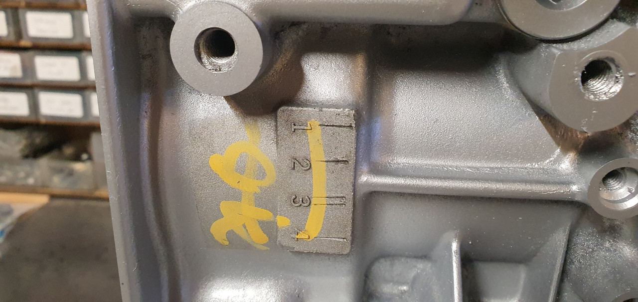
I masked over the original hand painted OK checks - just because I like them.
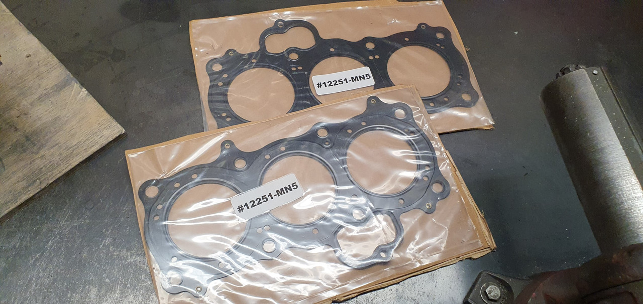
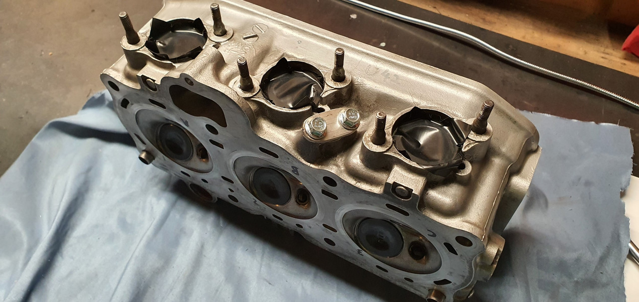
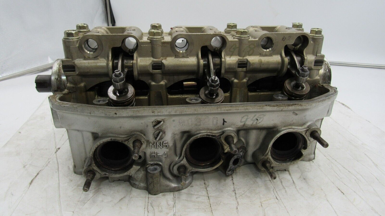
Engine painted I dug out the brand new head gaskets Id bought very early on...
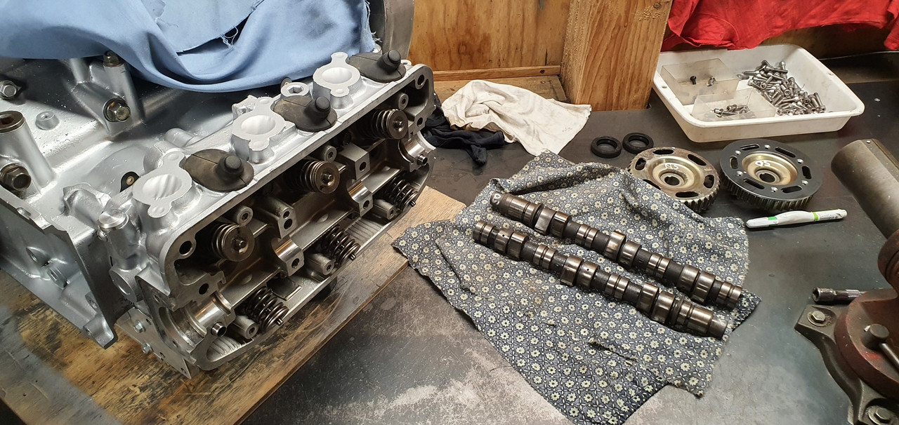
Torqued the heads in place and then moved onto the camshafts/camshaft and follower housings..
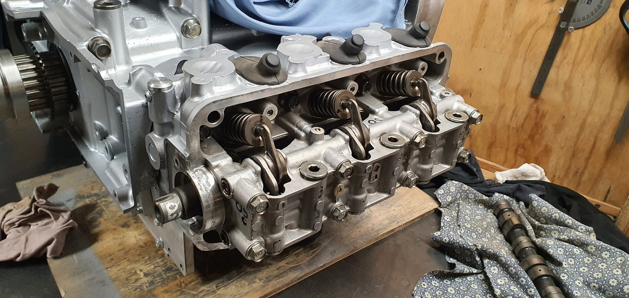
In place...
Now I needed to finish the trigger wheels which meant getting them phased in the correct position
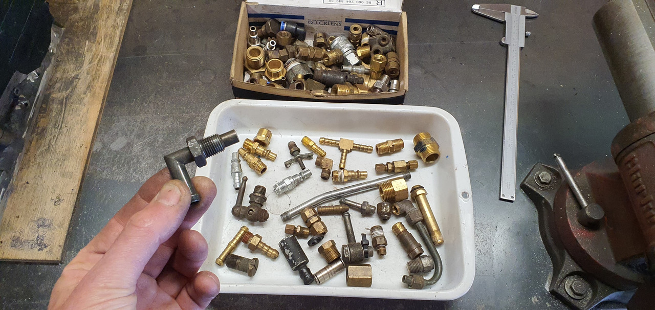
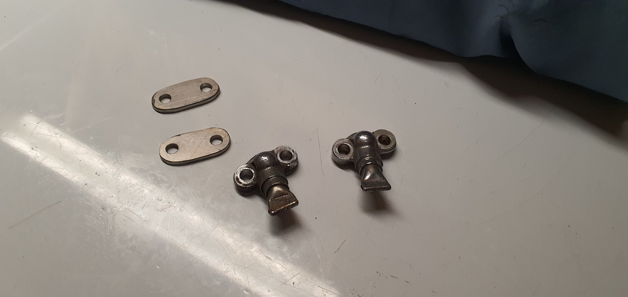
I laid out all the bits that go with the cam covers and pulleys.
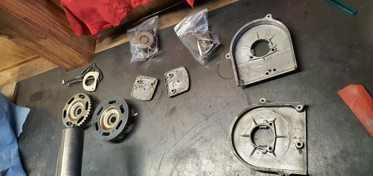
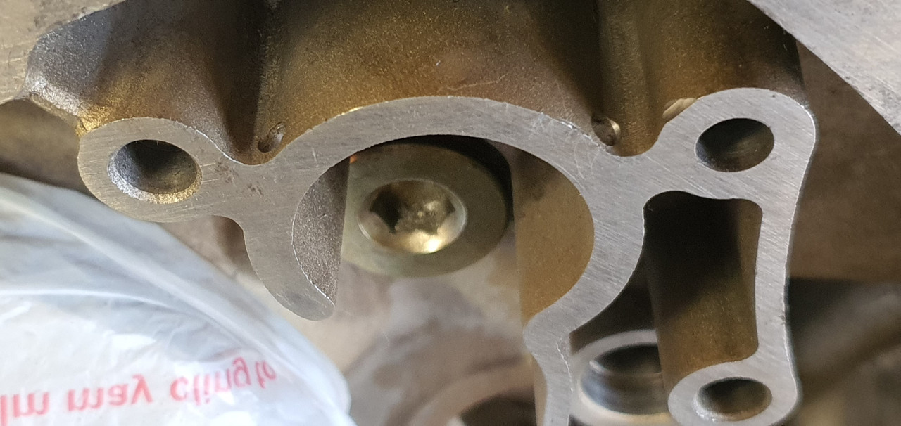
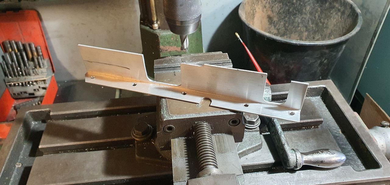
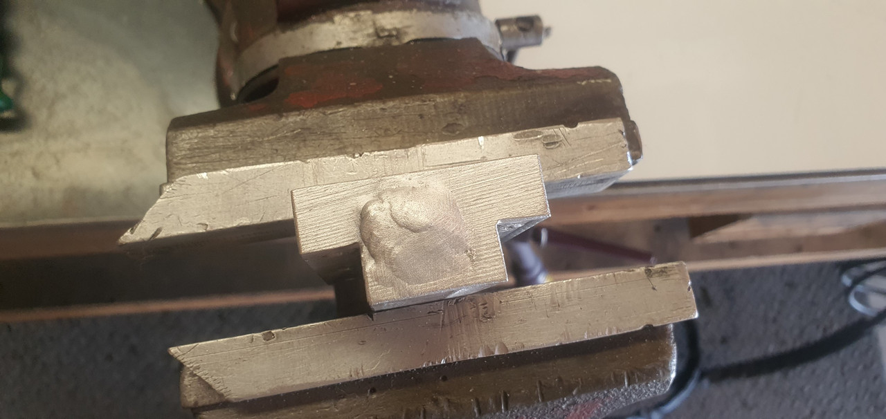
This alloy bit was damaged from when the original Goldwing bike must have been dropped (I think the engine must have come from a low mileage bike that had been involved in an accident many moons ago)
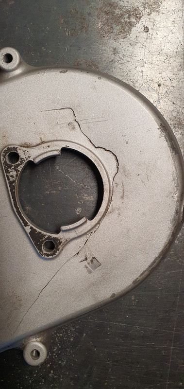
It wasn't sitting flat and needed a bit of a straighten..
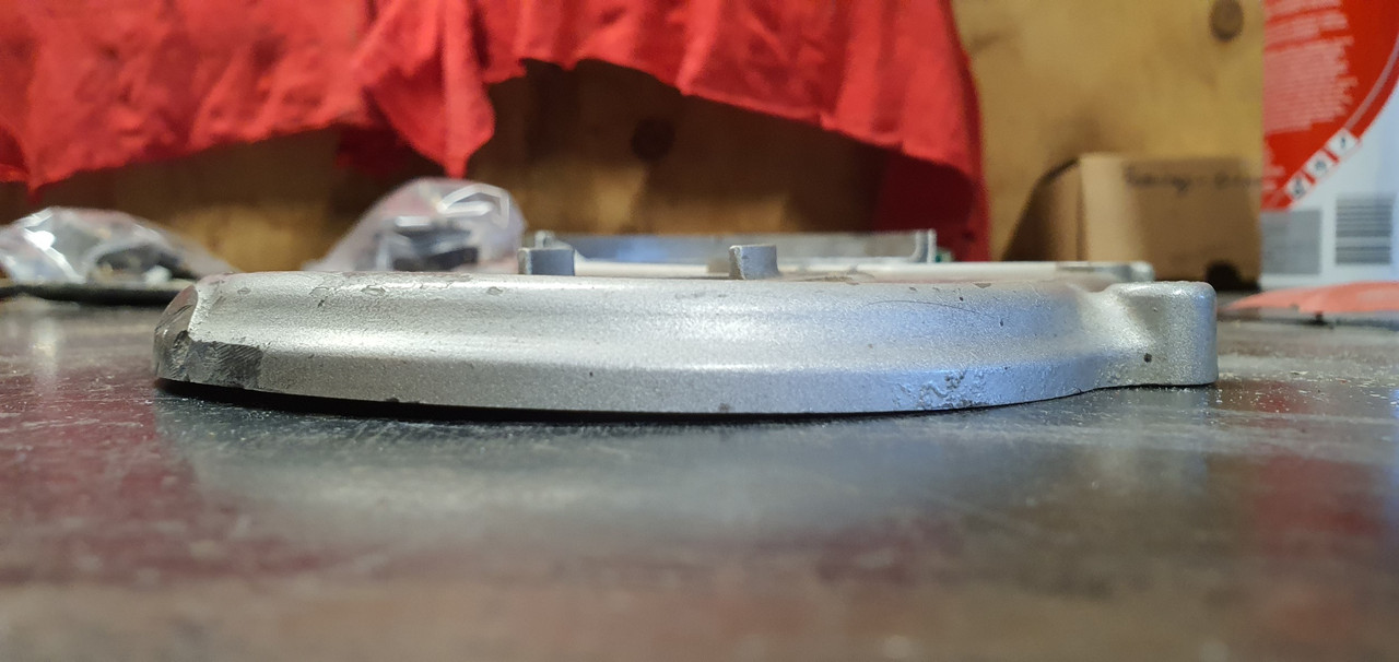
Simple I thought. I'll use the press. I carefully set it up on the press with various bit of metal so I could bend it back straight. I got it pretty good - but it needed just a little bit more...
Bang!
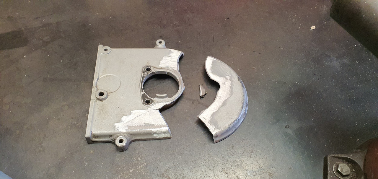
Whoops.
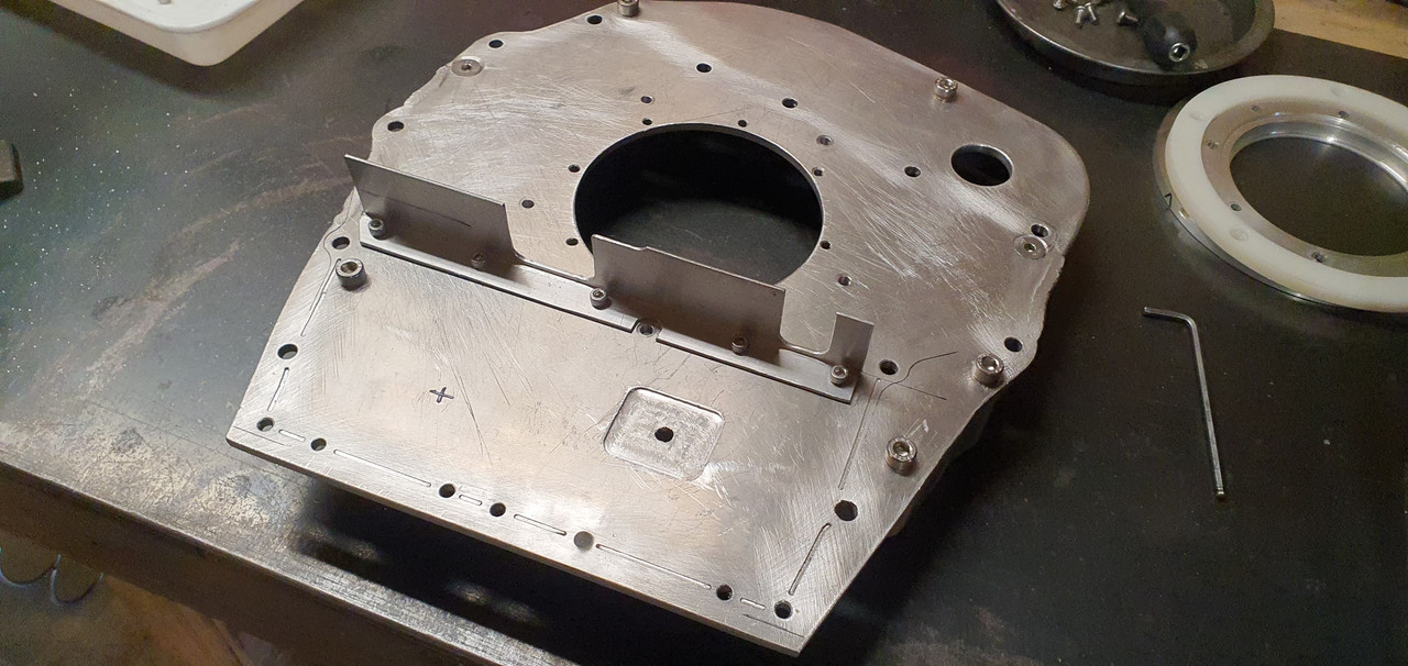
* Pic is taken after I'd already started prepping it to weld.
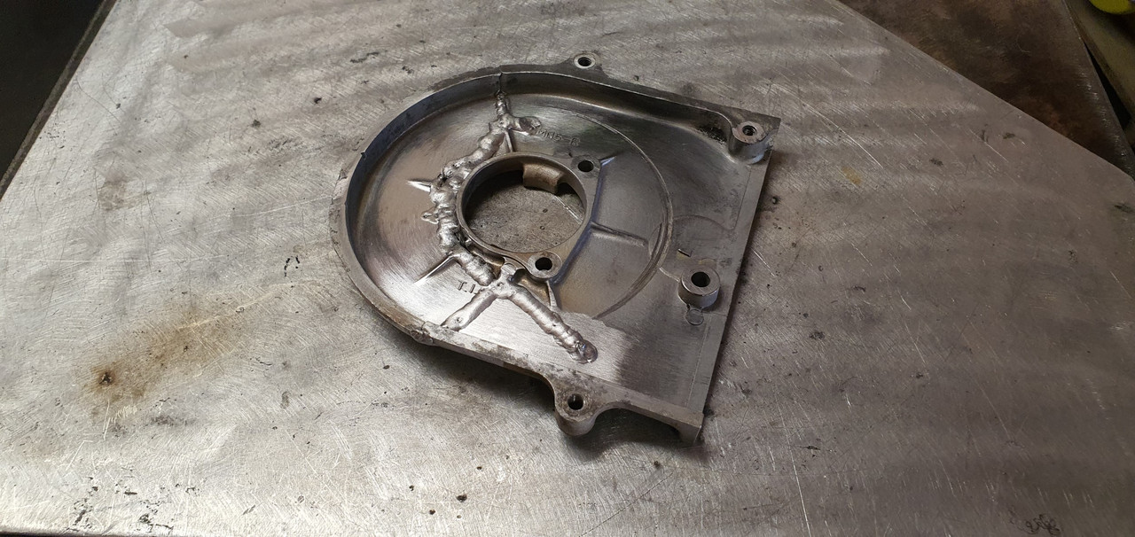
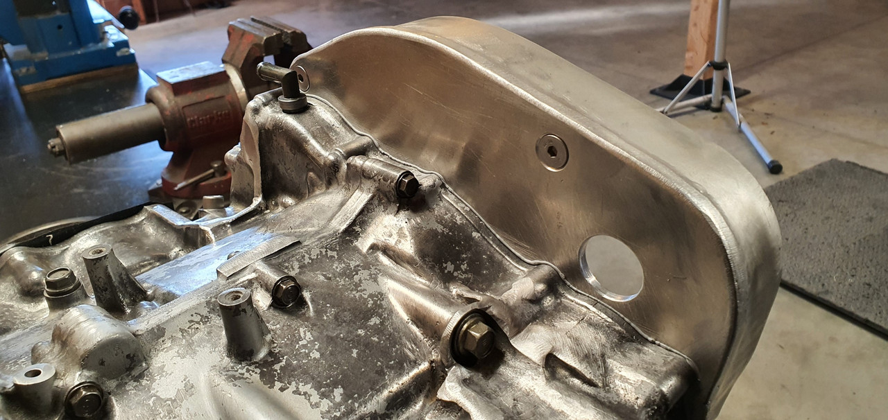
I preheated it in the oven and then carefully sticthed it back together. Not the nicest casting to weld but it turned out ok and luckily the repairs are not on display..
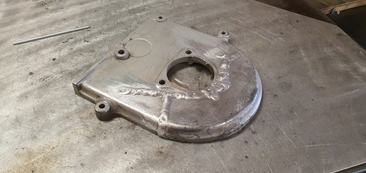
Welded both sides..
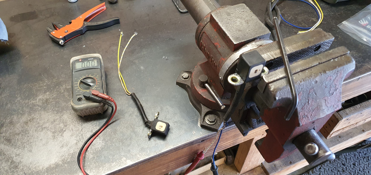
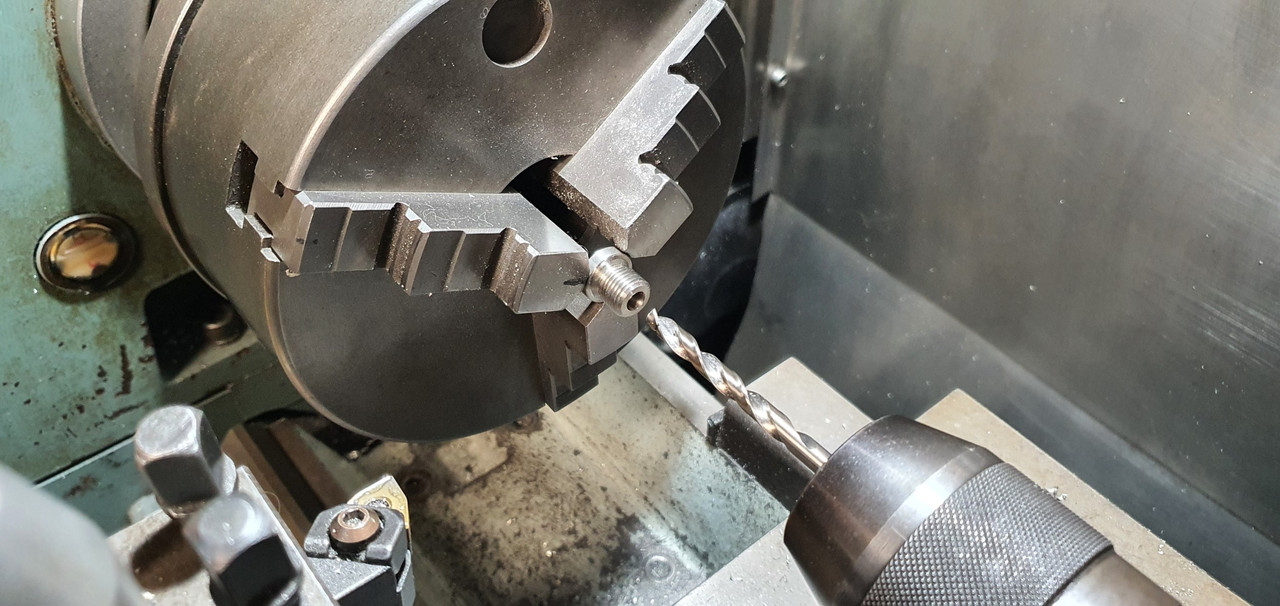
Trigger wheel time. First off I wanted to work out the wire polarity on the oem goldwing VR sensors..
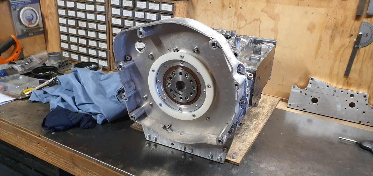
Now I knew the timing marks are good I set up the main crank position trigger wheel in place and marked it. Then welded a stub of steel in place which was cut down to form a key that locates in the cranks keyway.
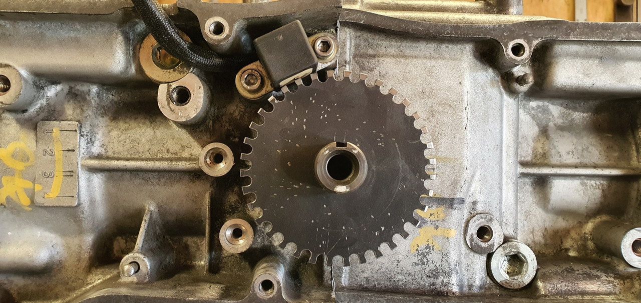
I doubled checked the megasquirt MS extra build manual and removed the appropriate tooth so creating a 36 - 1 trigger wheel with a 50 degree offset.
Then I fitted the brand new Gates cambelts I had also bought ages ago. Sadly I discovered they are English made which means they'll probably leak..
.jpg)
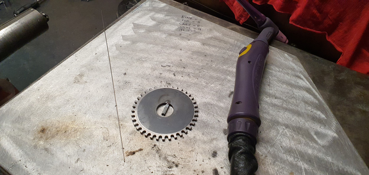
Now I could setup the camshaft position sensor trigger wheel - needed so I can run the injection mode as fully sequential.
I had made this wheel a while back but had not yet removed the half moon of material. Annoyingly I forgot to weigh the wheel before I removed material. I now had no real accurate way of working out what to mill off the opposite side to balance the wheel out. Balancing it is probably not super critical but considering that at 6000rpm this wheel will be doing 3000 rpm I really wanted to avoid any extra throw out stress on the pulley or camshaft/camshaft bearings.
The final nail in the coffin for this wheel was it slipping in my makeshift rotary table (actually just the mill vice which can be rotated to mill the concentric slot - which I did by hand)
.jpg)
It slipped, the end mill grabbed and became two pieces with a loud bang.
.jpg)
So I made a new wheel. This time I weighed it before removing the halfmoon. Then I was able to mill the exact right amount off to balance it as best I could.
.jpg)
Weighing it before milling out the final weight reduction slots..
.jpg)
Setup in place..
.jpg)
.jpg)
All that sorted I could move on to a fun little job I was looking forward to. Painting the cam covers and sorting out replacements for the old badges.
.jpg)
.jpg)
After a really good clean and some light sanding of the covers, which have been through the wars and have extensive welding repairs due to the same crash I guess, I laid down some primer.
.jpg)
See one repair here...
.jpg)
Due to the fairly rough finish I decided on wrinkle finish paint because it can hide sins and blemishes. I've used this same product to good success on that Mazda V6 I had plonked into my Viva HB so I was pretty confident on getting an OK finish. Covers were warmed up in the sunshine and 3 thick coats were laid down, 5 minutes between each coat.
.jpg)
Once the paint did its magic thing they came up ok. I'm happy.
.jpg)
Now the badges. I was going to try a couple of mates about getting something with the word HONDA 3d printed or machined in alloy but I really wanted to do it all myself and thought about some nice machined ribs to insert.
.jpg)
they turned out neat..
.jpg)
Carefully fixed in place as per original badges with double sided foam tape...
.jpg)
Covers bolted up in place. I'm really happy with the look
.jpg)
.jpg)
While in Nelson city a week or so ago I popped into a plastic place that told me on the phone they had 25mm thick walled acrylic tube. Turned out they didn't and instead I left with some thin walled lexan (polycarbonate) tube, closer to 25.4 in size. It was cheap so I thought it gives me something to play with. I picked up some thin 25mm O-rings on the way home and started to suss out a way I could make it work.
The plastic was way too thin to machine Oring grooves into so instead I machined some alloy ends with grooves.
Cut a short length of plastic tube to suit..
Which was pressed onto the end caps..
I milled a window into the side of the filler pipe. Now I had some bits to assemble..
Fitted in place..
The bottom of the stub which the filler cap screws onto is pretty much at 100mm oil height. Bottom of the sight is 80mm. So if I aim for a 90mm height I'm smack in the middle.
Some led keychain trinkets turned up in the mail from China and I have a metal 'momentarily on' switch from Jaycar electronics. I'll have a play about and see if I can make a neat enough attempt fitting it within the filler cap so it does something like this (using a bike light)...
Back to proper jobs now. Painting and finish assembly. First though I wanted to check the TDC marks are correct and make some timing marks to suit on my alternator pulley. I set a DTI up and found TDC. Luckily it seems the factory marks are bang on.
Paint time.
I had bought some paint for the engine a while ago. I gave the block and heads one last clean and masked them up.
Primer first..
Then top coat. I decided on alloy finish, similar to the original colour. Really just too tidy it up and stop the alloy getting that annoying light corrosion.
Then that fun job of removing masking tape to reveal a neat finish..
I masked over the original hand painted OK checks - just because I like them.
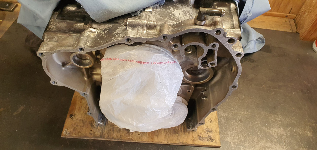
Engine painted I dug out the brand new head gaskets Id bought very early on...
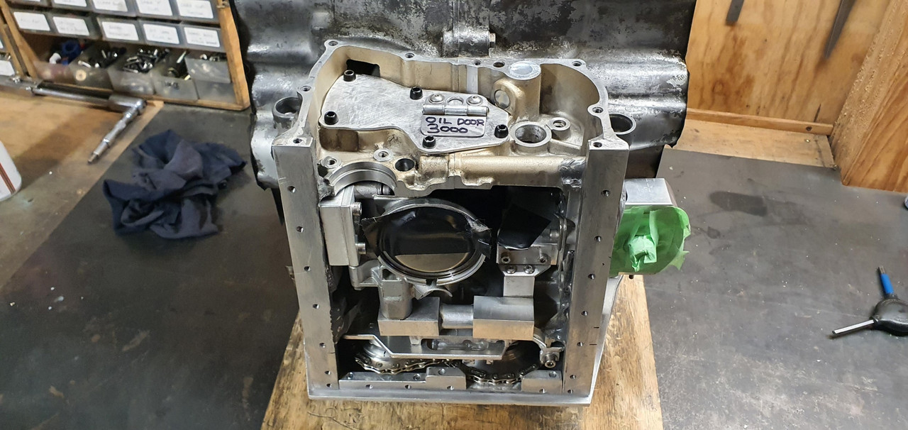
Torqued the heads in place and then moved onto the camshafts/camshaft and follower housings..
In place...
Now I needed to finish the trigger wheels which meant getting them phased in the correct position
I laid out all the bits that go with the cam covers and pulleys.
This alloy bit was damaged from when the original Goldwing bike must have been dropped (I think the engine must have come from a low mileage bike that had been involved in an accident many moons ago)
It wasn't sitting flat and needed a bit of a straighten..
Simple I thought. I'll use the press. I carefully set it up on the press with various bit of metal so I could bend it back straight. I got it pretty good - but it needed just a little bit more...
Bang!
Whoops.
* Pic is taken after I'd already started prepping it to weld.
I preheated it in the oven and then carefully sticthed it back together. Not the nicest casting to weld but it turned out ok and luckily the repairs are not on display..
Welded both sides..
Trigger wheel time. First off I wanted to work out the wire polarity on the oem goldwing VR sensors..
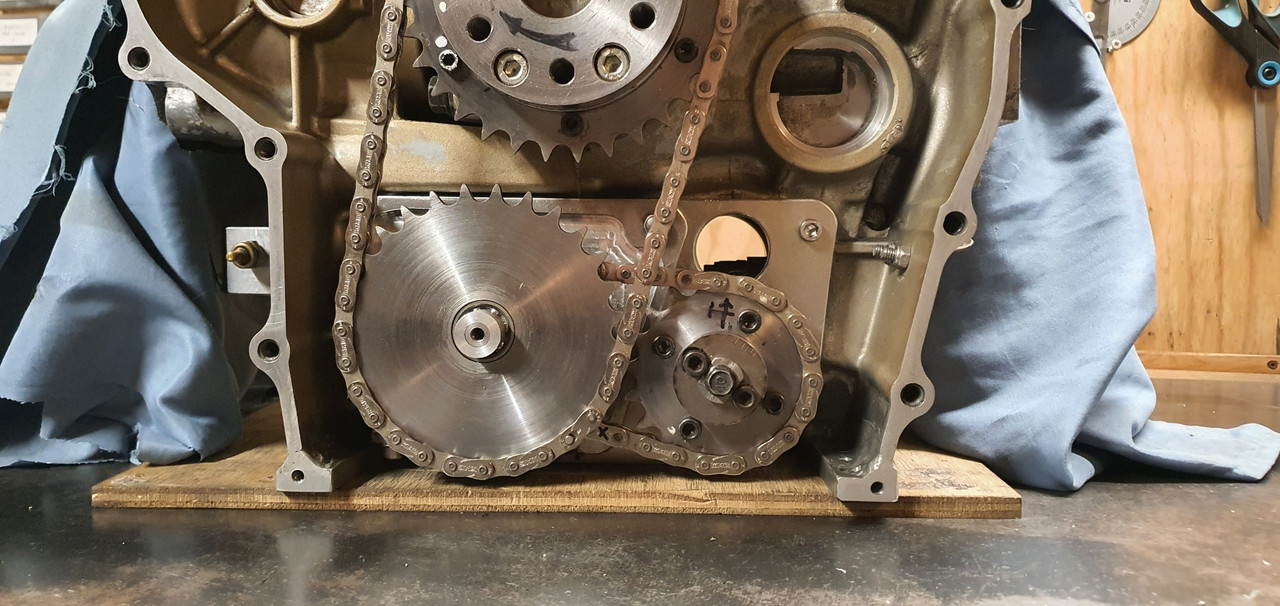
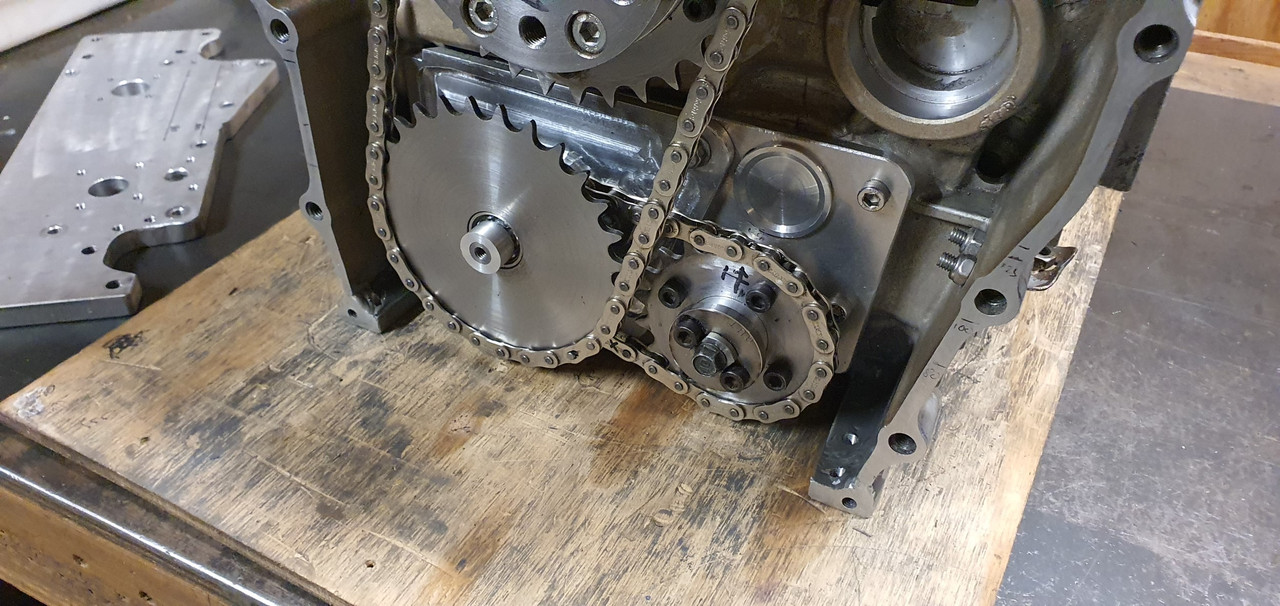
Now I knew the timing marks are good I set up the main crank position trigger wheel in place and marked it. Then welded a stub of steel in place which was cut down to form a key that locates in the cranks keyway.
I doubled checked the megasquirt MS extra build manual and removed the appropriate tooth so creating a 36 - 1 trigger wheel with a 50 degree offset.
Then I fitted the brand new Gates cambelts I had also bought ages ago. Sadly I discovered they are English made which means they'll probably leak..
Now I could setup the camshaft position sensor trigger wheel - needed so I can run the injection mode as fully sequential.
I had made this wheel a while back but had not yet removed the half moon of material. Annoyingly I forgot to weigh the wheel before I removed material. I now had no real accurate way of working out what to mill off the opposite side to balance the wheel out. Balancing it is probably not super critical but considering that at 6000rpm this wheel will be doing 3000 rpm I really wanted to avoid any extra throw out stress on the pulley or camshaft/camshaft bearings.
The final nail in the coffin for this wheel was it slipping in my makeshift rotary table (actually just the mill vice which can be rotated to mill the concentric slot - which I did by hand)
It slipped, the end mill grabbed and became two pieces with a loud bang.
So I made a new wheel. This time I weighed it before removing the halfmoon. Then I was able to mill the exact right amount off to balance it as best I could.
Weighing it before milling out the final weight reduction slots..
Setup in place..
All that sorted I could move on to a fun little job I was looking forward to. Painting the cam covers and sorting out replacements for the old badges.
After a really good clean and some light sanding of the covers, which have been through the wars and have extensive welding repairs due to the same crash I guess, I laid down some primer.
See one repair here...
Due to the fairly rough finish I decided on wrinkle finish paint because it can hide sins and blemishes. I've used this same product to good success on that Mazda V6 I had plonked into my Viva HB so I was pretty confident on getting an OK finish. Covers were warmed up in the sunshine and 3 thick coats were laid down, 5 minutes between each coat.
Once the paint did its magic thing they came up ok. I'm happy.
Now the badges. I was going to try a couple of mates about getting something with the word HONDA 3d printed or machined in alloy but I really wanted to do it all myself and thought about some nice machined ribs to insert.
they turned out neat..
Carefully fixed in place as per original badges with double sided foam tape...
Covers bolted up in place. I'm really happy with the look


.jpg)
.jpg)
.jpg)
.jpg)
.jpg)

.jpg)
.jpg)
.jpg)
.jpg)
.jpg)
.jpg)
.jpg)
.jpg)
.jpg)
.jpg)
.jpg)
.jpg)
.jpg)
.jpg)
.jpg)
.jpg)
.jpg)
.jpg)
.jpg)
.jpg)
.jpg)
.jpg)
.jpg)
.jpg)
.jpg)
.jpg)
.jpg)
.jpg)
.jpg)
.jpg)
.jpg)
.jpg)