Inlet fun over and time to move on to some other jobs. First off was to start on the pipework for the cooling. Like I mentioned a while back the heads are symmetrical and each has a outlet for the hot coolant. So one ends up at the front and one at the back.
Here's the back one...
.jpg)
Both just visible in this shot...
.jpg)
On the bike these were plumbed so they joined up near the middle and went into a thermostat housing and from there to the radiator. But I will be running an electric pump behind the engine so that's where these outlets have to be plumbed towards. I started on the front outlet. I gathered together the bits of pipework from the bike setup..
.jpg)
I chopped them up and using bits and pieces I welded together a pipe for the front. They are very thin- about 1mm so it was a tricky one for my tig skills but I did ok. I'll probably paint them and that'll hide the lumps
.jpg)
Pipe went like this...
.jpg)
.jpg)
Holes = whoops..
.jpg)
Bracket..
.jpg)
And that was all I could do for now as I had used up what bits of the old bends I could. I have ordered some 22mm bends from Aliexpress and so I wait.
Better start sussing out the injection gubbins then. I went into the store room and dug out the box labelled 'electronics' and another full of various sensors I'd been collecting. Blew the dust off them and sort of like xmas day I carefully removed all the goodies within. Laid them out on the work table and this is what I had...
.jpg)
The brains of it all is a second hand Megasquirt 3 with the expansion board. Apart from the faster processor, SD card slot, loads more ins and outs, canbus etc etc it also allows for fully sequential injection. I'll need to change some of the jumper wiring because its setup for a stepper idle valve and a hall sensor on the crank but otherwise its all good.
.jpg)
I have a few VR and hall sensors to try out..
.jpg)
Temp sensors ...
.jpg)
First thing was to plug in my megastim and power it up then test the ecu out. Its all working fine. Its been ages since I have used tunerstudio. Not used it since I sold my Viva.
.jpg)
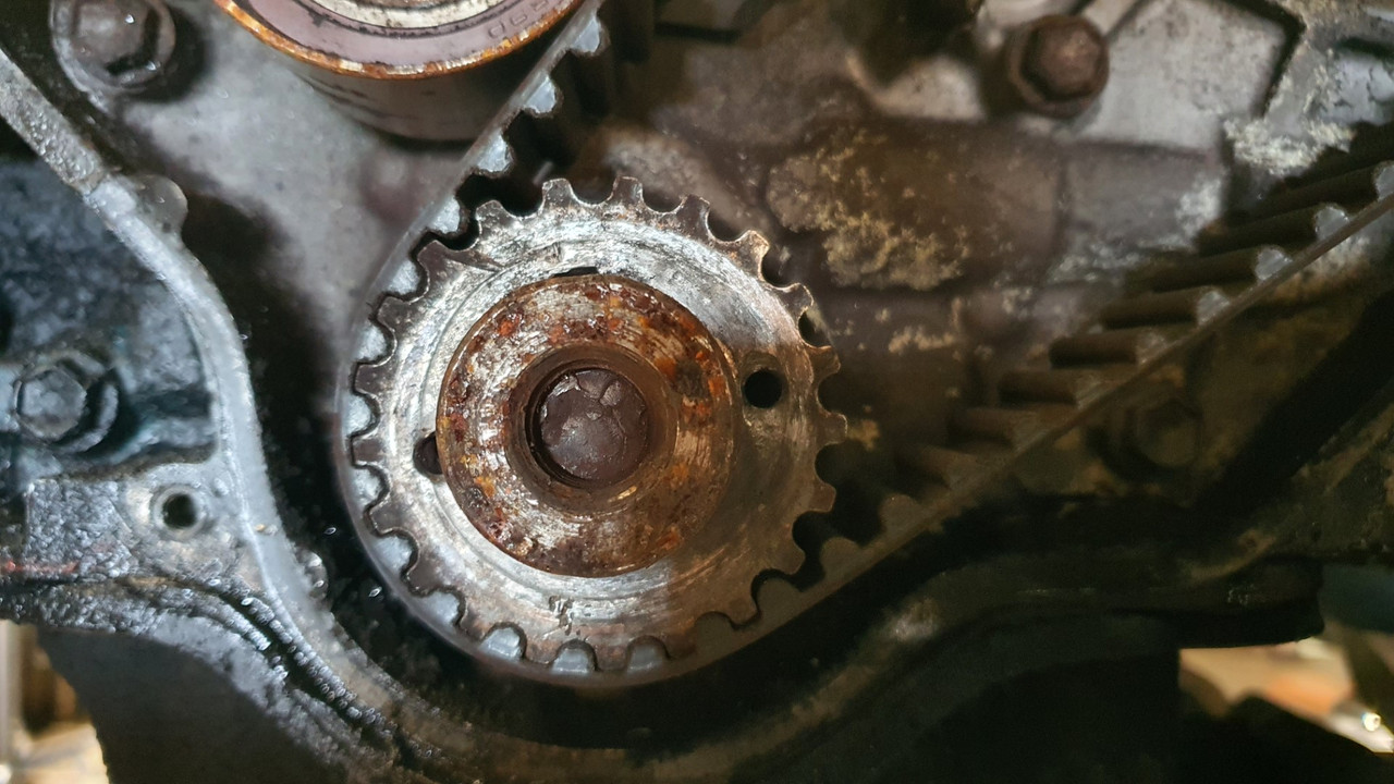
Now time to start on setting up sensors to suit. Starting with the crank sensor. The Goldwing came fitted with a 12-1 trigger wheel and two VR sensors (called pulse generators in bike world) to run the ignition module...
.jpg)
I could have just kept the trigger wheel as is but for better resolution on a full engine management setup it makes sense to go for at least a 36-1 trigger wheel. I knew there would be nothing available even close to fitting my needs so I made one in much the same way as I did for the Viva.
I cut out a disc with the plasma cutter..
.jpg)
Cleaned it up in the lathe and drilled/machined out the bore, ensuring it was perfectly concentric to the bore. The VR sensor needs to have no more than about .020" clearance.
.jpg)
Made a jig for the drill and using the original trigger wheel I was able to mark out the teeth.
.jpg)
I set the jig up with a locator bolt so I was able to turn the wheel one tooth at a time and drill it and then repeat...
.jpg)
Then I carefully cut out up to the holes, gave it a tickle with a file and I had my trigger wheel. I have yet to remove the 'missing tooth' or tig in a nib in the centre that keys to the crankshaft. I'll sort that later.
.jpg)
Now I had to sort out my second sensor wheel, for the cam or 'home' signal. This will be a single tooth or maybe a half moon. I'm not sure and have yet to work out what's best. The MS manual suggests a half moon type (like one long tooth). Other OEM setups just have a single small tooth. Either way I need a sensor to be mounted near one of the cam pulleys.
What seems to be recommended as the better option for the home signal is a hall sensor due to the fact that the camshaft spins at half the speed of the crank and when the engine is being turned over at startup it could potentially be quite a low speed. So low that a VR sensor might not be able to produce enough of a pulse for the ECU.
I had played around with a couple of VR sensors out of interest to see if they might fit in place but everything I had was too bulky or the wrong shape to fit under the cambelt cover...
.jpg)
.jpg)
Anyway- they were VR sensors and not what I wanted. I looked about on googleworld and found a couple of hall sensors that looked like they might work.
Another trip to my local wreckers was called for. I rummaged about in various engine bays and found what I was after in a 2003 Peugeot 307. It was ideal! I grabbed the plug with a length of wire attached. Once home I whipped up a bracket from some thick walled alloy angle, a hacksaw and file and had the sensor fitting where I wanted it.
.jpg)
Once I have decided what type of toothed wheel shape to make I'll be sorting that out.
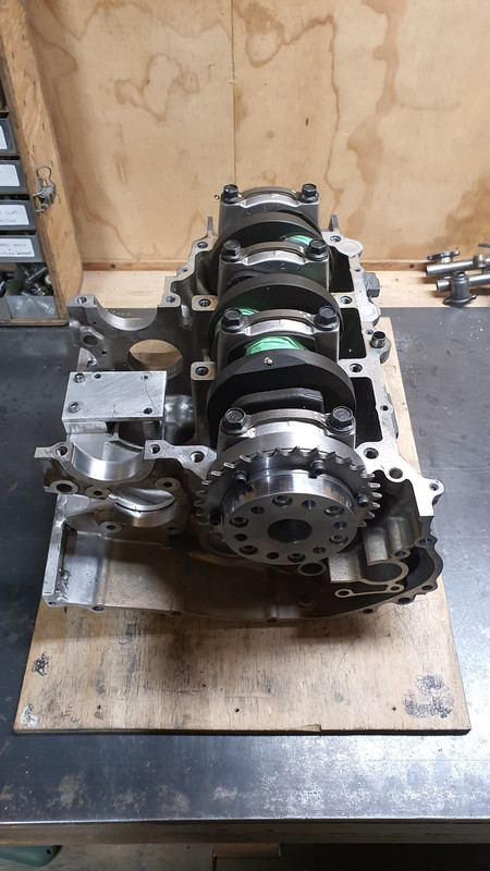
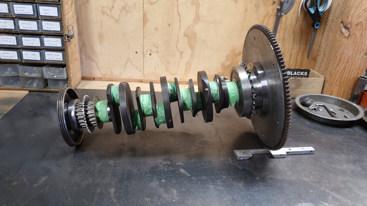
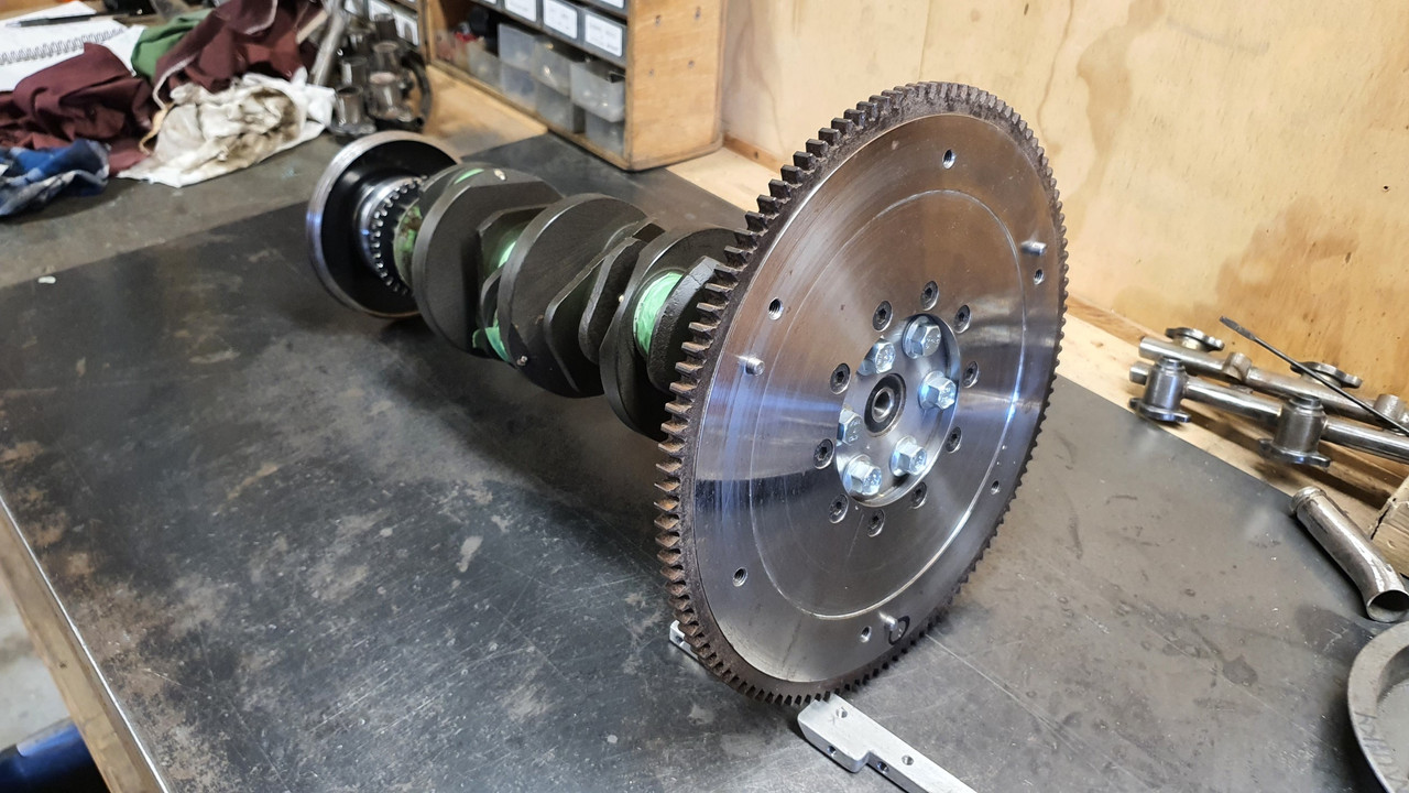
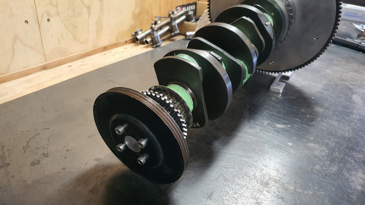
After all this I stripped the whole engine down and removed the crank...
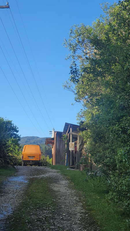
The next day Hannah and I took the imp for a hoon and visited the big smoke, Nelson city, to do some shopping. I'm now sussing out where to get my crankshaft balanced up - without a doubt this is one job that has to be done.
Imp looked great against the blue sky along the promenade in Nelson ...

Here's the back one...
Both just visible in this shot...
On the bike these were plumbed so they joined up near the middle and went into a thermostat housing and from there to the radiator. But I will be running an electric pump behind the engine so that's where these outlets have to be plumbed towards. I started on the front outlet. I gathered together the bits of pipework from the bike setup..
I chopped them up and using bits and pieces I welded together a pipe for the front. They are very thin- about 1mm so it was a tricky one for my tig skills but I did ok. I'll probably paint them and that'll hide the lumps

Pipe went like this...
Holes = whoops..
Bracket..
And that was all I could do for now as I had used up what bits of the old bends I could. I have ordered some 22mm bends from Aliexpress and so I wait.
Better start sussing out the injection gubbins then. I went into the store room and dug out the box labelled 'electronics' and another full of various sensors I'd been collecting. Blew the dust off them and sort of like xmas day I carefully removed all the goodies within. Laid them out on the work table and this is what I had...
The brains of it all is a second hand Megasquirt 3 with the expansion board. Apart from the faster processor, SD card slot, loads more ins and outs, canbus etc etc it also allows for fully sequential injection. I'll need to change some of the jumper wiring because its setup for a stepper idle valve and a hall sensor on the crank but otherwise its all good.
I have a few VR and hall sensors to try out..
Temp sensors ...
First thing was to plug in my megastim and power it up then test the ecu out. Its all working fine. Its been ages since I have used tunerstudio. Not used it since I sold my Viva.
Now time to start on setting up sensors to suit. Starting with the crank sensor. The Goldwing came fitted with a 12-1 trigger wheel and two VR sensors (called pulse generators in bike world) to run the ignition module...
I could have just kept the trigger wheel as is but for better resolution on a full engine management setup it makes sense to go for at least a 36-1 trigger wheel. I knew there would be nothing available even close to fitting my needs so I made one in much the same way as I did for the Viva.
I cut out a disc with the plasma cutter..
Cleaned it up in the lathe and drilled/machined out the bore, ensuring it was perfectly concentric to the bore. The VR sensor needs to have no more than about .020" clearance.
Made a jig for the drill and using the original trigger wheel I was able to mark out the teeth.
I set the jig up with a locator bolt so I was able to turn the wheel one tooth at a time and drill it and then repeat...
Then I carefully cut out up to the holes, gave it a tickle with a file and I had my trigger wheel. I have yet to remove the 'missing tooth' or tig in a nib in the centre that keys to the crankshaft. I'll sort that later.
Now I had to sort out my second sensor wheel, for the cam or 'home' signal. This will be a single tooth or maybe a half moon. I'm not sure and have yet to work out what's best. The MS manual suggests a half moon type (like one long tooth). Other OEM setups just have a single small tooth. Either way I need a sensor to be mounted near one of the cam pulleys.
What seems to be recommended as the better option for the home signal is a hall sensor due to the fact that the camshaft spins at half the speed of the crank and when the engine is being turned over at startup it could potentially be quite a low speed. So low that a VR sensor might not be able to produce enough of a pulse for the ECU.
I had played around with a couple of VR sensors out of interest to see if they might fit in place but everything I had was too bulky or the wrong shape to fit under the cambelt cover...
Anyway- they were VR sensors and not what I wanted. I looked about on googleworld and found a couple of hall sensors that looked like they might work.
Another trip to my local wreckers was called for. I rummaged about in various engine bays and found what I was after in a 2003 Peugeot 307. It was ideal! I grabbed the plug with a length of wire attached. Once home I whipped up a bracket from some thick walled alloy angle, a hacksaw and file and had the sensor fitting where I wanted it.
Once I have decided what type of toothed wheel shape to make I'll be sorting that out.
After all this I stripped the whole engine down and removed the crank...
The next day Hannah and I took the imp for a hoon and visited the big smoke, Nelson city, to do some shopping. I'm now sussing out where to get my crankshaft balanced up - without a doubt this is one job that has to be done.
Imp looked great against the blue sky along the promenade in Nelson
...

.jpg)
_(Large).jpg)
_(Large).jpg)
.jpg)
.jpg)


.jpg)
.jpg)
.jpg)
.jpg)
.jpg)
.jpg)
.jpg)
.jpg)
.jpg)
.jpg)
.jpg)
.jpg)
.jpg)
.jpg)
.jpg)
.jpg)
.jpg)
.jpg)
.jpg)
.jpg)
.jpg)
.jpg)
.jpg)
.jpg)
.jpg)
.jpg)
.jpg)
.jpg)
.jpg)
_(Custom).jpg)
_(Custom).jpg)
_(Custom).jpg)