|
|
|
Mar 13, 2014 20:07:03 GMT
|
OK as well as the advice above ref where and how to weld the panel on I have spent the afternoon making a template of the second piece to be made. I have read through this thread on making templates and repair pieces but could not reliably take measurements from the piece that needs to be repaired and transpose them onto sheet metal so not knowing any other way I decided to make a cardboard template. First I marked the main curve by placing a piece of cardboard at right angles to my first repair plate clamped in place then I transferred this curve onto another piece of cardboard that would be used to make the main template. I then marked the entire top curve onto my template and used this as a start line to mark measurements taken from the piece to be replaced. I then made a few folds in my cardboard template and started to fit it into the recess of the panel to be replaced, making the template did demonstrate the metal would react on the curves, on the upper curve the cardboard needed to be cut and overlapped and on the bottom it had to be cut and left gaps. So to make these edges i'll do the same with the metal piece and weld the cuts?? Or attempt to shrink (fold in) the top edge and stretch the underside edge. 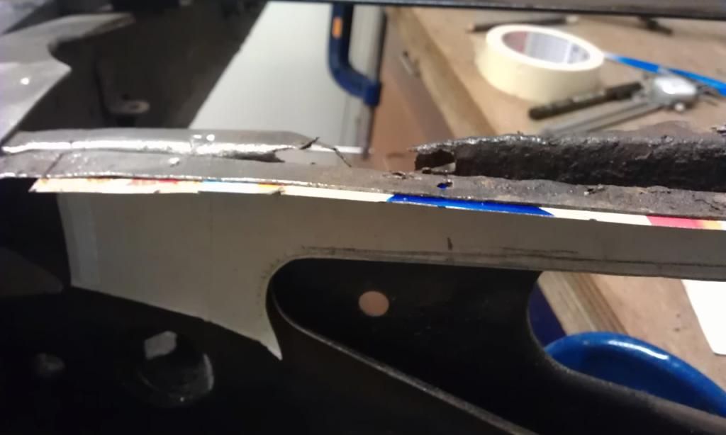 The template above does push back and almost hide the top edge. Basically I have ended up with a template of the inside measurements of the panel to be replaced, this started to confuse me as to how to correctly transpose these measurements onto my sheet metal and end up with a repair piece that would fit? My thoughts were that if i did not make any allowances for this all I would end up with is a repair panel that would fit inside the piece being repaired and therefore end up too small!!! Here's the template laid out on my sheet metal: 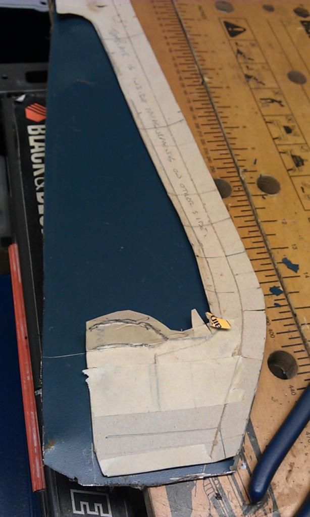 I started to mark out the rest of the panel but stopped once I realised my problem. I am know going to read through the relevant sections of this thread and see if I can figure it out? HELP PLEASE!!! |
| |
|
|
|
|
|
|
|
Mar 17, 2014 21:50:38 GMT
|
OK - I have started to form the second repair piece of my Subframe repair, bending the straight folds was simple: 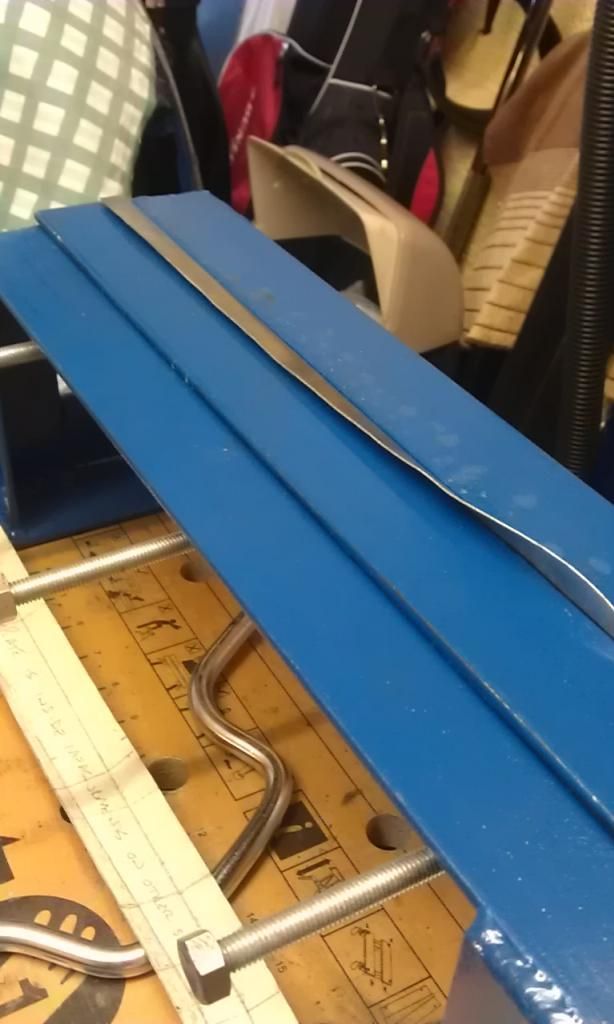 Trying to bend the curved folds however proved a bit trickier, I could not do it in my bender due to the size of the panel, maybe if I had started with the curved folds first it may have worked but I needed to get the straight folds done to ensure the curved folds were correct as the piece I have cut off had already been repaired and was distorted in that area?@?@??@ First I cut the folds to avoid having to shrink along the curve, i'll weld the cuts, from the inside and grind. 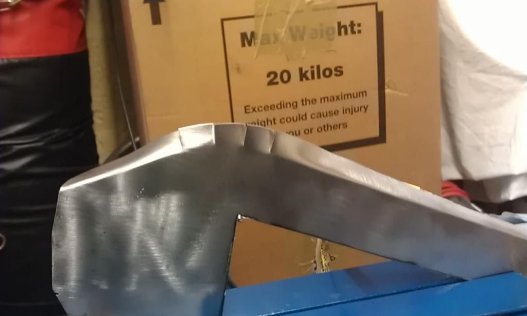 Not knowing how else to bend these folds I managed to use one of the Dollies from my recently acquired panel beating set, luckily the curve of the dolly was about the same radius as the piece being repaired: 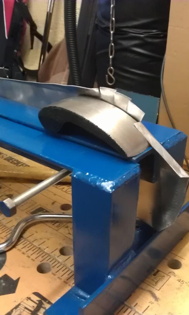 Any tips on doing this better for the next two? I then measured and marked the bottom fold and managed to start it off in the bender but due to the close proximity of the two folds could only bend to about 45 Degrees. I had to then clamp the piece to my workbench and using a piece of scrap sheet about 5mm thick wedged into the fold I managed to tap the remainder of the fold. Sorry no pics of how I did it but again any tips on bending close folds would be appreciated (The folds in the picture below to the RH side of the Mole Grips on the left). Here's the panel so far clamped into place: 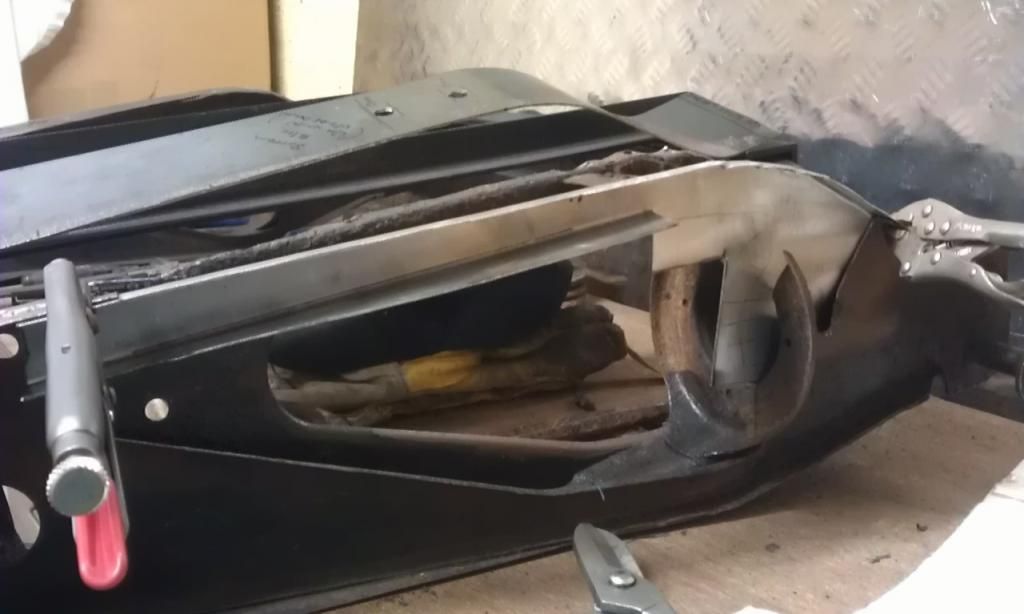 You'll also notice that the metal on the top curved fold where it has been cut overlaps itself, this is because all I did was cut a line with a pair of snips. Should I cut a small 'V' to ensure that the metal lines up and then weld the gap? Now that I have the end folds done I am going to trim and joggle the ends so that the repair piece can fit into its correct position at each end before I tackle the complicated curved and shaped section? |
| |
|
|
|
|
|
Mar 18, 2014 21:18:35 GMT
|
Ok back at it this morning, I snipped the excess from the cuts in the radiused fold and got a nice smooth curve ready for welding. Before I welded the actual repair piece I did some test (a) because I haven't used my Mig for a while and (b) to get the settings right before I tackled the actual piece. Here are the test welds: 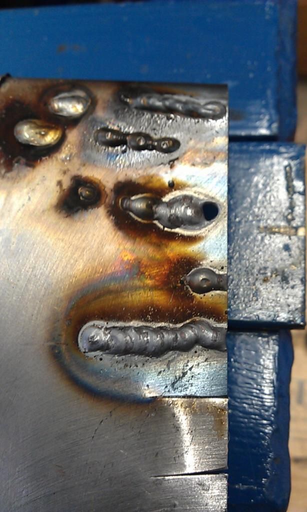 I used a piece of copper bar (flattened pipe) clamped on the underside to help stop burning the edges and I also started from the outside edge working inwards as demonstrated by tonybmw in this thread. 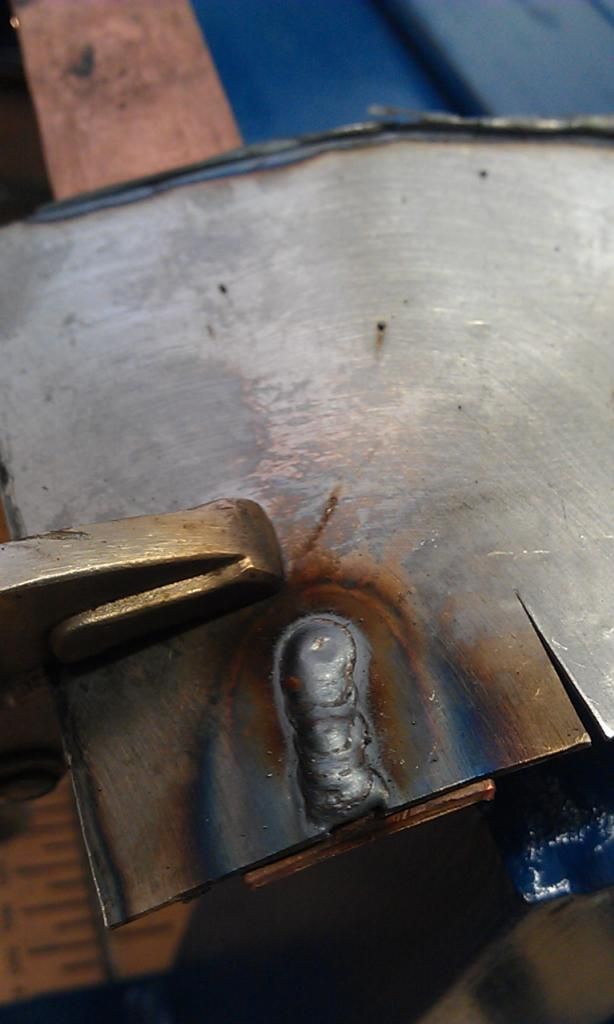 The bottom weld seems fine once I got the settings right on my Clarke 160EN (Power Min 1 Wire Speed 7), what do you guys reckon? penetration was OK too: 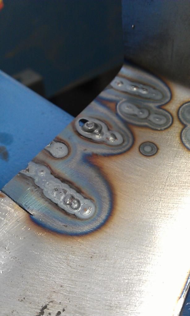 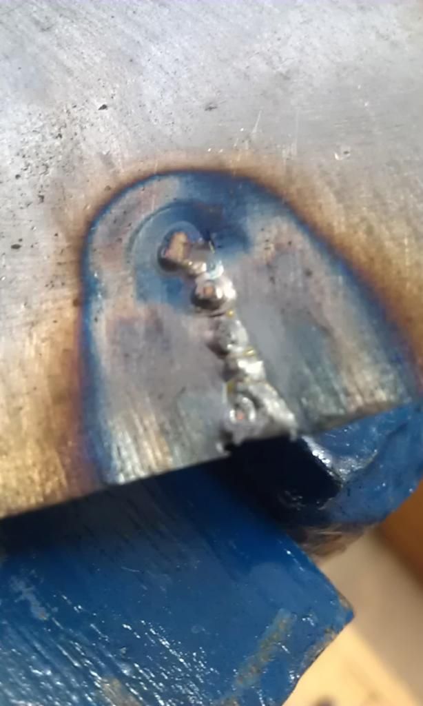 After gently cleaning up my repair panel with a wire brush drill attachment on slow speed I then tackled the actual welds, I did the outside ones first and then the middle ones to avoid distortion: 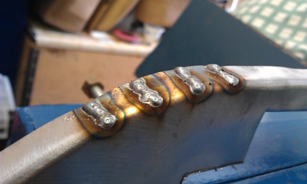 These seem a little cooler (as in cold) than the last couple on the test piece and the penetration could have been better, I may have been a little too cautious and going a little fast to avoid burning through - any expert advice? 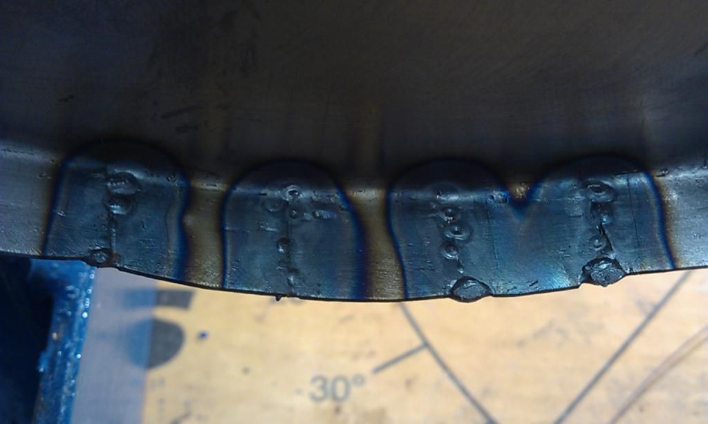 Should I weld the underside on this one just in case? Here's a close up after they have been cleaned up so you can get a better look: 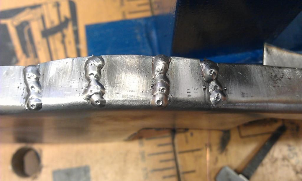 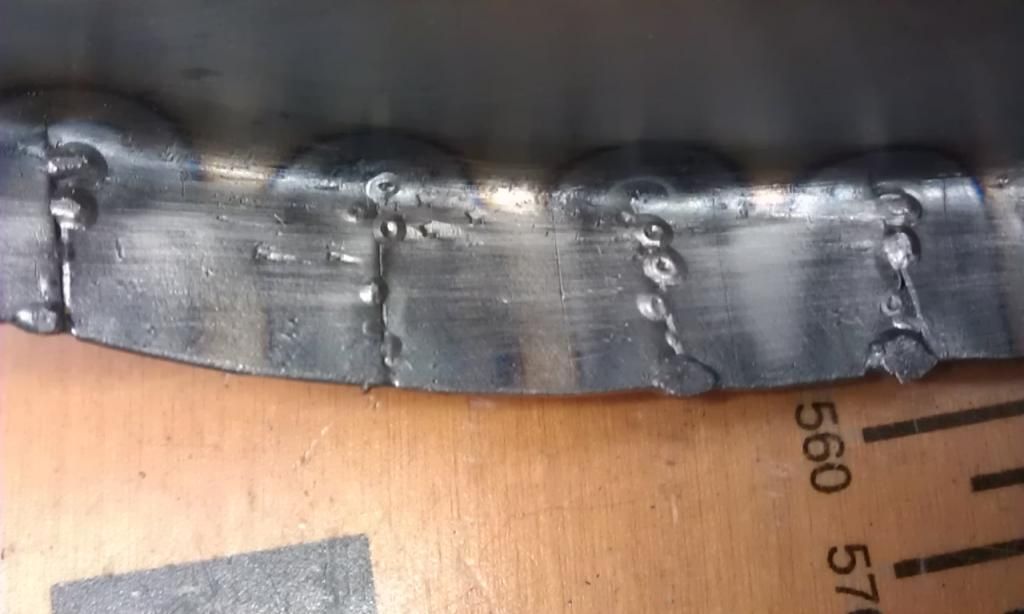 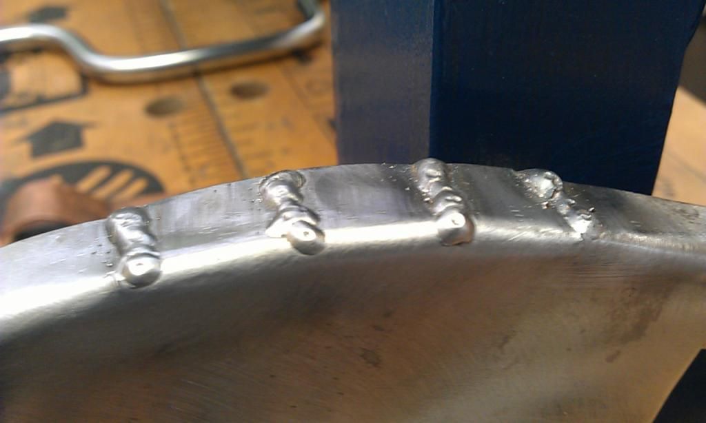 I also have a slight problem with my welder in that the wire feed spool / motor spindle is very slightly off centre which means on I get an annoying stop start on the wire feed which is exaggerated with a slow wire speed to a stop - start - stop!!! On a higher setting its not so bad. I posted about this on the Mig Welding Forum many moons ago and nearly bought a new motor but not sure if it was a common fault. I think I managed to get it to a manageable state by tightening up the grip on the feeder, i'll try to tighten it up again. Here's the repair piece test fitted again, the curve seems OK: 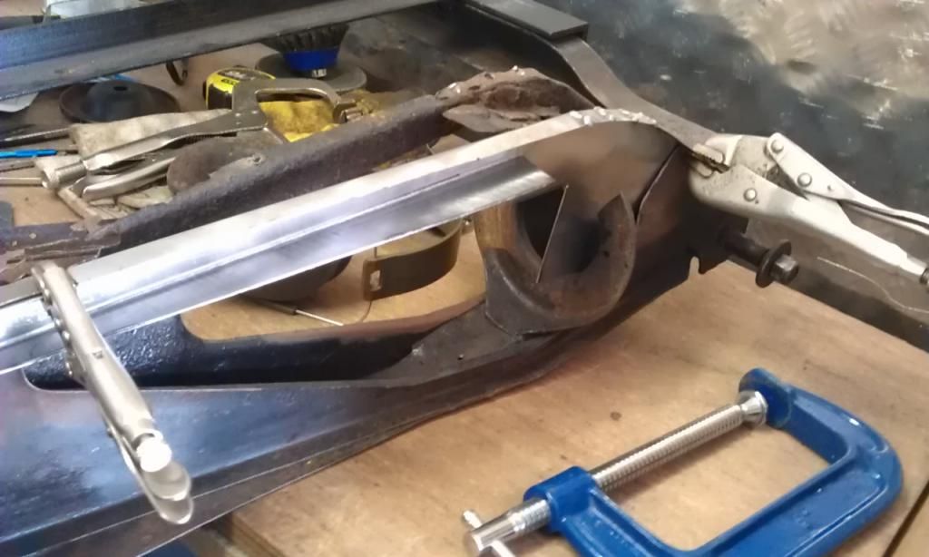 Slow going but satisfying none the less - good job I'm not paying by the hour!!! Any advice would be most welcomed More later :-) |
| |
|
|
|
|
|
Mar 19, 2014 19:29:28 GMT
|
I managed to do the underside welds of my second repair piece, had a job getting the setting right but got there in the end. Burnt an edge rushing but repaired it using the copper trick ;-) Here's the finished article (well at least the radius is finished): 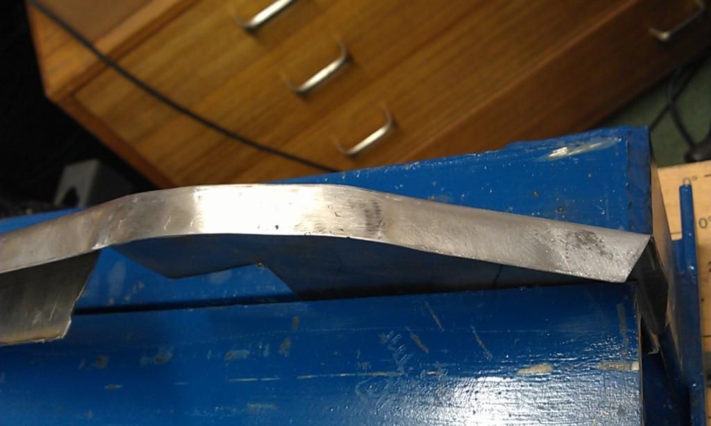 Here's the underside - what's the best way of cleaning this up, at the mo I only have some flap discs for my angle grinder and some hand files. 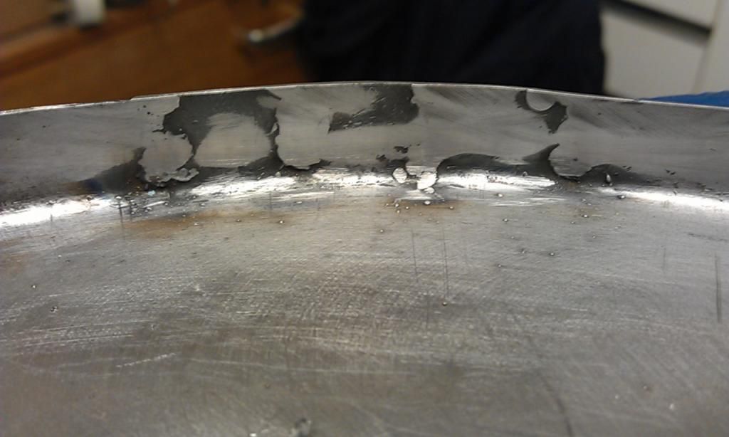 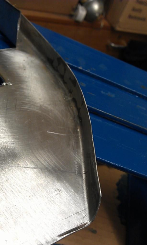 Its a right angled bend and I need to get in the corners, will I have to invest in a power file? Or dremel or are there small attachments for my drill? |
| |
|
|
|
|
|
Mar 21, 2014 12:23:58 GMT
|
OK - I have started to form the second repair piece of my Subframe repair, bending the straight folds was simple: Only thing I would say is to bend more gradually as you might introduce stretching. In the photo (if I've quoted properly) you can see that at one end you've done almost the whole 90 degree fold, and at the other end there's none, but that puts a stretch in the flange section in the middle which can lead to the panel twisting. Do the whole length about 10 degrees at a time and it seems to help. Trying to bend the curved folds however proved a bit trickier, I could not do it in my bender due to the size of the panel, maybe if I had started with the curved folds first it may have worked but I needed to get the straight folds done to ensure the curved folds were correct as the piece I have cut off had already been repaired and was distorted in that area?@?@??@ Yes, often you have to think the whole job through to make sure that you don't end up blocking access and making the job harder. It's just experience, you'll remember next time. I've lost count of the number of jobs I've done on my project that would have been simpler if I'd done them in a different order. I then measured and marked the bottom fold and managed to start it off in the bender but due to the close proximity of the two folds could only bend to about 45 Degrees. I had to then clamp the piece to my workbench and using a piece of scrap sheet about 5mm thick wedged into the fold I managed to tap the remainder of the fold. Sorry no pics of how I did it but again any tips on bending close folds would be appreciated (The folds in the picture below to the RH side of the Mole Grips on the left). As you do more of this stuff, you'll gather scraps of stuff to put in the vice or bender to help make these closer bends. It's just a case of looking at it from all angles then figuring out what you can use to extend the reach or get into that corner. A straight bender isn't the cure for everything, bits of scrap angle iron and bar can come in very useful. You'll also notice that the metal on the top curved fold where it has been cut overlaps itself, this is because all I did was cut a line with a pair of snips. Should I cut a small 'V' to ensure that the metal lines up and then weld the gap? That's correct - because the metal in that section would be smaller (which is why you would have needed to shrink it if you'd folded without the cuts) you have to remove bits of it. I sometimes do what you've done, then fold it, then use a hacksaw to cut along the overlap, to make sure I haven't cut out too much of a 'V' shape. |
| |
|
|
|
|
|
Mar 21, 2014 21:42:08 GMT
|
Droopsnoot - thanks for the tips. OK now onto the next part of the second repair piece, I need some advice on fabricating this part of the panel: 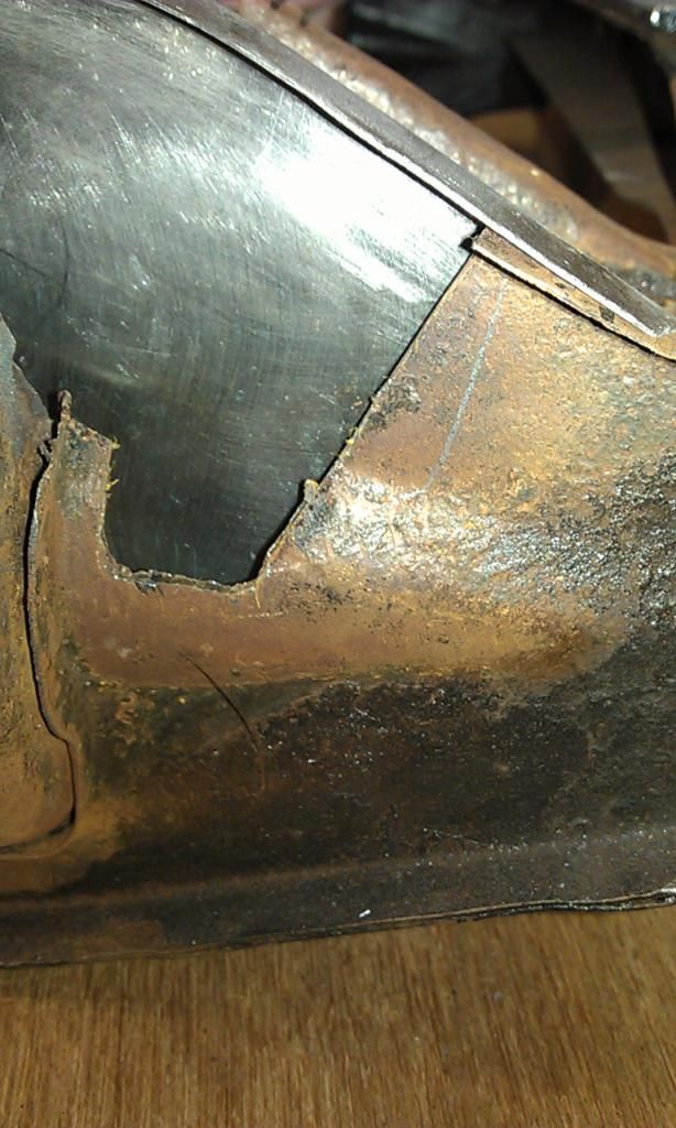 I will be completing the cut at the bottom. The bottom of the repair needs to have a curved fold, on the left hand side has a right angle fold which is the vertical curved piece to the left of the picture. Here is a picture of the opposite side (which also will be replaced) to give you and idea of what the panel needs to look like: 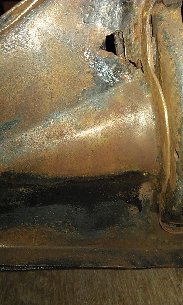 Heres my idea: 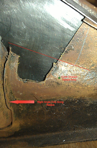 Option 1. One idea I have is to make an initial fold along the red line and form the radius of the cone using a round bar as a guide. After the radius has been formed I was then going form the right angle fold but as this will now be along a curved edge I will have to cut one or two V shapes bend the fold and then weld up the gaps. This option will ensure that the fold remains vertical. Option 2. The second idea was to make the fold along the red line but then also make the vertical fold and then stretch the metal in the second fold in an attempt to create a curve however, this will thin the metal along the fold and it would be difficult to create the correct cone shape. What do you guys reckon on how to tackle this? I am also going to joggle the right hand edge and bottom as there is enough room on the inside (hopefully) to lap weld. |
| |
|
|
|
|
|
Mar 24, 2014 21:12:21 GMT
|
I sort of did a mix of the two ways that were offered, I made the straight fold at the top of the cone, then I made the 90 degree fold and tried to stretch the metal to form the cone, it started to shape but in the end I had to make some cuts in the fold and used a large piece of metal tubing to complete the shape. I then cut the repair panel to fit using a mix of joggled edges for lap welding and end on end joints for butt welding. Made a few errors along the way but nothing that cannot be fixed, could have been better but not bad for a first real effort. I'll post some pics tomorrow. Here's where I am so far: First after re-measuring I marked up the panel and made the initial fold at the top of the cone: 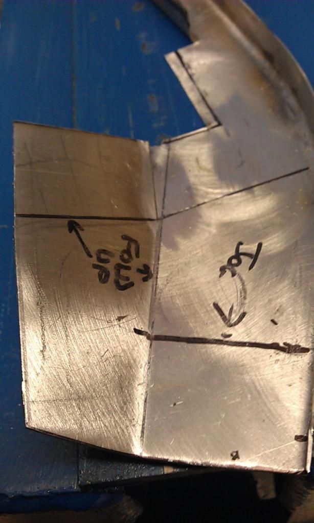 Then I made the 90 degree fold and tried to stretch the edge to form the cone, I had also made one cut before I made the 90 degree fold (first possible mistake I think: 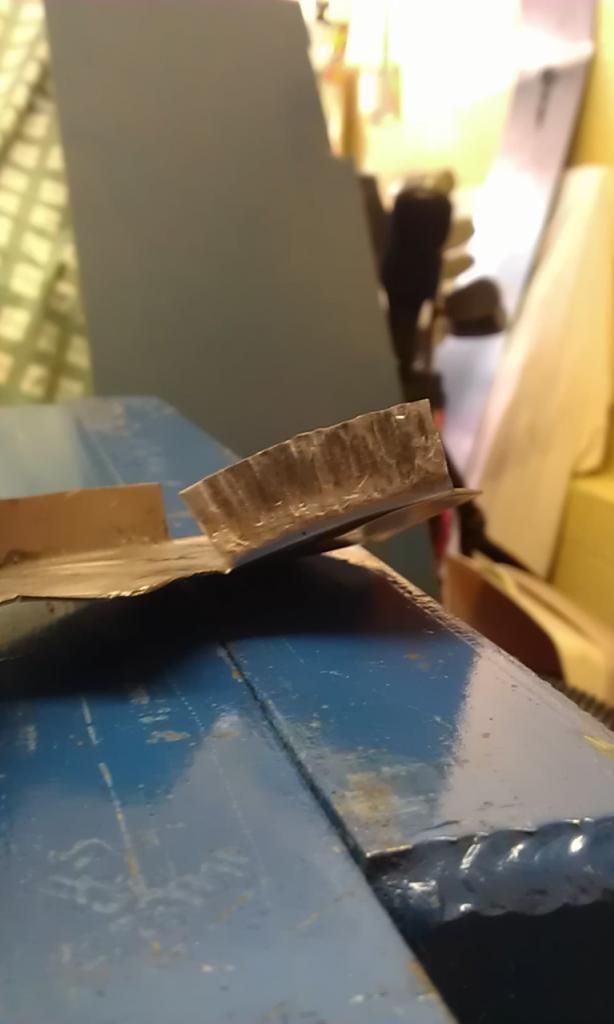 You can see it sort of wanted to form but not enough so I introduce a large metal tube: Two complete the cone shape I had to make another cut (poss another mistake) and then using a piece of bar forced down by hand / body weight I then completed the other folds with a light weight hammer, I also introduce more cuts rather than shrink the metal however I made a few boo boos (another mistake) 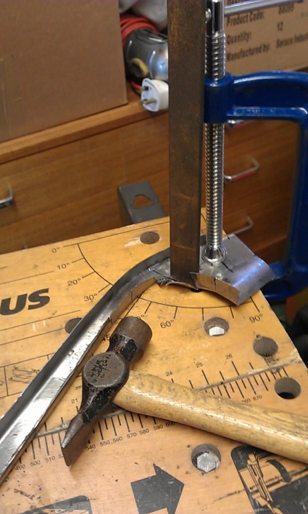 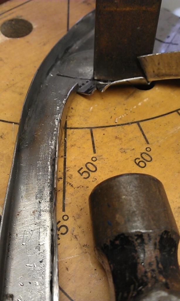 All the cuts however can be welded up so its not the end of the world, if I had been a little more bold and cut the underside fold to the correct size before it was folded I may not have needed the cuts but I didn't want to leave the folded edge too small, still everyday is a learning day!! Here's the panel being test fitted before the joggled edges and but edges had been introduced on the left hand side: 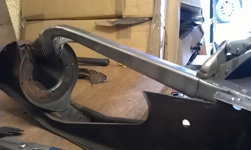 Here's a nice pick of the left hand side once the joggles and but edges had been marked and cut, I decided on a mix of joggled edges and butted edges to improve strength? ![]() 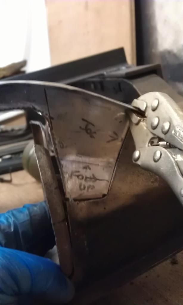 The top R/H edge and bottom edges are joggled and the R/H edge of the cone is a butt (I couldn't work out how to joggle on a radius without flattening the curve?@?@? And finally here is a close up showing the horrendous mess I made of the underside internal curved folded edge: 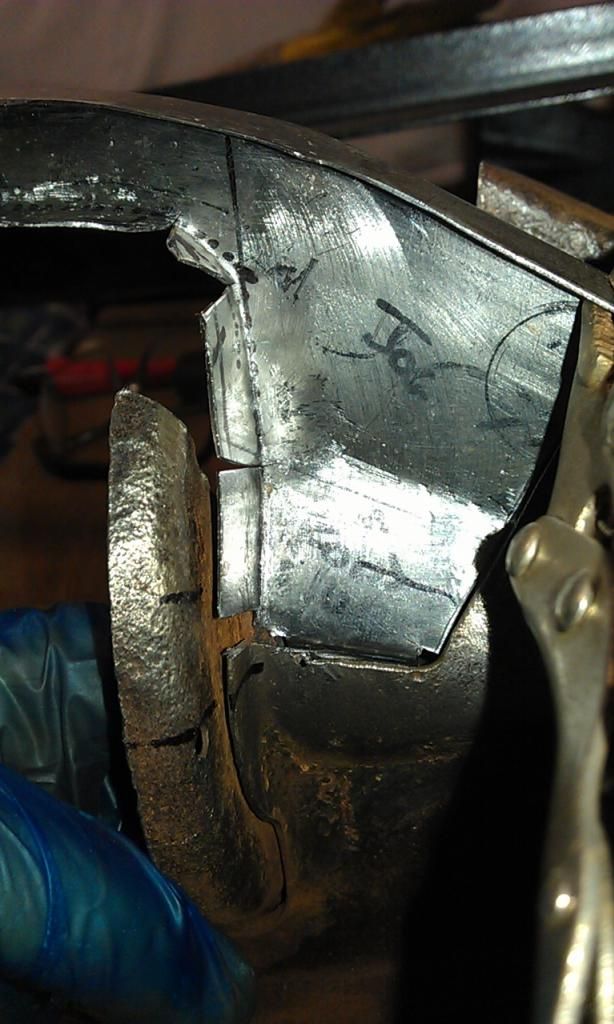 The panel itself is a pretty good fit, its just the folded edge that I messed up!!! |
| |
|
|
|
|
|
Mar 28, 2014 20:06:59 GMT
|
I am now making the repair piece for this area: 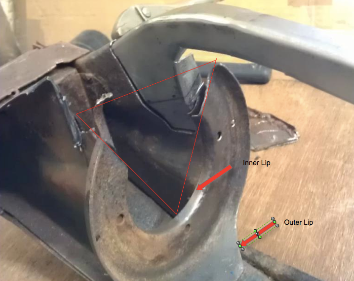 First I started by measuring the area to be repaired to make a template, I used the intact bottom area which is a mirror image: 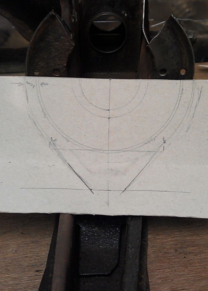 This template turned out incorrect, I had to make another one but you get the idea. I then transferred the measurements to a piece of 2mm steel: 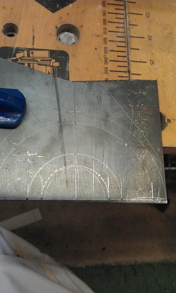 I cut the plate down first and did the first bend in my folder: 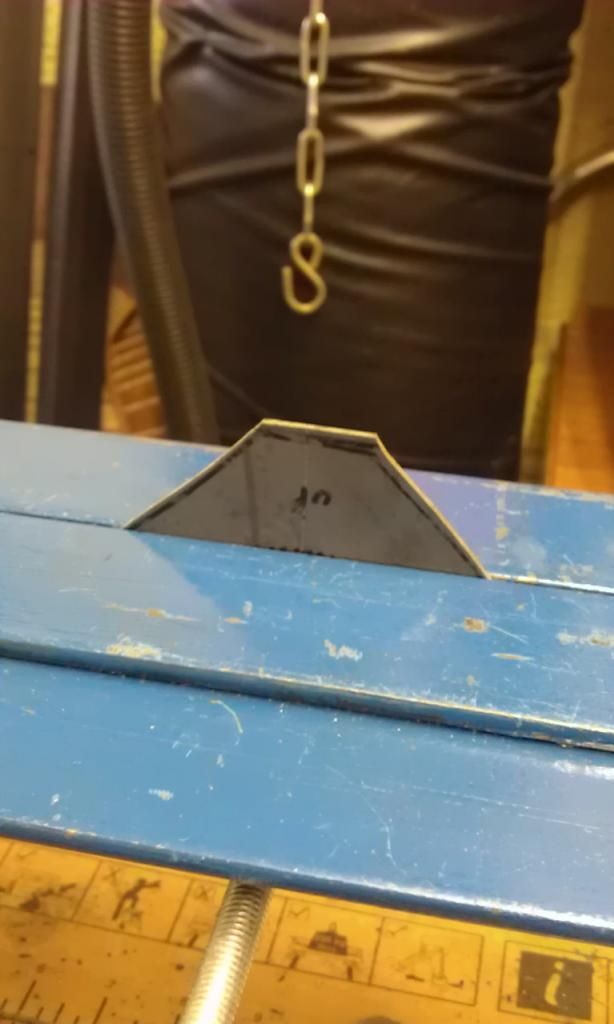 Form advice in this thread I new I would have to make the bends evenly and in small stages, once I did the first folds I then trimmed a piece of 4mm bar so that it had a radius'd edge the same as the radius of my piece to be bent. Using this held in place with a G Clamp I started to slowly apply the bends. To get better leverage I also placed the piece sideways in my bender with this 4mm piece clamped against my panel: 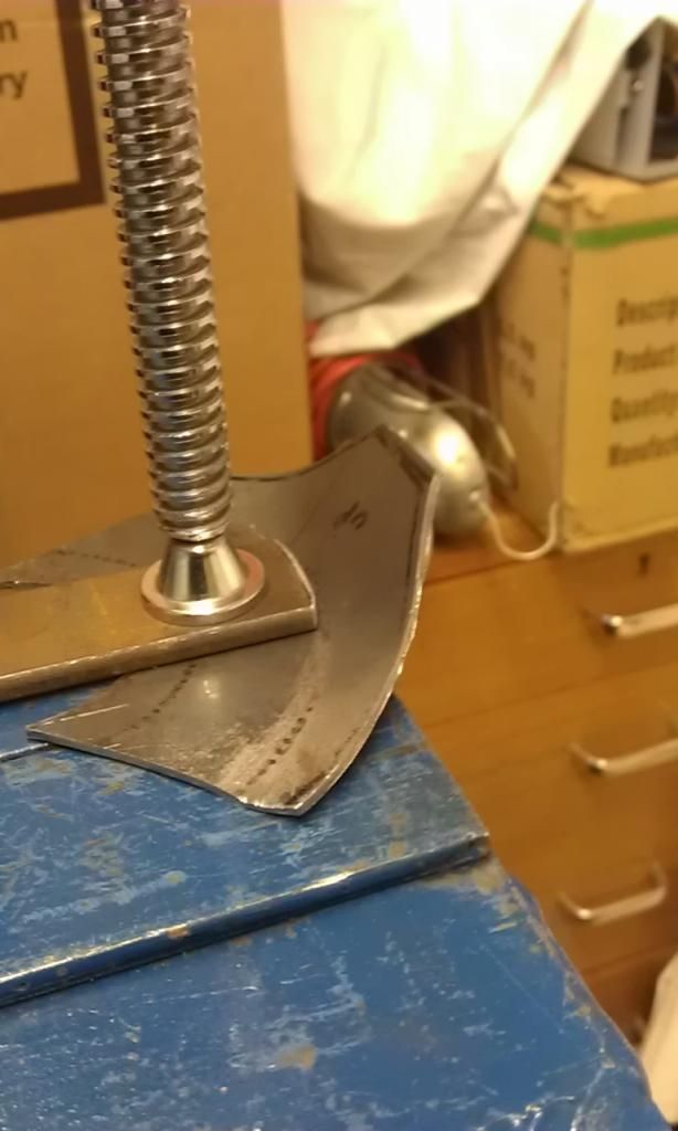 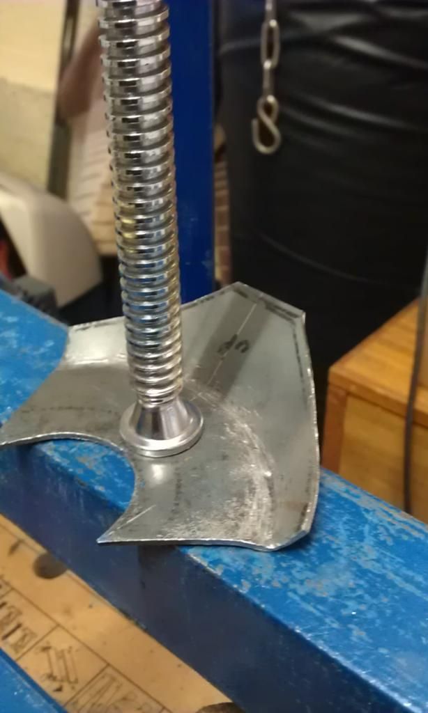 Slowly but surely the fold is forming, however as this metal is a lot harder to form and needed a lot more beating I managed to shear the welds on two of my captive nuts on my bender. I also kept having to hammer flat the area where the clamp is in the above pic as making the folds is trying to pull the flat area out of shape. I am trying to make this piece without having to cut and weld so its slow going but it looks like it will form without having to put a shrink in the edge?? The actual piece I need will be smaller than this but I did not want to cut it to fit before I had formed the correct shape. |
| |
|
|
|
|
|
Mar 29, 2014 19:48:21 GMT
|
More bashing today.............. And after a lot of work here it is: 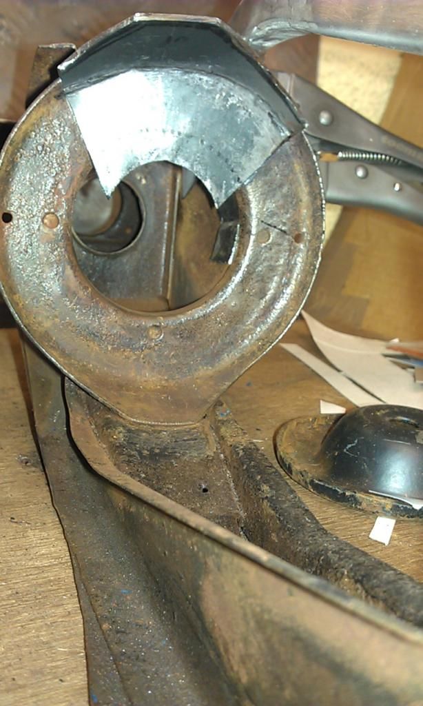 Just got the last fold, the internal one, which hopefully shouldn't be too difficult? |
| |
|
|
|
|
|
Mar 31, 2014 21:06:52 GMT
|
So after another half day in the garage I managed to complete the circular repair piece (less a small amount of minor adjustment before welding) I struggled at first to do the internal bend as I could not find a way of holding it in my bender or clamps to be in a position to fold it. In the end I managed to use part of the subframe as a pattern. Its the rear rubber cone that came off when I removed the trumpets, I think it was very poorly spot welded onto the piece that I am now repairing? Anyway using it as a template held together using 2 x G Clamps I started the fold. 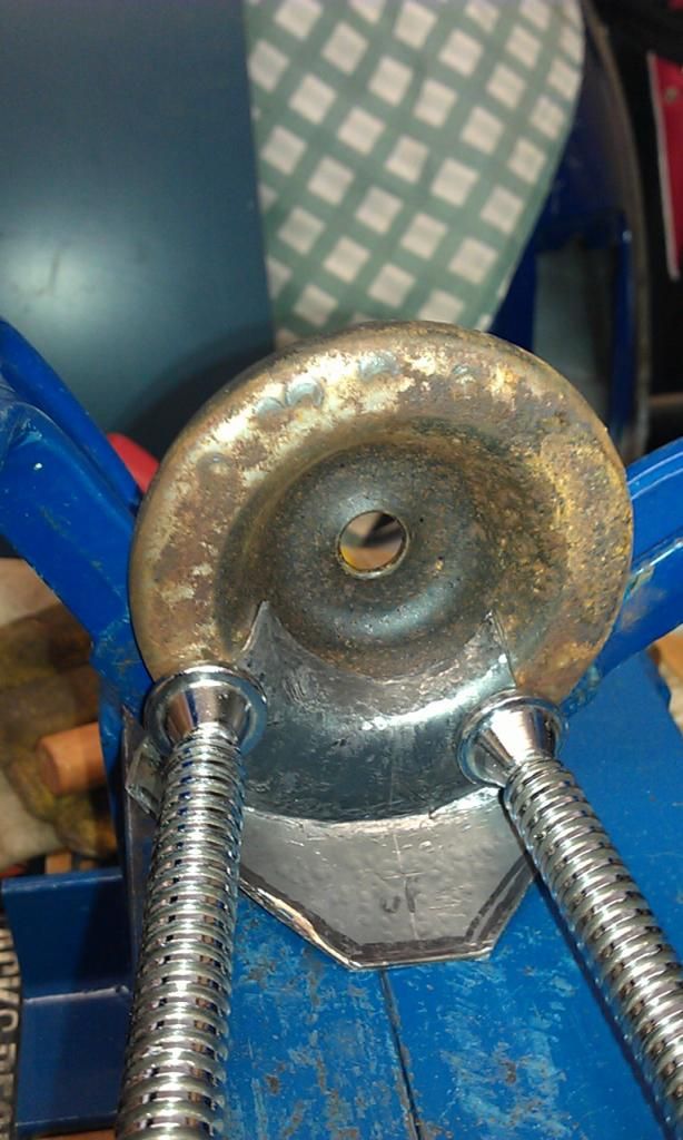 When I fitted it in place the diameter was slightly out but using my vice I managed to bring it in line, its not quite right but it will be hidden behind the the piece used as a template above: 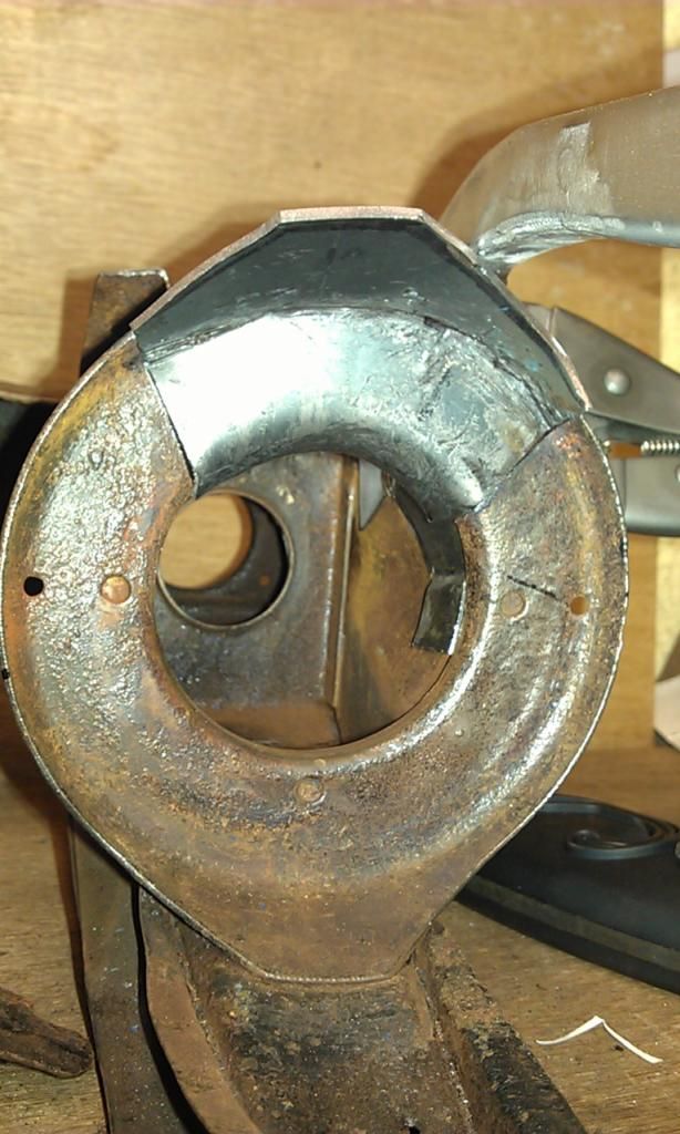 I also had to re-do about 15 - 20mm of the top RH edge external fold as it too was out of kilter so apart from trimming down the excess edges and a little fine tuning its ready to weld in place. I have to be careful however after I have fabricated all of the pieces for this side ensuring that I weld them in the best order otherwise I will find it hard to dress the welds where dressing is required. The piece above will probably be last to be welded? When I weld the circular piece which is 2mm thick I clean up the edges of the existing rusty coloured piece above and as advised i'll bevel the edges of both the repair piece and the existing piece that it will be welded to. To be honest I should have cleaned up the existing piece first in case cleaning it causes my repair piece to not fit as snug!! (lesson learnt for next time). To complete this side I have two pieces left to make, the LH main support (The RH one was the second piece I made) and the internal support piece that the circular piece I have just made sits on, you can see the intact one at the bottom of the pic above, its located between the two main spars. |
| |
|
|
|
|
|
|
|
|
|
Spent a couple of days over the weekend making the second main spar, this time using some of the advice from this and the Retrorides thread, I thought i'd try and form the radius folds without reverting to cutting and welding. Sorry no photos of the stages but I did make a video (Sad I know) its not great quality and needs a little editing but if anyones interested i'll post it on You Tube for a laugh!!! Anyway the results were pretty good, I managed the underside radius without any cutting and only had to make one cut in the topside radius, heres the end result:  Sorry no pic from the other side, my joddled edges are not great (nearly bought an edge setter from Machine Mart, maybe I will soon :-) Here's all three parts in place (not yet welded):  Only one more small piece to make for this side then it can be welded up. When its welded this area will be enclosed: 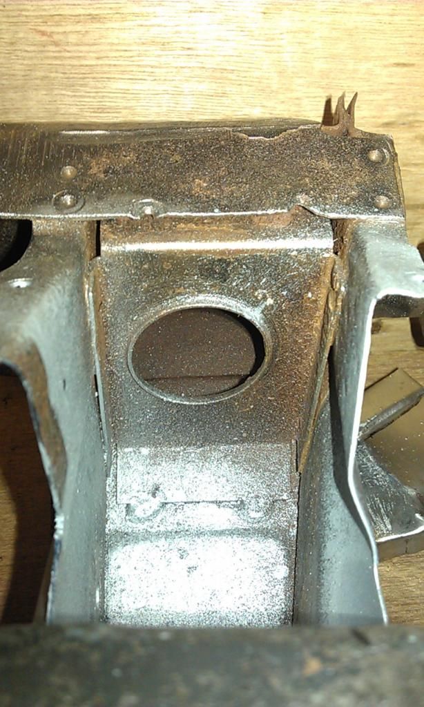 I'm not going to be able to clean it down to bare metal and still undecided (financially) on Acid Dipping / Galvanising the finished article, in case I decide to NOT galvanise and opt to POR15 the subframe should I bung some Hammerite KRUST in this area and coat with Red Oxide or U-POL Weld Through Primer? I already put a bit on in this pic on areas that I could clean up. |
| |
|
|
|
|
|
Apr 10, 2014 19:51:39 GMT
|
In order to fabricate the last piece needed for the side I have been working on I had to start welding in my repair pieces, quite an anxious time as having successfully made the repair pieces the last thing I wanted to do was screw them up welding them in. Here's the circular repair welded in place: 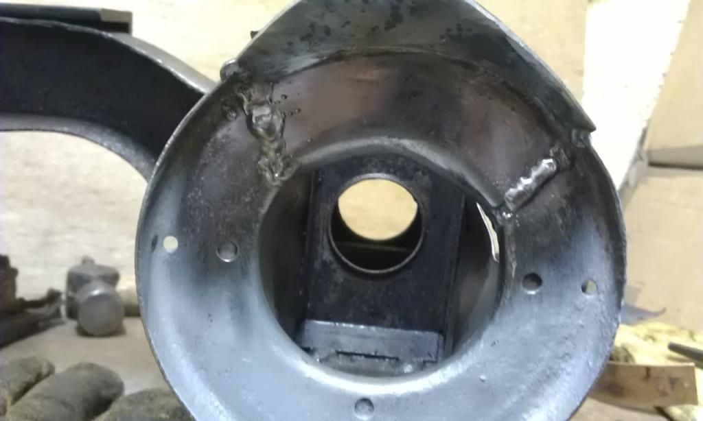 Heres the back being dressed down: 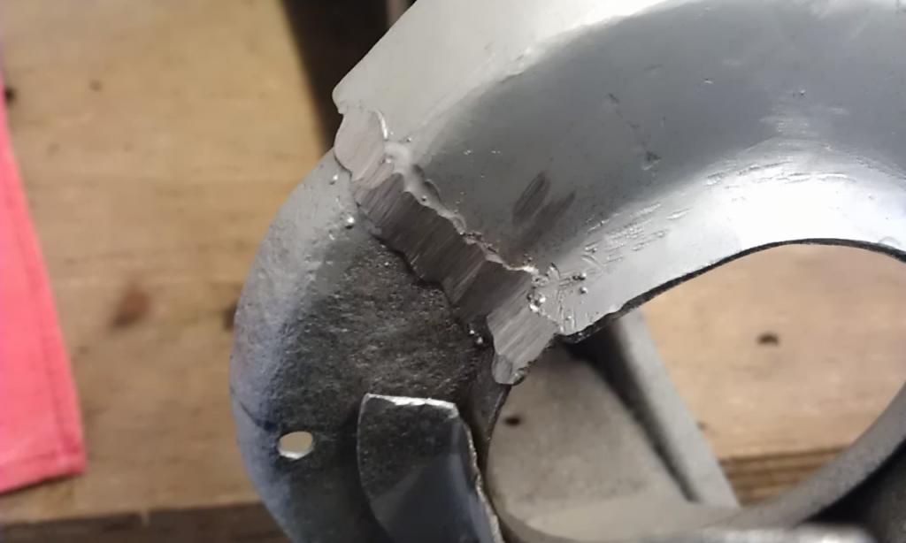 Here it is dressed down and primed: 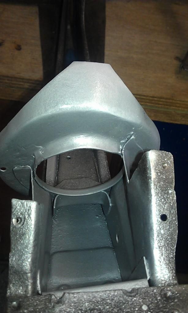 Cleaned all the internal area up as suggested and applied Hammerite KURUST. Here's a pic showing it starting to come together: 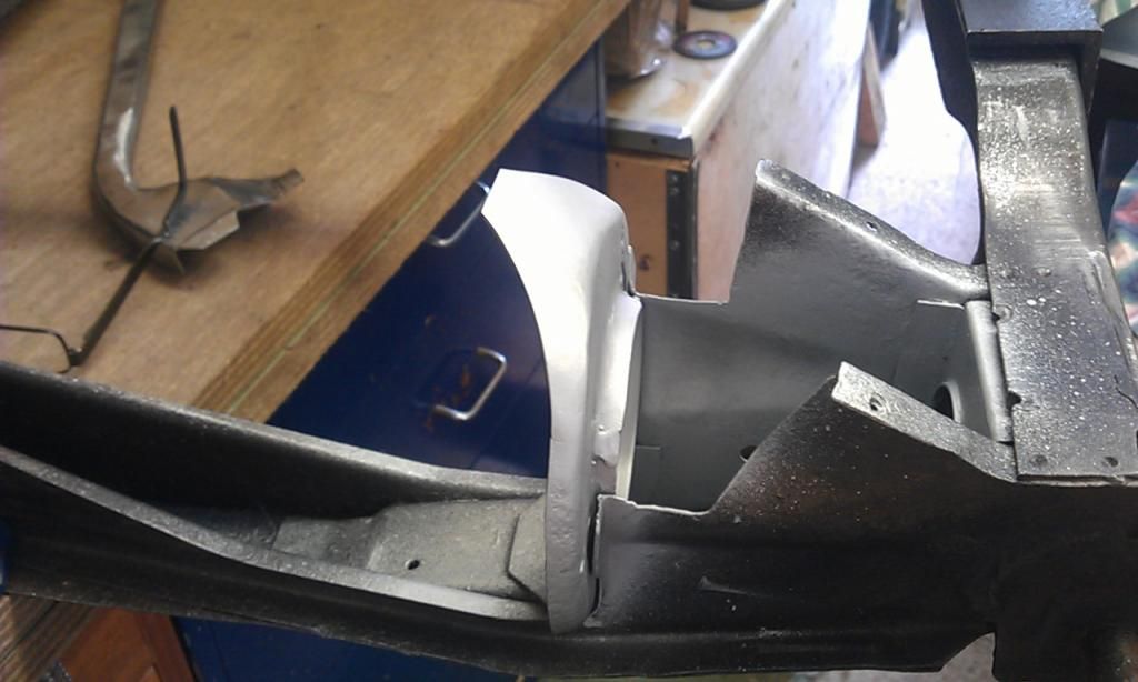 And heres the first main spar getting welding in place: 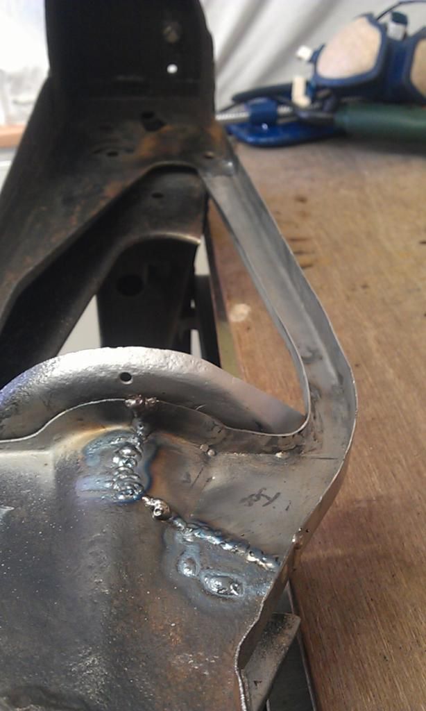 And then I ran out of gas - pick up a refill tomorrow :-) |
| |
|
|
Wild
Part of things
 Mini Restoration
Posts: 12 
|
|
Apr 10, 2014 20:14:35 GMT
|
|
Looking good Jonnyalpha! Keep up the good work man :-)
|
| |
“On a given day, a given circumstance, you think you have a limit. And you then go for this limit and you touch this limit, and you think, 'Okay, this is the limit'. And so you touch this limit, something happens and you suddenly can go a little bit further. With your mind power, your determination, your instinct, and the experience as well, you can fly very high.”
- Ayrton Senna
|
|
|
|
|
Apr 21, 2014 21:18:00 GMT
|
Looking good Jonnyalpha! Keep up the good work man :-) Thanks Wild :-) |
| |
|
|
|
|
|
Apr 22, 2014 13:12:39 GMT
|
Thanks Tony, if it wasn't for your posts on here I never would have started :-) I have now welded on the second main spar and dressed down the welds where required, only one piece left to make and then the R/H side will be completed. Also made a couple of repair pieces for my Mini bodywork and using what I have learnt doing the subframe I managed to knock up a rear quarter repair and weld it in place in a couple of hours - smokin!! Would love to see some pictures of the mini repair mate if you have any :-) Here goes: Heres the area to be repaired, it's the lower part or the 'Rear Quarter': 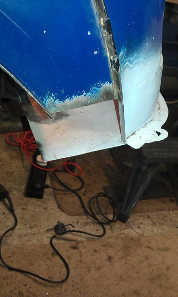 As I had cut the old damaged area out a long while ago I had to fid a pic on the web of what the finished article should look like, a quick search on google pulled this up - perfect. Started with a template made from an old cereal packet (made a mistake when cutting it, I missed of the folded edge on the RH side but spotted it before I cut the metal): 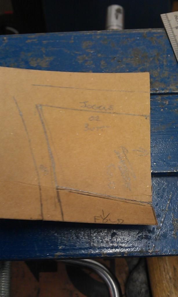 Next cleaned up some spare sheet steel: 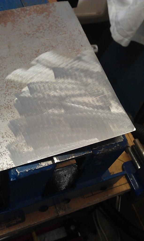 Folded the repair piece: 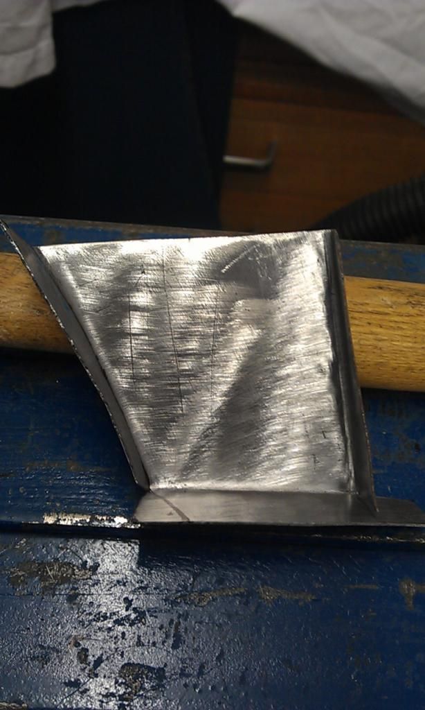 Sorry no step by step pics, I started with the curved fold (the wheel arch profile) and then the bottom and RH folded edge. To get the wheel arch profile I simply folded a piec of card over the existing wheel arch and marked the curve and then transferred this curve to the correct part of the template. Next I joddled the edge using my latest Home Made edge setter (don't get exited but it works). 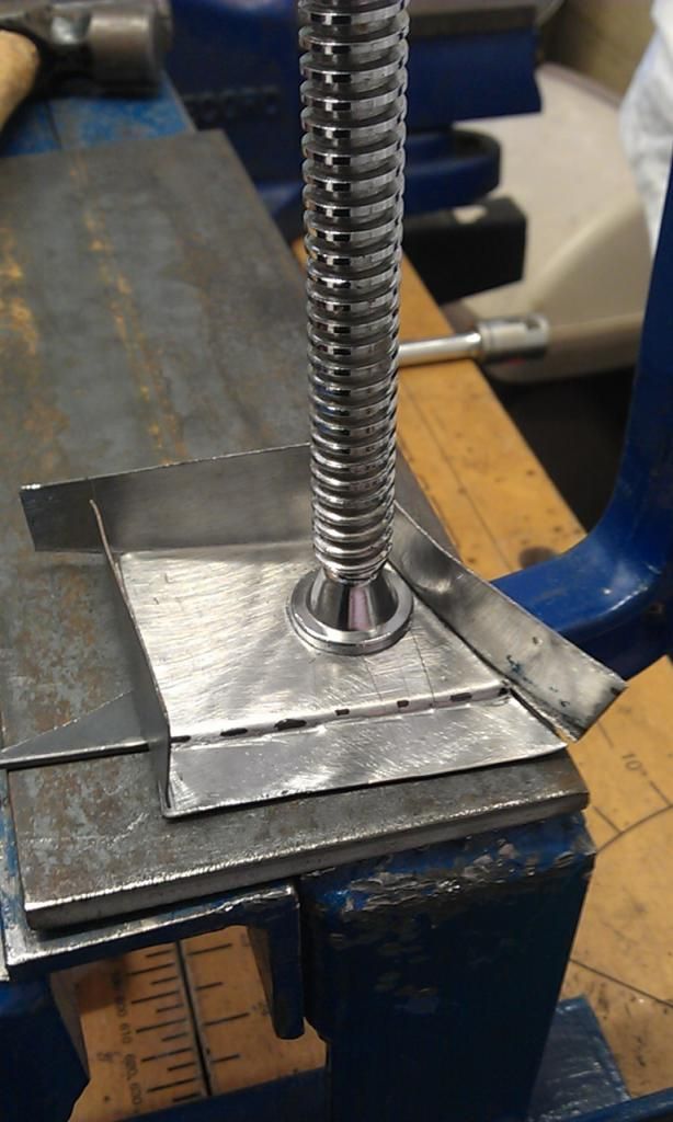 Thats a piece of 4mm plate to create a flat surface and a piece of 2mm to create an edge, seems to work fine for 1mm repair pieces, which is about right for Mini bodywork. Clamped the piece in place and made some adjustments: 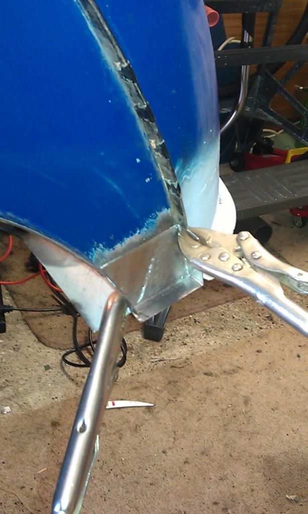 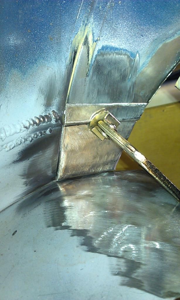 Then hit it with the welder: 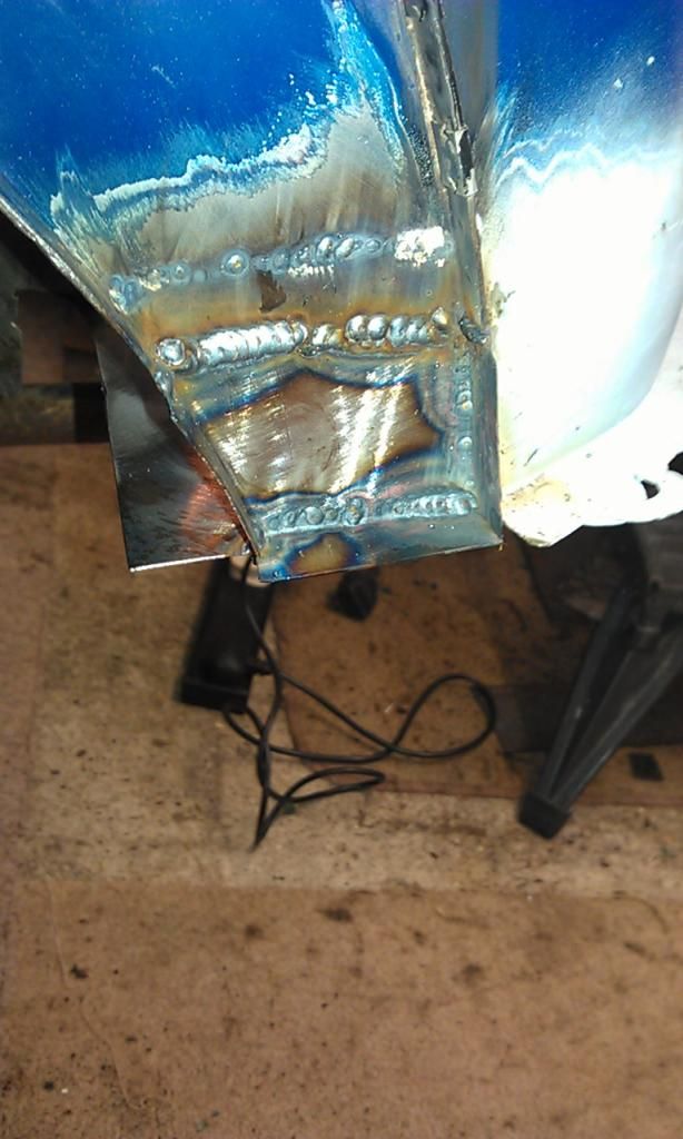 I rushed a bit with this and did not plan the welding, the top and right and side is OK but I should have been a bit more careful with the bottom edge, what you can see is the penetration, which is good however it will now be a B*** to clean up so I may have to use filler :-( I'll need to filler the top weld anyway so no real dramas. Just need to dress down the edges and paint.........Job done :-) |
| |
|
|
|
|
|
|
|
Small update on the Subframe rebuild, been slow going as I switched back to the Mini for a while. Just finished the last main strut. Small patch on the one strut that did not need replacing: 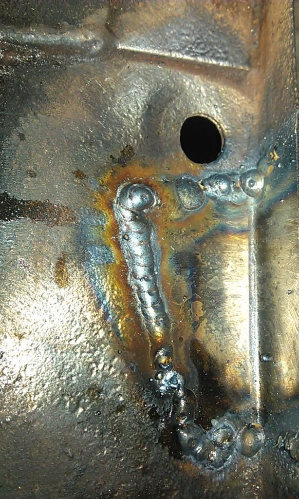 This was Butt welded all the way around, I'm getting a lot more confident with my welding and my welder, for 1mm metal I have sorted out the settings but often pre heat the area with a gas blow torch. The neat run above shows the results of Pulse Welding after being pre heated - sweet :-) And here it is dressed down: 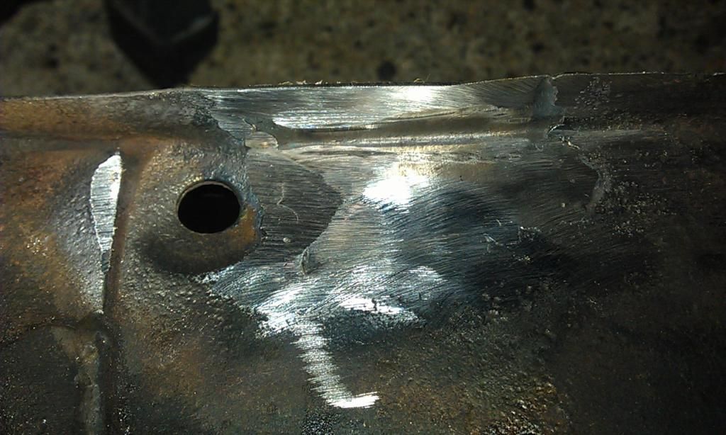 Here's the second main spar part welded: 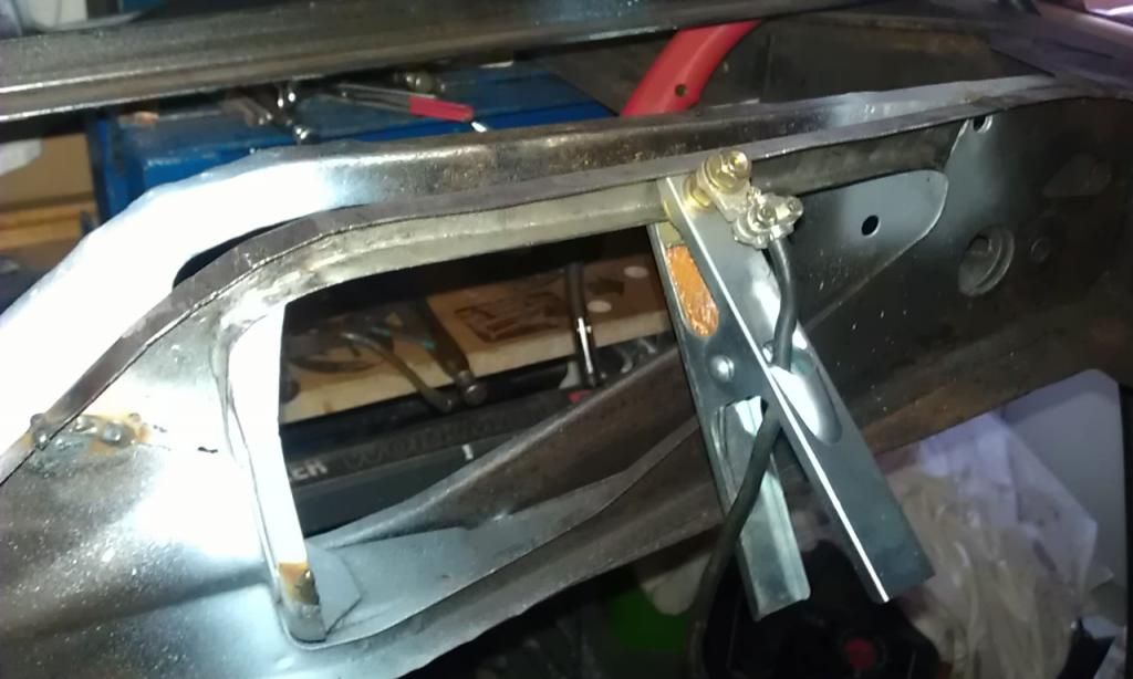 Whilst I was cleaning up the area, I noticed that then Rear Cone support seemed to have loosened somewhat, then with a little tug it came off: 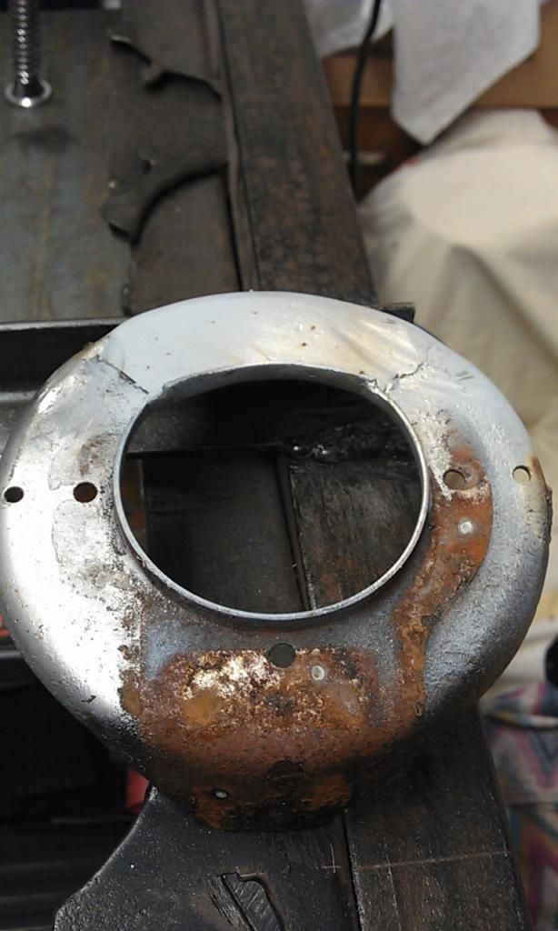 You can see three very small spot welds that were holding it in, one underneath and two on the RH side. I'll drill some holes and Plug Weld it back in place but now its off I can clean it up properly and spray it. Here's the RH side nearing completion: 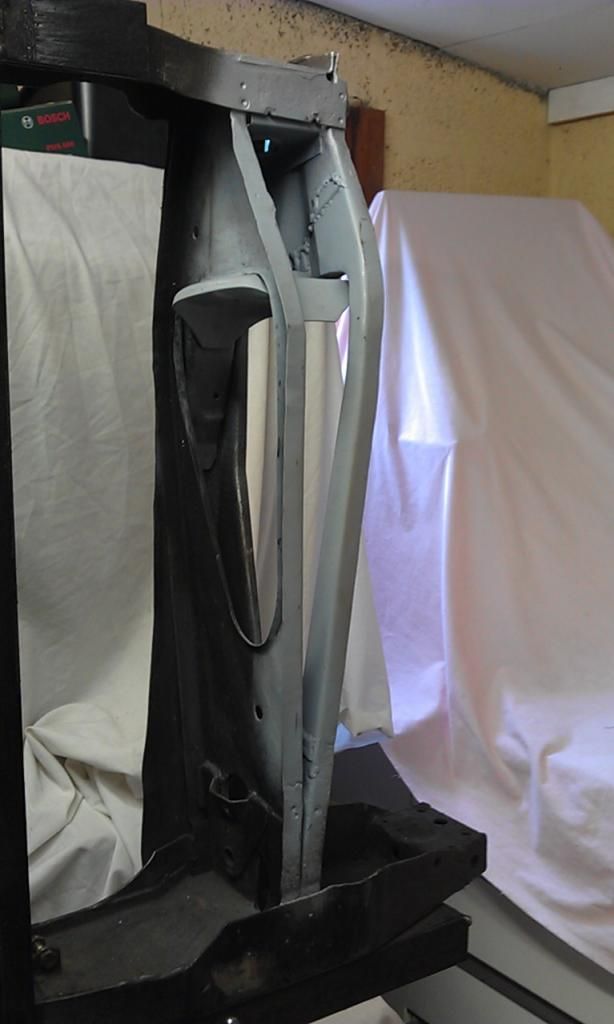 And here is the LH side: 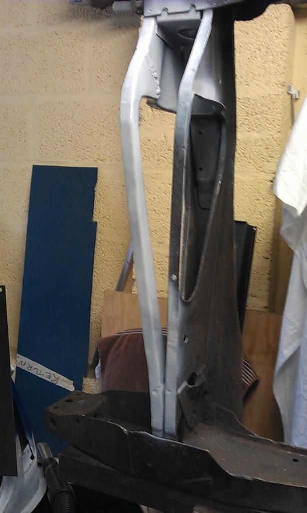 All I need to do know is make a couple of small brackets that I have already templated and make the second skid plate and weld it all up, Job Done, thanks to all the advice to make this possible :-) |
| |
|
|
|
|
|
|
|
OK here's the last bracket to be made on my Subframe: 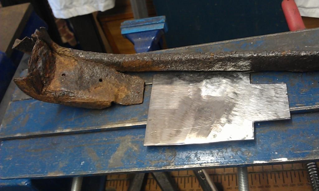 As you can see I already made a template and cut out the metal (1.5mm for this one). Here's what a good one should look like: 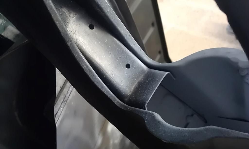 Its got a complex fold so I cheated by making a cut: 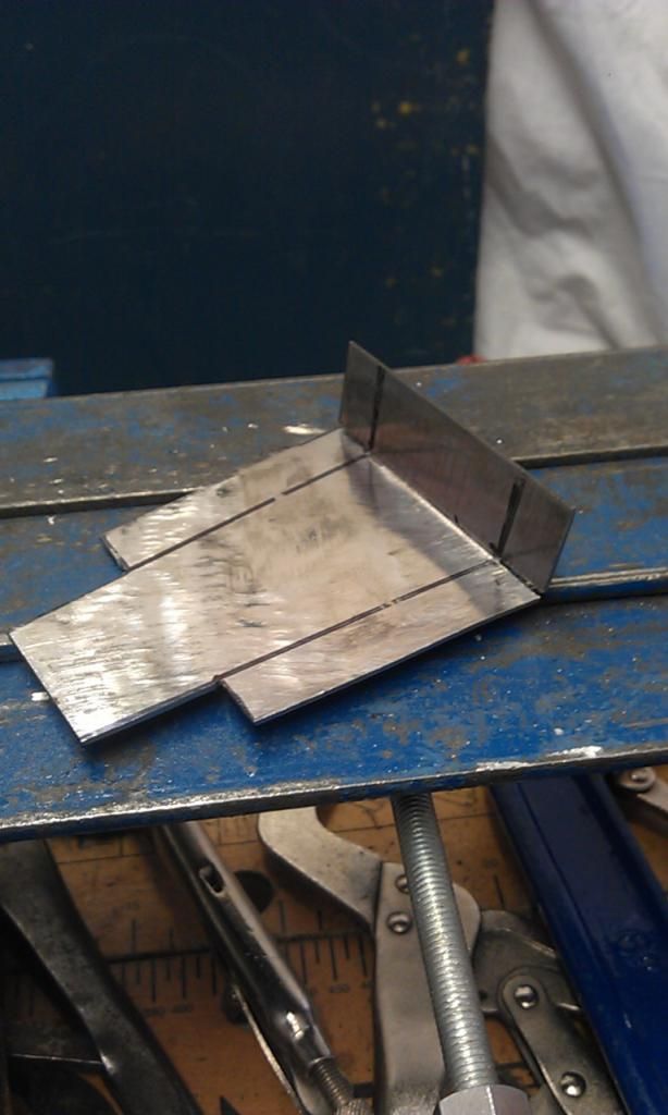 Here's all the folds done: 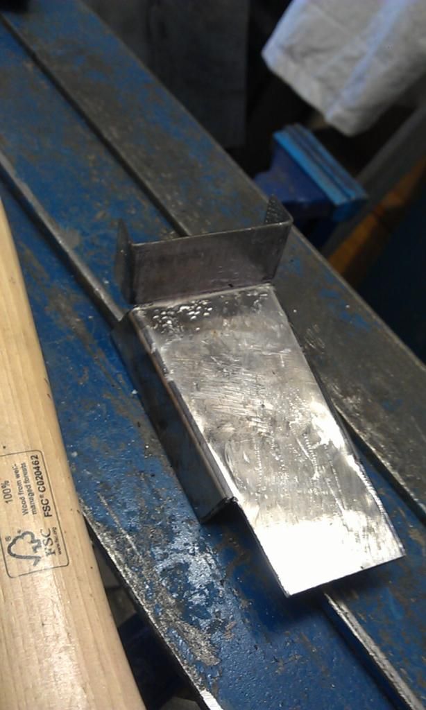 After a bit of adjusting here it is in place: 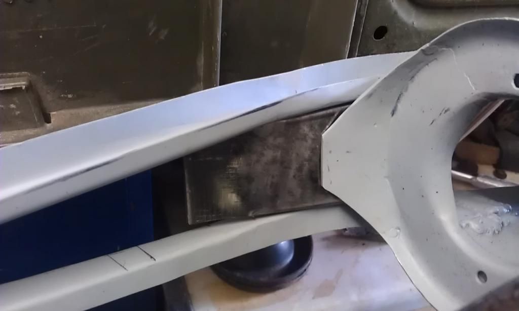 I then welded in the corner pieces: 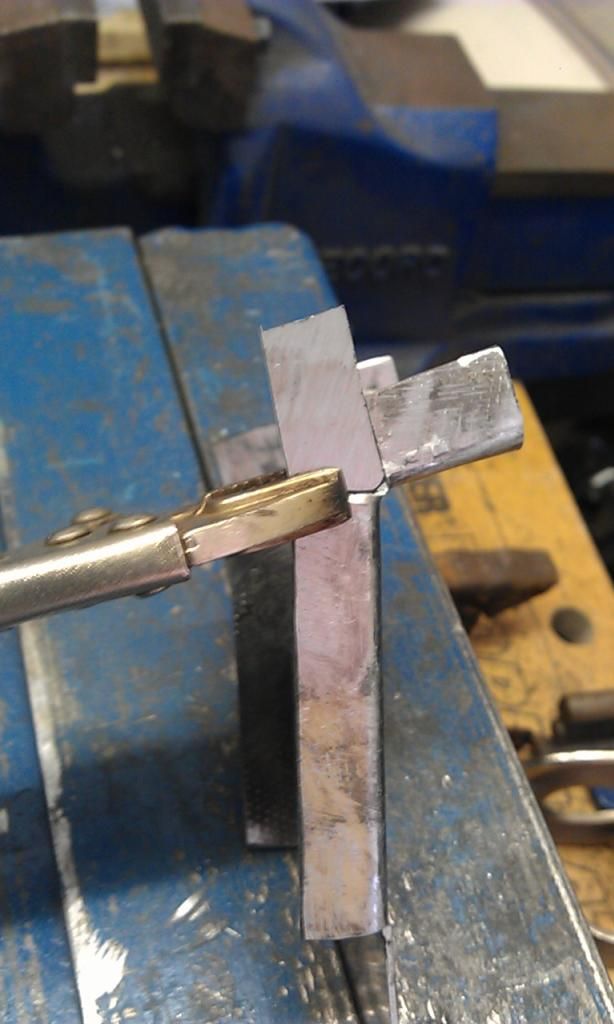 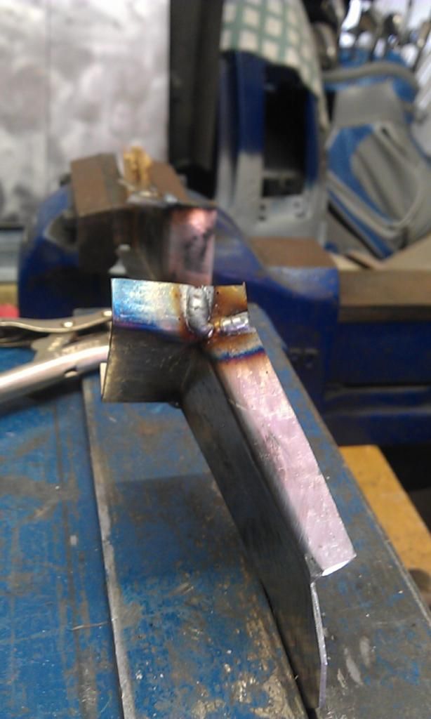 And here are the finished pair: 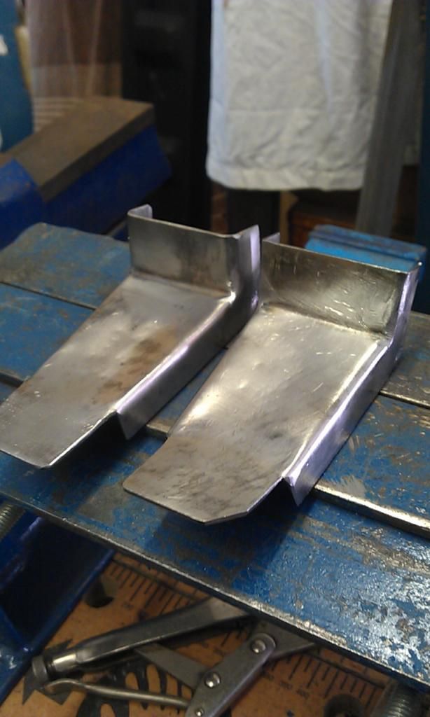 Just got weld them all up and make the last bottom skid plate. |
| |
|
|
|
|
|
|
|
Update on the Subframe Rebuild. Here is the Subby with both Main Spars, Support Plates and Brackets made and welded in: 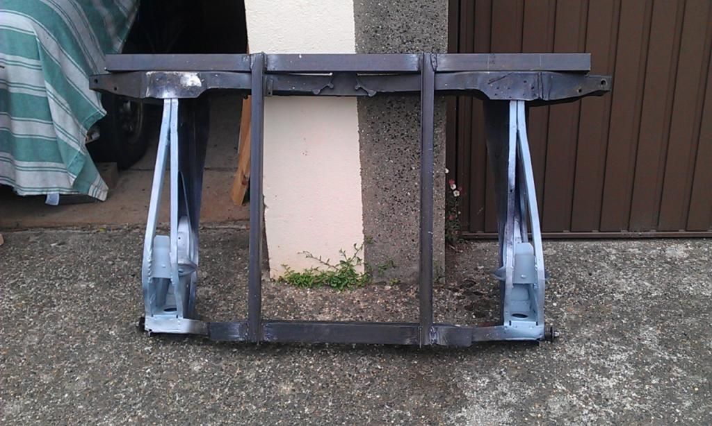 And here it is with both bottom plates finished and test fitted: 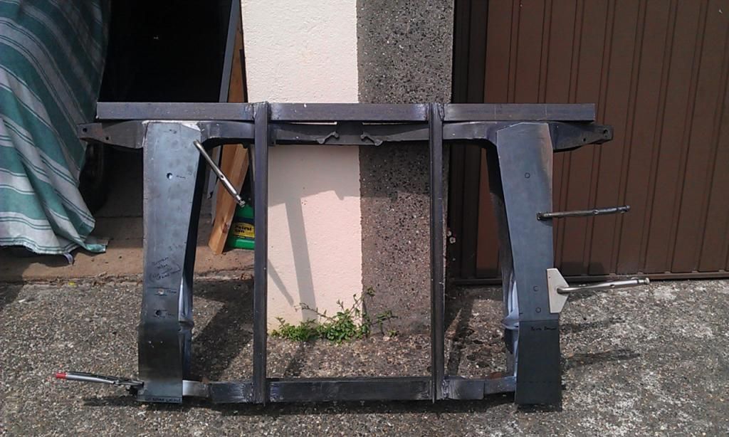 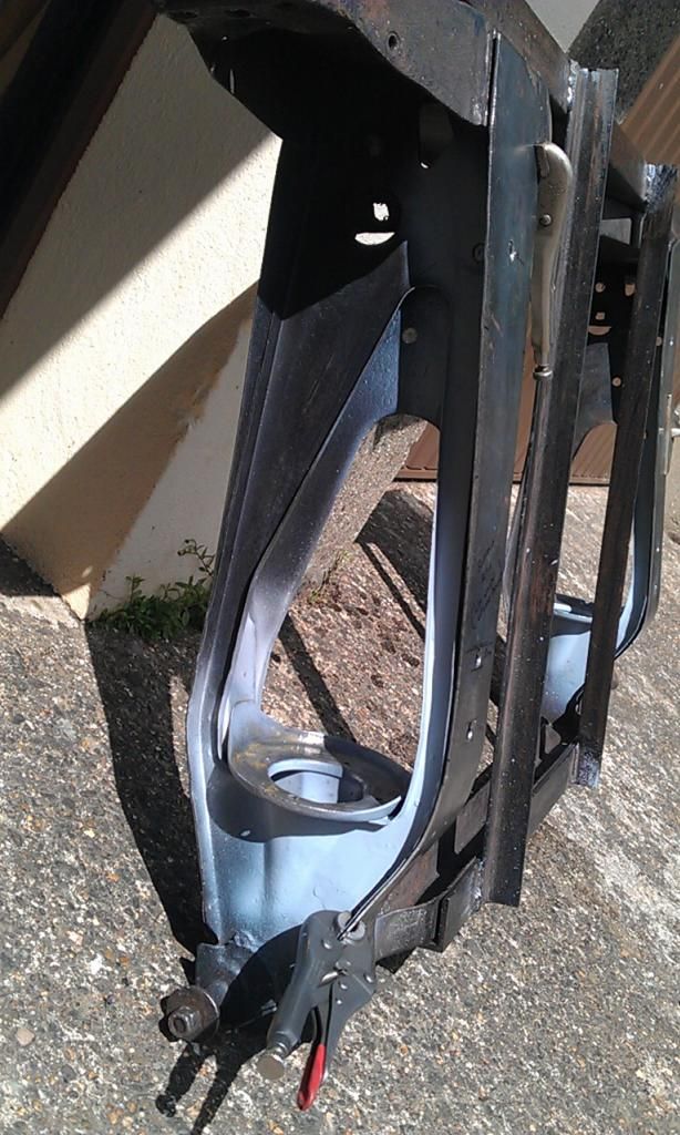 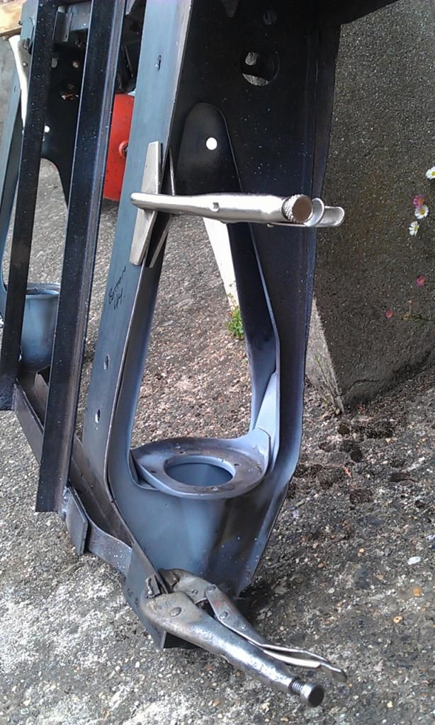 Still a bit rusty on top so time for a Twisted Knot, small repair to make to the end of the Left Plate and a tiny repair needed on the Right Plate: 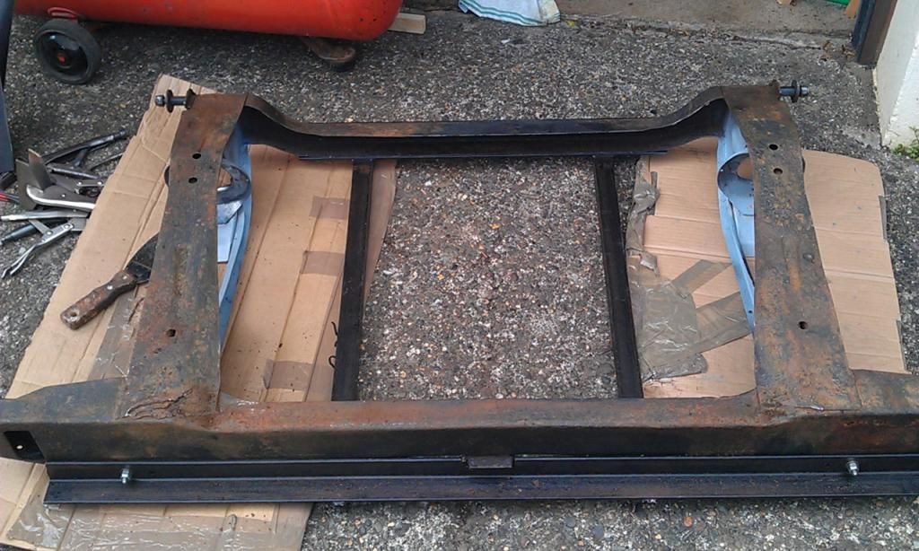 Spent a hour or so cleaning and scraping and then applied some KRUST to any rusted areas: 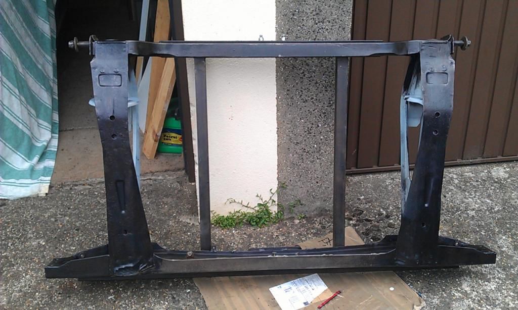 A little more scraping required, a lot of holes to be drilled in the skid plates so that they can be plug welded in place, weld on the Rear Cone Support Cups, seam weld anywhere required, sand down again, prime with Epoxy Primer and Top Coat TBC? |
| |
|
|
|
|
|
Jun 10, 2014 19:39:34 GMT
|
Subframe rebuild update: Spent the day in the workshop fabricating the indents in the bottom plates and drilling the plug weld holes: 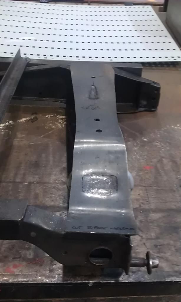 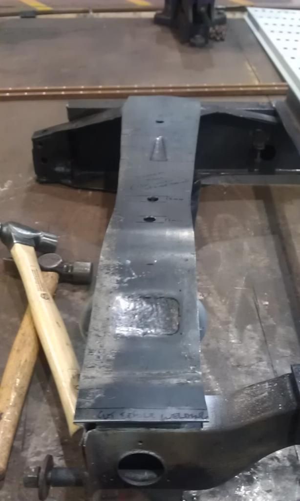 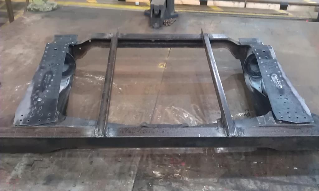 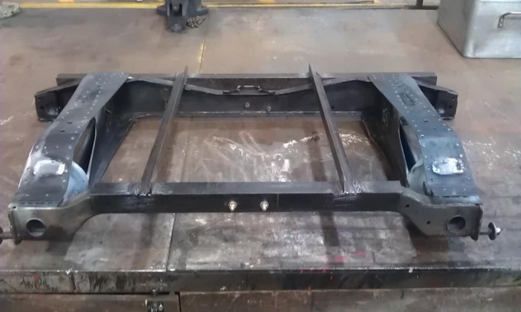 The indents need tidying up but I can do that at home, just wanted to get the bulk done and the holes drilled using the Anvil etc and Pillar Drill as I only have a Hand Power Drill at home. Clean, Prime and Paint next :-) |
| |
Last Edit: Jun 10, 2014 20:15:48 GMT by jonnyalpha
|
|
|
|
|
Jul 20, 2014 10:11:28 GMT
|
Guys; Possibly the last post in this instalment, just an update on my Subframe Rebuild which was is within this thread to show the finished product (well finished from a fabrication point of view). Here's a link to part of my Mini rebuild thread which covers the last stages of the Subby. And here is the finished product with a couple of coats of Epoxy Primer: 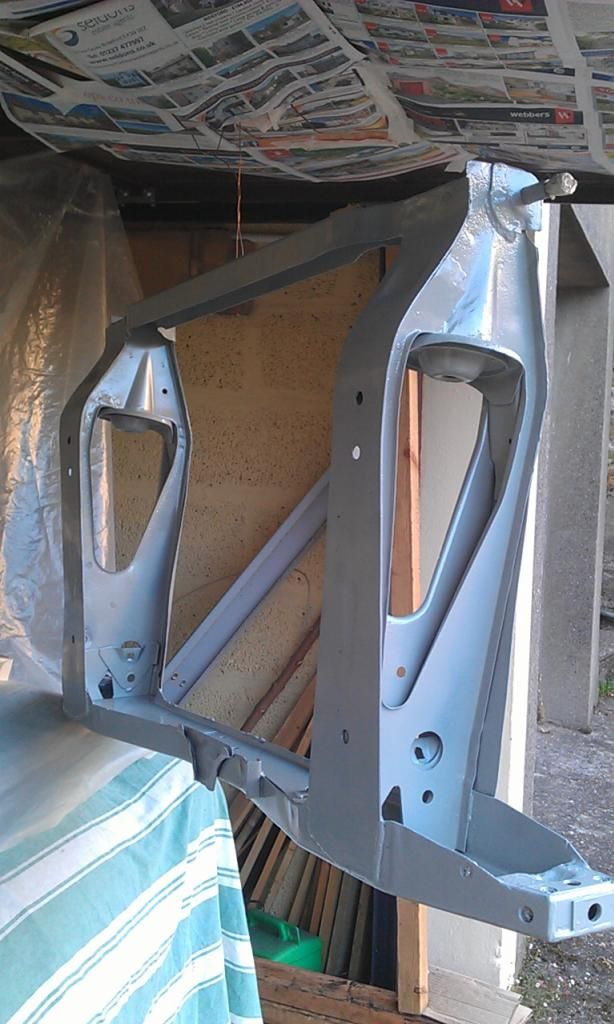 Thanks for all the advice and tips, without which I would not have achieved this milestone :-) |
| |
|
|
|
|


