|
|
|
May 19, 2010 18:42:34 GMT
|
|
Dave
the Short answer would be yes, fitting a 16swg u shaped channel would stiffen the floor sufficiently to jack it, but if Mazda did not think it necessary at the time of manufacture, then I'm not sure I would personally go down that route
Tony
|
| |
|
|
|
|
wallopadonkey
Part of things
  stunning grinder! curse word welder!
Posts: 234
|
|
May 20, 2010 22:11:11 GMT
|
|
yeah i see what you mean everything on the car is done for lightness all inside the sill are swaged holes etc.
however i am now more interested in being able to jack it safely after i have repaired all the damage so as not to undo the repairs if you see what i mean,
most cars have good strong jack ponts but i don't get it on this at all!
dave
|
| |
1983 mini city e
1985 miny Mayfair
1997 Audi a4 tdi
2003 gsxf 750
|
|
|
|
|
|
|
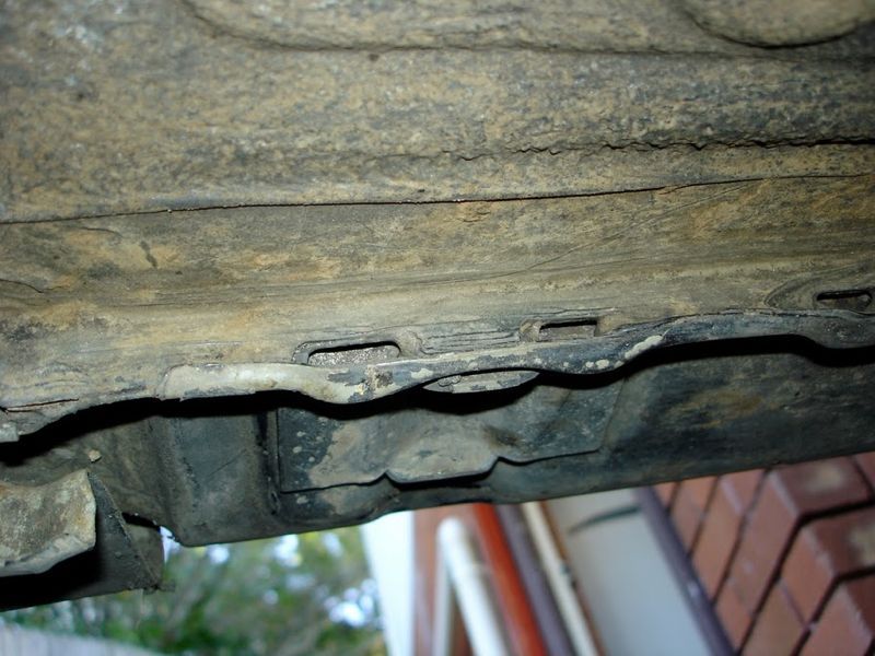
1995 RHD BMW E34 530i MTech V8 manual. Hi Tony Excellent article and a real inspiration. I am in the process of repairing the outer sills and jacking points on the drivers side and have cut out the worst rot to assess the job in hand. As you can see the bottom lip below the jacking point had lost most of its layers and I need to know what the other layers look like to be able to work out a plan of action and fabricate a new outer sill. The remaining layer has three slots in the bottom edge - are these drainage holes for the sunroof pipe? A bit boggled about where and how to start, what to cut out and what to leave. Will post more pictures when I work out how to attach more than one. Andy Attachments:
|
| |
Last Edit: Jun 7, 2010 19:01:17 GMT by MacBeagle
|
|
|
|
|
|
|
|
Andy
I definitely need to see more pictures, also photograph the other side if you can, to show what it should look like when it is finished
Tony
|
| |
|
|
|
|
|
|
|
Tony Thanks for the reply. The passenger side is exactly the same, hence no reference and I can't seem to find the relevant pages on RealOEM that show the sill panels. Can you explain how to upload more than one file? Cheers Andy Attachments:
|
| |
|
|
|
|
|
|
|
|
Andy
You need to upload your photos to Photobucket or similar, and the paste the image codes into the message
I am sure that there will be somewhere on the forum that tells you all about it
Tony
|
| |
|
|
|
|
|
|
|
|
|
| |
Last Edit: Jun 8, 2010 20:48:46 GMT by MacBeagle
|
|
|
|
|
|
|
Andy Try like this This is a picture of the general condition of the sill edge  Front Drivers side jacking point before cutting began  Close up of jacking point  Front wing area with attachment bolts removed  I am pretty clear about how to progress with making a new jacking point but its where to start building up the bottom edge and where to fabricate new drainage channels. |
| |
|
|
|
|
|
|
|
Andy I have not worked on an E34 before, but looking at the pictures the 3 slots are not drain holes, I suspect that they are more likely to be location holes for the jack or something like that, the reason I say that is because they are outside of the sill I suspect that the sunroof drain tube was supposed to drain down the centre tube that the jack also locates on on the sill The construction idea looks similar to a six series that I have done Here you can see the inner stiffener that sits inside the sill, this has a hole in the centre that the jacking support tube goes through 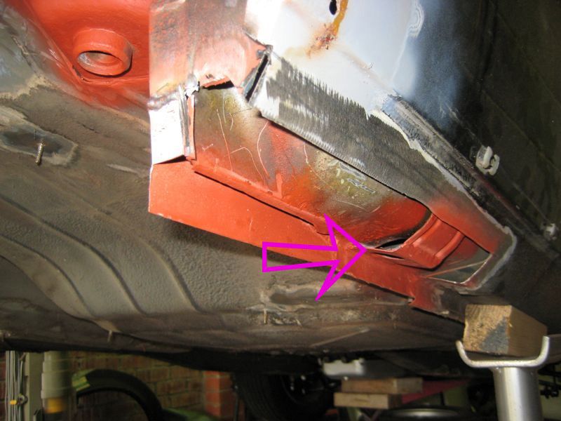 Then the outer sill patch has a corresponding hole in it 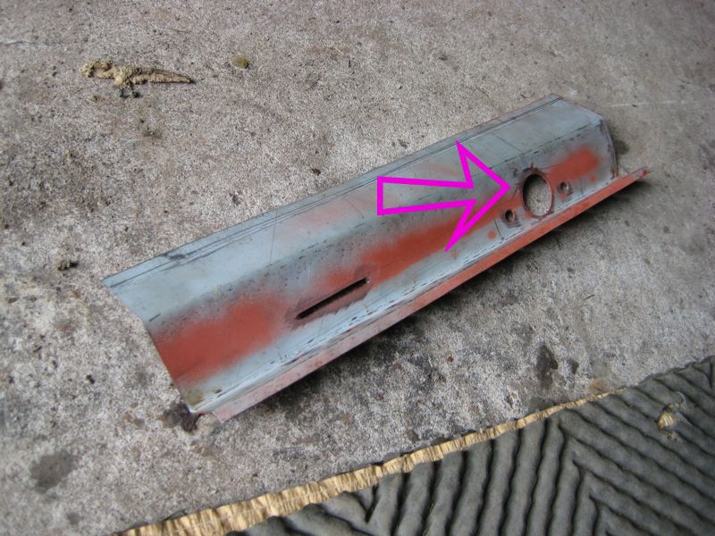 The the jack support tube is pushed up through the aligned holes and then pool weld all the 3 thicknesses together 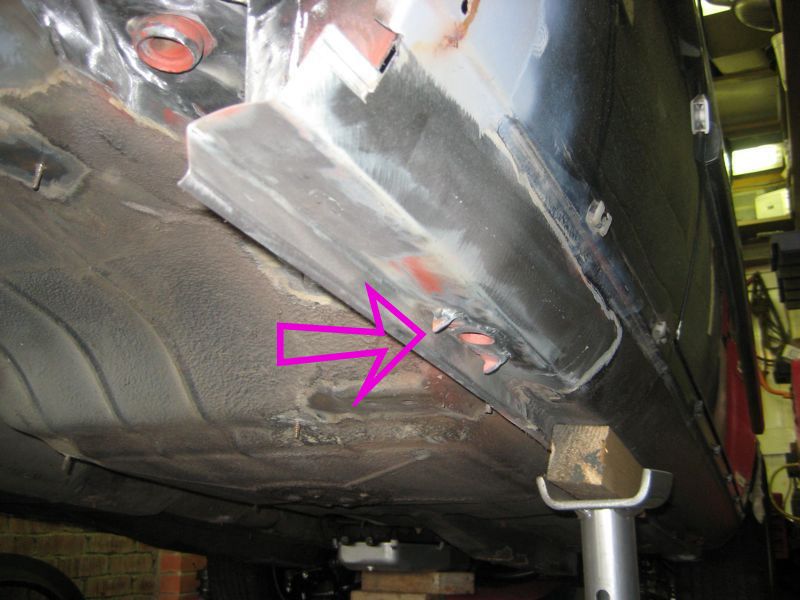 ] Hope that helps If its not clear let me know and I will try to sketch something down Tony |
| |
Last Edit: Jun 8, 2010 21:26:57 GMT by tonybmw
|
|
|
|
|
|
|
|
Tony
That really is a great help, thanks for taking the time to explain. Will get down to making some templates before I cut any more metal away. Will keep you posted.
Andy
|
| |
Last Edit: Jun 9, 2010 10:01:06 GMT by MacBeagle
|
|
|
|
|
|
|
Jun 10, 2010 21:09:02 GMT
|
|
|
| |
|
|
vanny
Part of things
 
Posts: 10 
|
|
Jun 15, 2010 22:19:03 GMT
|
This thread is the greatest thread EVER!!! If only because it gave me the encouragement I needed to replace the towing eye on the BX. The BX is an ongoing project/swapathon that I suspect would make people here proud, check it out on the BXProject; As requested, here is my experience of using this thread to create something fantastic! First up the remains of the towing eye, and what I need to duplicate (apologies for the pic being on the curse word);  It's not meant to have that sodding great big hole in the spreader! This is the only part unique to the BX 16valve, from what I can tell it was welded onto the car in a rush shortly before lunch break in the factory in Rene's. Its a pretty heavy bit of metal not quite 2mm thick!  This is the 'new metal' cut to size. It's 2mm plate. This is the bit that the thread really helped with, understanding the radiusing in corners etc. I can't show it pre cut because I marked up in pencil (ran out of chalk) so the pictures didn't come out. Its cut out with a 1mm cutting disc.  I'm reusing the 10mm bar that makes up the towing 'loop' mostly because i'm tight. So cutting it off with the cutting disc and a carefully shaped flat cold chisel (as suggested by this thread). sandy flappy disc put to good use;  And the three pieces. Using the hints and tips here I realised I could bent this up in my vice quite easily if I gave the folding order some thought. I also gently adjusted/fettled the new steel into shape;  And finally the (almost) finished article. Its part welded, part tacked. When I bought the car the loop was out of alignment and regular brake downs haven't helped so I will weld it up fully once I can get the bumper on and make sure of the alignment.  Ah, done. All in, it probably took less than an hour, mostly because i've got a small garage so everything is to hand! My tips would be the following. 1) Tape measures SUCK! If i'd had a steel rule, a set of calipers and square I'd have saved a LOT of time. 2) Pencil is grey, steel is grey (unless you have fancy Zintec), this is NOT a helpful combination. I have 144 sticks of chalk in the post for the next project (and rest of my life no doubt!). 3) Don't be afraid of cocking it up if your working on a 'new' part on the bench, you can always weigh it in and start again. 4) Metal sheet on your workbench, hook it to the 'earth' of the welder and now you don't need to do the earth lead shuffle/balancing act when your welding! Thanks for your help Tony |
| |
Last Edit: Jun 15, 2010 22:27:51 GMT by vanny
|
|
wallopadonkey
Part of things
  stunning grinder! curse word welder!
Posts: 234
|
|
Jun 16, 2010 20:10:12 GMT
|
|
tony bmw for 'MBE'!
|
| |
1983 mini city e
1985 miny Mayfair
1997 Audi a4 tdi
2003 gsxf 750
|
|
|
|
|
Jun 16, 2010 22:13:07 GMT
|
|
Vanny - Great job and some good tips, A steel rule is definitely better for accuracy, and you could also use a scriber for marking out.
Wallopadonkey - Not sure about that but thanks for the vote of confidence
|
| |
|
|
Em
Part of things
  Fuel Injected? Carb Infested!
Posts: 601 
|
|
Jun 17, 2010 14:12:40 GMT
|
|
Hey Tony,
Just wanted to say thank you for taking the time to put this fantastic thread together. It’s inspirational stuff and has encouraged me to tackle work I’d previously thought needed a box folder, a bending roller, a spot welder, a plasma cutter, a shrinker, stretcher, swager, notcher, nibler and an English Wheel at the very least!
Cheers again!
*Heads off to garage to try and make a battery tray…*
|
| |
|
|
wallopadonkey
Part of things
  stunning grinder! curse word welder!
Posts: 234
|
|
Jun 22, 2010 21:47:15 GMT
|
|
how about an OBE?
|
| |
1983 mini city e
1985 miny Mayfair
1997 Audi a4 tdi
2003 gsxf 750
|
|
|
|
|
Jul 10, 2010 18:48:48 GMT
|
Hi Tony Continuing with the E34 sill renovation but interrupted by building a welding table and your excellent sheet bender - how did I manage before? As you can see in the pic, doing a piece that requires the stretching technique and I need to tighten the bend at the arrow. Do I keep fettling it with the cross pein - the metal is getting very thin and I need to put a spot weld at that point. In theory would the bend go to a right angle if you kept bashing? BTW the metal is 1.2mm/18g.  |
| |
|
|
|
|
|
Jul 11, 2010 21:32:14 GMT
|
Andy You could not stretch it enough to make it a 90 degree bend, but you will be able to stretch it enough to form a curve that covers 90 degrees There are 3 pointers I could give that should help Hope this helps Tony |
| |
|
|
|
|
|
Jul 11, 2010 21:59:16 GMT
|
|
Hi Tony
Yes, it helps a lot. I did think I might be a bit ambitious given the width of the fold I need to beat and the width of the metal bending to that process. The fold has to be that width/depth because that is the vertical edge of the sill. Would it be better in this particular case to make it out of two pieces and weld them together I.e. curve the inner sill piece with a smaller fold as you suggest and then lap weld it to the vertical sill edge?
|
| |
Last Edit: Jul 11, 2010 22:01:07 GMT by MacBeagle
|
|
hairymel
Club Retro Rides Member
avatar by volksangyl
Posts: 1,081
Club RR Member Number: 207
|
Making panels.......hairymel
@hairymel
Club Retro Rides Member 207
|
|
|
|
i think tony is saying to make the bend tighter rather than making your flange narrower.
ie make the point/corner of your L a sharp right angle rather than a rounded bend
hth
mel
|
| |
whats that burning smell?
oh curse word :-(
|
|
|
|


 ]
]