B-8-D
Posted a lot
 down to one car!!
Posts: 4,038
|
|
Mar 31, 2009 18:30:37 GMT
|
|
i like the idea of using sheet metal instead of more tubes works too..
"is there anyway of replacing the 4 tubes with only 2....
yes straight from stut top mounts down to the junction where the lower rear wishbones mount..
the sheet metal can prob be used at the rear too maybe incorperated into bulkhead as a stressed member?
always remember things like steel tube is so much stronger if used in tension rather than compression and bending forces should be avoided if possible unless u are wanting flex..
some decent spaceframes are designed with almost all tubes used in a tension..
look at beardmores chassis to see a decent designed spaceframe/tube frame...
imo he builds some of the best chassis about, design-wise.. a lot of very well respected and proffesional chassis builders build stuff nowhere near as good as most of his designs..!
but obviously there is always anoying things like space for the driver/petroltank/engine/gearbox etc to think about and to design around...
can any of the engine or box be used as a stessed member??
maybe the sump can be incorperated into the lower spaceframe as a fabricated whole? and used to mount the engine also perhaps...?
just some ideas for u to chew over...
si
|
| |
|
|
|
|
kee
Posted a lot
Posts: 4,991
|
|
Mar 31, 2009 18:57:33 GMT
|
Si, i cans ee where you are coming from but for this report that is probably going to far, i've got to a point where i have plenty to write about, good and bad points on this frame and suspension and how it could be improved. i have since changed the frame again, the frame is now box section where the suspension arms mount as this makes the mounting of them very easy, i also now need to do one last part and that is somewhere to mount the engine. then is time to get writing. thanks for the offer Phil, i'll see where i get to and will give you a shout if needed  |
| |
|
|
Siert
Posted a lot
Posts: 1,105
|
|
Mar 31, 2009 19:54:22 GMT
|
|
Looks like your doing a good job.
A quick browse trough this thread tells me somebody has already mentioned Allan Staniforth's race and rally source book here. Don't know if it has been mentioned here but I just read his book "Competition car suspension" which is very well written and very recommendable.
|
| |
|
|
kee
Posted a lot
Posts: 4,991
|
|
Mar 31, 2009 20:01:53 GMT
|
got em both  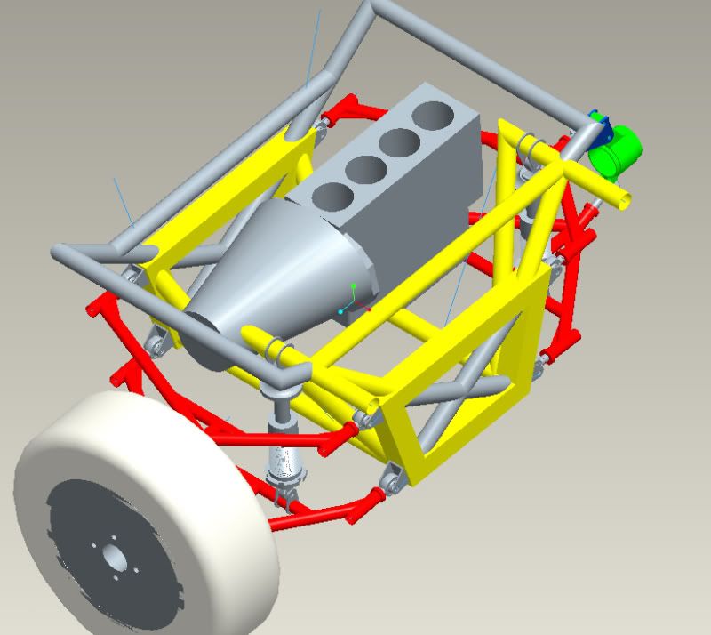  new piccies show the box section and better wishbone mounts. changed the shock mounts and it looks like i had the same idea as black8driver. added a big brace from front to back which will hold the upper engine and gearbox mounts, not sure if i need to design these though. |
| |
|
|
|
|
|
|
|
I'm a bit late to help with your college project, but for your full space frame idea maybe you should consider suspension similar to a civic? Think about it, with the upper arm mounted above the wheel it will give loads of space for the shocks and the forces will feed into a much lager box reducing the amount of metal needed.  also this Suspension calculator is really useful. |
| |
Last Edit: Apr 1, 2009 10:26:21 GMT by TerraRoot
|
|
kee
Posted a lot
Posts: 4,991
|
|
|
|
i saw that a while back and to me it looks like it can't take the forces aswell as a conventional double wishbone setup. for my full spaceframe the engine will be sat further back and will be pointing in a different direction so won't have to worry about it |
| |
|
|
John
Part of things
Posts: 347
|
|
|
|
|
Looking a lot better.
A few comments......
People have talked about it looking too heavy because of the amount of tubes. Just use thinner tubes. A triangulated structure in thin tubes is much better than a poorly triangulated structure in heavy tube except it is more work to construct. So aim for perfect triangulation and make the diagonals smaller. They could be actually steel hauser (cable)....
Your wishbones mounted along the wishbone will impart big bending loads into the wishbone and mean you have to run a high spring rate. Try to get them closer to the wheels even if you have to compromise something else.
The dragster chassis that was posted has different requirements to a car that will go around corners and lacks triangulation in the engine bay.
Have you built a wooden model of your designs? If not DO IT!!!! You will learn more in 30 mins playing with model than you have learnt on theis thread, trust me!
Get some 6mm square wood (B&Q sell it) and glue it together (a hotmelt glue gun works well). You can even make a scale model of your engine from cardboard. But the main thing you are after is the structure layout. It can be tweaked to fitaround the engine.
If you need to triangulate an engine bay and get above an engine then build a pyramid above the engine. Cant find a picture sorry.
keep at it.
John
|
| |
Last Edit: Apr 3, 2009 20:04:18 GMT by John
|
|
|
|
|
|
|
People have talked about it looking too heavy because of the amount of tubes. Just use thinner tubes. A triangulated structure in thin tubes is much better than a poorly triangulated structure in heavy tube except it is more work to construct. So aim for perfect triangulation and make the diagonals smaller. They could be actually steel hauser (cable).... Until it's a monocoque? Have you built a wooden model of your designs? If not DO IT!!!! You will learn more in 30 mins playing with model than you have learnt on theis thread, trust me! Get some 6mm square wood (B&Q sell it) and glue it together (a hotmelt glue gun works well). You can even make a scale model of your engine from cardboard. But the main thing you are after is the structure layout. What he said. I built several different models at 1:10 scale to get comparative results (monocoque, spaceframe, backbone, ladder just to see how curse word it is), 1:5 scale might be better once you know what you're doing. |
| |
|
|
kee
Posted a lot
Posts: 4,991
|
|
|
|
i thought about doing a scale after i read about yours John, but it's too late now and the project is more to do with the suspension than the frame anywho. i'll probably do one for the full spaceframe though |
| |
|
|
kee
Posted a lot
Posts: 4,991
|
|
|
|
oh, and i re-drew my wishbones at uni and did some FEA, with a 8KN force acting on it from where the wheel mounts it has a biggest displacement of 1.8mm, which can be sorted using a rib as when i put the ribbing in the model it wouldnt compute. the stress was around 128N/mm^2. i think i will increase the diameter and/or wall thickness and see what happens from that, here is the FEA results 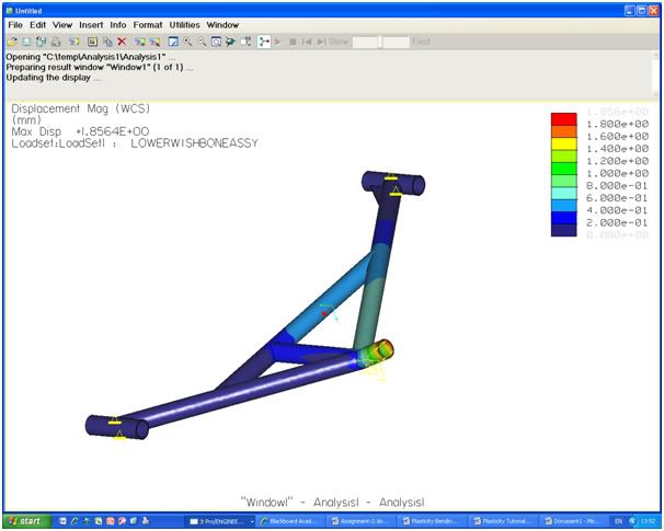 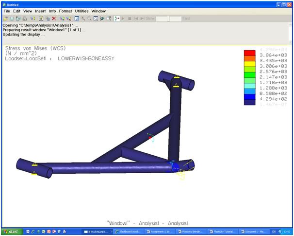 my model was missing some parts that are in the model above. the pro/e i have at home is not a student version so i cant open those files on the uni computers which have the student version. although phil (psmurfy) may have a way around it ;D also not including stresses from the coilover. |
| |
|
|
|
|