|
|
|
Apr 15, 2024 22:54:03 GMT
|
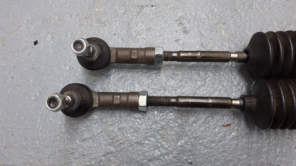
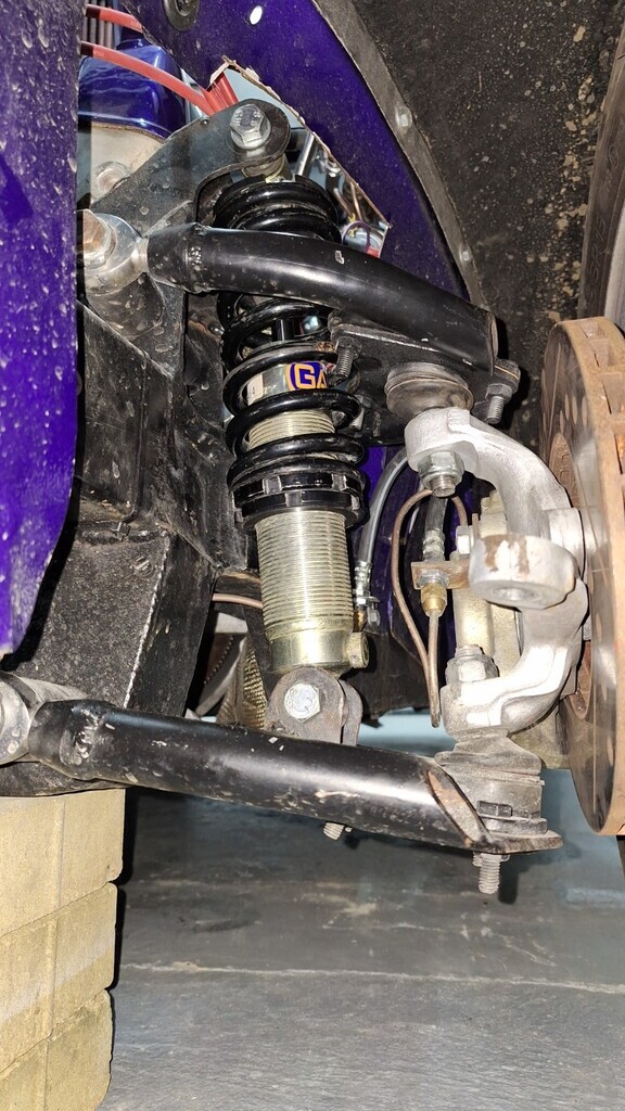
Just come in from a couple of hours on it - found a couple more horrors, but options are now becoming clearer. I broke the rack down to see where it had been narrowed, it seems to be done to the correct measurements, but it's just not quite straight. The daft thing on these racks though, is you can just cut the end off and have it turned down and a new thread cut and then just screw the cup back on & stake it. Far easier & safer. 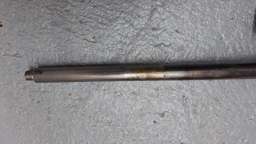 And the differently adjusted TRE's. I found out the reason for this odd adjustment later on. (and the bad butt welded joints - again they can be cut down and re-threaded). This is the maximum steering available on the passenger side, not much eh?
Thats because the brake caliper hits the lower wishbone. The odd TRE length was to stop this! The upper mount holes are not in alignment - obvious here; so they will need to be welded up and new holed drilled.
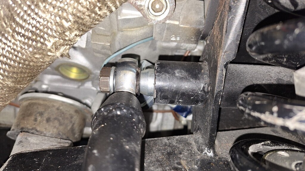
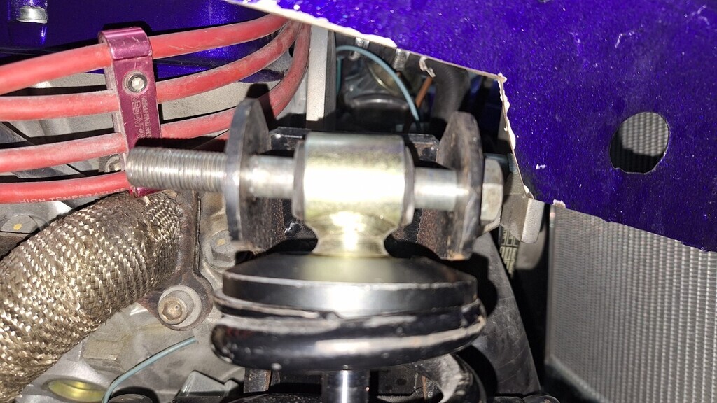
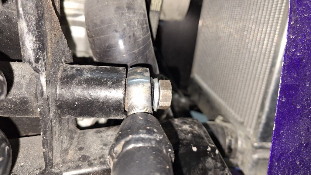
One bit I can't work out is why all 4 wishbones have been fitted with the rose joint spacers at the back but the rose joints are tight at the front? Why not fit thinner spacers both sides??? I will rectify this as I see no reason not to.
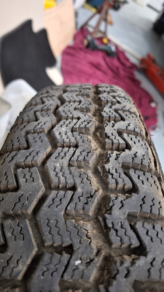
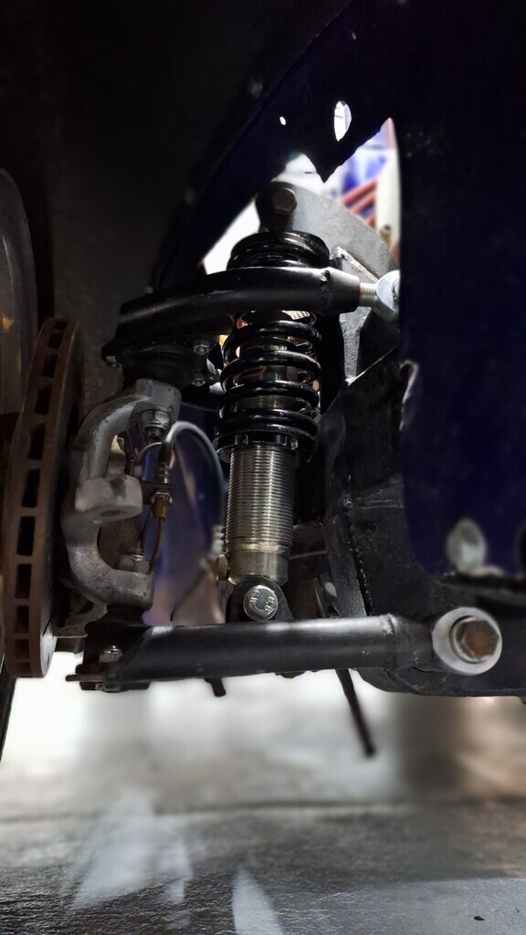
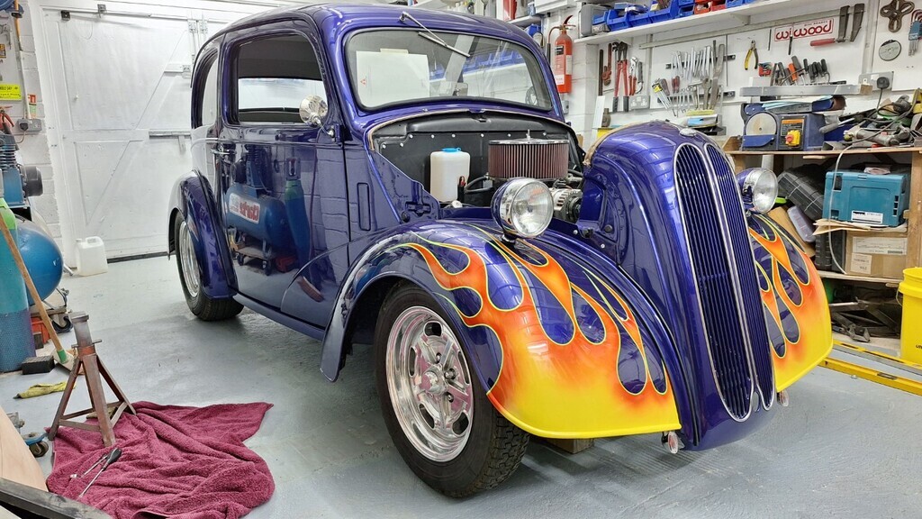
 Hmmmm....nice groove in the tyre - that will be where it was ripped into by the headlamp mount (which ripped the wiring off aparrently) before it was given back - how low was it before then if it's still too low now? Anyway, I reassembled it with the original springs and put it on a flat level section of the garage floor, just over 3" clearance under the grill and the suspension arms are at this angle;
And with it sitting on some bricks approx where I think it ought to be - 5" under the grill - I might get away with 4.5" as there is enough clearance everywhere else. A bit more angle than I would like, but I might be able to lose some of that when I alter the balljoint plates.
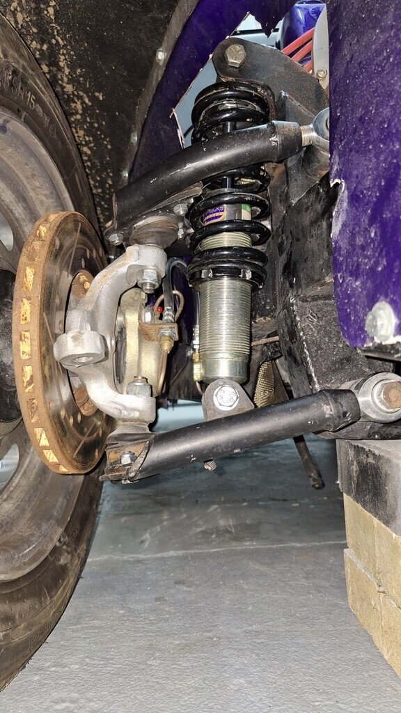
The springs are 425Lbs and are 8" open, with the weight of the car on them they compress to 6 1/8" - I'm sure there's a formula to work out what the poundage should be as I believe they should compress less? I forgot to measure the length now I've got them on bricks, will do that tomorrow.
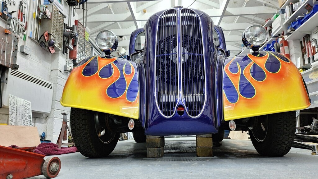
Car stance sitting on the bricks - I think it can go 1/2" lower without issue.
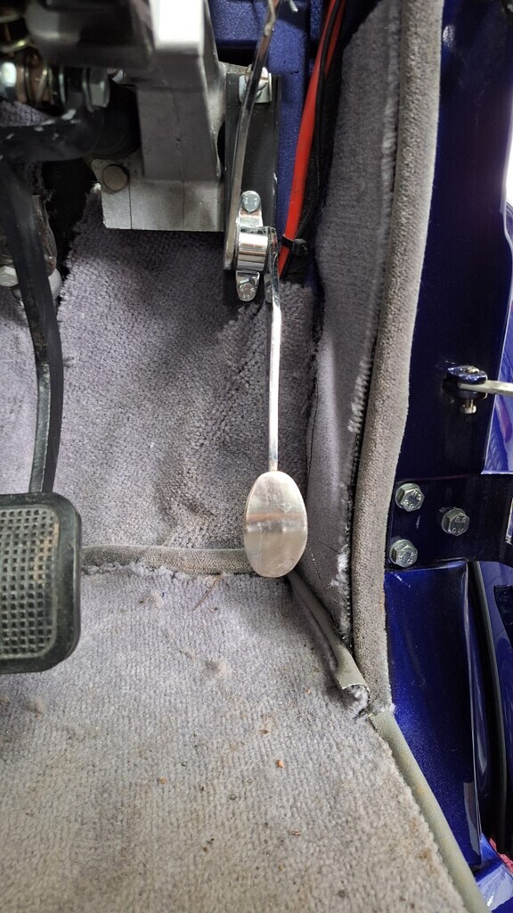
Last job before I came in was the throttle pedal, as you can see, it's too low and too near the A post. (and the cable is completely misaligned to the bulkhead)
A little bit of reworking to the bracket and it's now aligned with the bulkhead so the cable runs straight, and it's move up and in, a far more comfortable foot position. 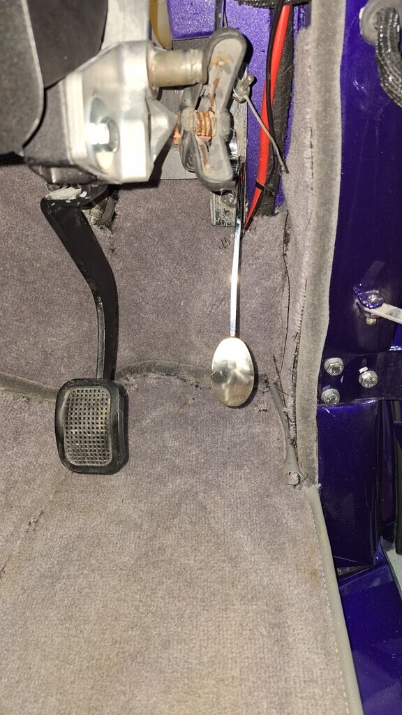 |
| |
|
|
|
|
|
|
|
Apr 15, 2024 22:55:24 GMT
|
Look like Granada Mk1/2 uprights and balljoints to me. Possibly P100 Cortina style. What PCD are the hubs? Cheers, I'll check the PCD tomorrow. Some better shots of the oprights & calipers for identification; 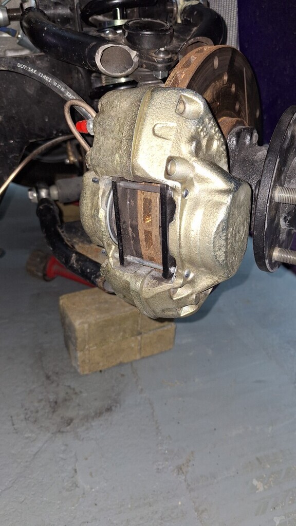 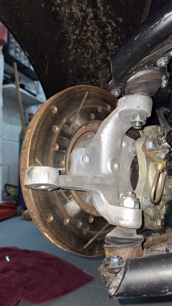 |
| |
|
|
Darkspeed
Club Retro Rides Member
Posts: 4,882
Club RR Member Number: 39
|
|
|
|
That rack is a shocker - So many things wrong about how that has been modified. The uprights are MK3/4/5 Cortina** - Discs are 2.8 Capri vents - Calipers are M16 with spacer plate. The spacers on the caliper bolts will make your caliper hitting the wishbone situation worse. No point in the vents -standard Cortina will be more than good enough - grooved if you want fancy. Sell the vents and calipers and fit stock. Looking at the wipe on the discs - something is up there. As for what has been done to the wishbones and what is going on there! Unfortunately putting it right would be expensive and invasive as all of that mess would need to be removed. The leverage ratio on that bottom arm explains the need for such high poundage springs. As for the amount of compression of the spring its the bump and droop and suspension travel that's the important factors the spring is just a control of those parameters. If it compresses 1-7/8 from droop to chosen ride height - that would be the same for every spring - all that would differ is the amount of preload on the chosen rate of spring. I doubt there is a cheap or easy fix to sort out what you are faced with there. Putting it back together and getting a 4 wheel alignment check and report done would be a good start in giving a datum with which to work off. Until you know what Camber Caster toe and thrust you have you may well be doing work that you will just have to undo later because of unforseen aspects like the chassis being bent or the original suspension not being welded on in the right position to start with. ETA Capri racks are similar to Escort but have a longer input shaft. How many UJ's in the steering - splined, welded, phased? **Correction just seen post suggesting Granada P100 assemblies as they are 5 stud hubs ! That throws a different light on what can be done brake wise as that's a right old mish mash now. Did Grannies have M16s? *** - Or are they, as it looks like they may have been 4 stud re-drilled (badly as the studs fall out)- looking carefully at this picture 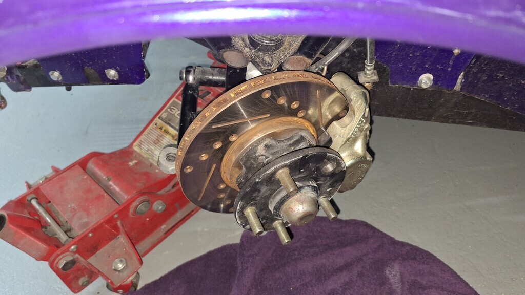 |
| |
Last Edit: Apr 16, 2024 8:04:21 GMT by Darkspeed
|
|
v8ian
Posted a lot
  
Posts: 3,832
|
|
|
|
|
IIRC welding of steering components is not allowed, that rack is plain scary Have an accident due to failure, they will throw the book at you. the steering arms would have been easier to run a die up them and then, shorten as needed. calliper hitting the wishbone, obviously is not ideal, I suppose the obvious option would be grind a wee bit off the calliper, is the issue on both sides? you could take a bit off the mounting spacers and thus move the callipers outboard a smidge, they don't need to be that central to the disc, or event rack stops behind the inner TREs, just a simple spacer on the rack so, on lock the back of the TRE hits the rack body earlier, put the spacers on the rack shaft, not on the threaded part as you will alter the toe.
As Darkspeed says dump the vents, A possibility, as vents on the don't actually improve your braking, all they do is assist is dispersing heat, and help avoid Heat induced fade, another possibility for front hubs are the Mk4 Zephyr Zodiac, they certainly bolt onto a capri stub and give an English 5 stud fitting.
|
| |
Atmo V8 Power . No slicks , No gas + No bits missing . Doing it in style.
Austin A35van, very different------- but still doing it in style, going to be a funmoble
|
|
mk2cossie
Club Retro Rides Member
Posts: 3,062  Club RR Member Number: 77
|
|
|
|
That rack is a shocker - So many things wrong about how that has been modified. The uprights are MK3/4/5 Cortina** - Discs are 2.8 Capri vents - Calipers are M16 with spacer plate. The spacers on the caliper bolts will make your caliper hitting the wishbone situation worse. No point in the vents -standard Cortina will be more than good enough - grooved if you want fancy. Sell the vents and calipers and fit stock. Looking at the wipe on the discs - something is up there. As for what has been done to the wishbones and what is going on there! Unfortunately putting it right would be expensive and invasive as all of that mess would need to be removed. The leverage ratio on that bottom arm explains the need for such high poundage springs. As for the amount of compression of the spring its the bump and droop and suspension travel that's the important factors the spring is just a control of those parameters. If it compresses 1-7/8 from droop to chosen ride height - that would be the same for every spring - all that would differ is the amount of preload on the chosen rate of spring. I doubt there is a cheap or easy fix to sort out what you are faced with there. Putting it back together and getting a 4 wheel alignment check and report done would be a good start in giving a datum with which to work off. Until you know what Camber Caster toe and thrust you have you may well be doing work that you will just have to undo later because of unforseen aspects like the chassis being bent or the original suspension not being welded on in the right position to start with. ETA Capri racks are similar to Escort but have a longer input shaft. How many UJ's in the steering - splined, welded, phased? **Correction just seen post suggesting Granada P100 assemblies as they are 5 stud hubs ! That throws a different light on what can be done brake wise as that's a right old mish mash now. Did Grannies have M16s? *** - Or are they, as it looks like they may have been 4 stud re-drilled (badly as the studs fall out)- looking carefully at this picture  You may be on the right track here. The uprights look similar to mk1 and 2 Granada, but those hubs definitely aren't. Possibly mk3/4/5 Cortina, as the disc to hub appears to be 4 stud |
| |
|
|
|
|
|
|
|
|
I'm pretty sure Darkspeed is correct that the uprights and hubs are Cortina, MK4 or 5.
|
| |
|
|
|
|
|
|
|
Thanks for all the input everyone. I had a thought this morning. As I have almose zero budget to fix this swapping out components is not happening. What I'm thinking is to make all new wishbones with the balljoints mounted a lot lower in the wishbones (so effectively dropping the spindles/raising ride height). This will keep the wishbones level. This will make the caliper/wishbone interference worse, but I think there is good scope to change thre rear of the lower wishbone shape to allow clearance. Issues with this are the rack may need dropping as well (I believe this cannot happen due to space constraints) so some form of drop link for the track rod ends will sort this. I'll set up castor/camber as I make new arms. (drivers side at present has about 4 times the passenger side camber  ) Yes, the wear pattern on the discs is not very good, but it's only done 90 motorway miles so far so may just not be bedded in yet. The short drive I did in it the brakes seemed to work well. |
| |
|
|
|
|
|
|
|
|
I agree with the Cortina uprights and re-drilled hubs that Darkspeed suggested. Having thought about it, Granada hubs have 5 bolts visible on the face for disc mounting.
|
| |
'57 Austin Cambridge A55 1800 Overdrive
'50 MG Y-type (In build)
'56 Standard Super 10 (In build)
'04 Seat Leon TDi 130 (Wet weather runabout)
'03 Citroen Berlingo HDi (Parts hauler)
|
|
|
|
|
|
|
Darkspeed, I'm thinking this would also be ok? 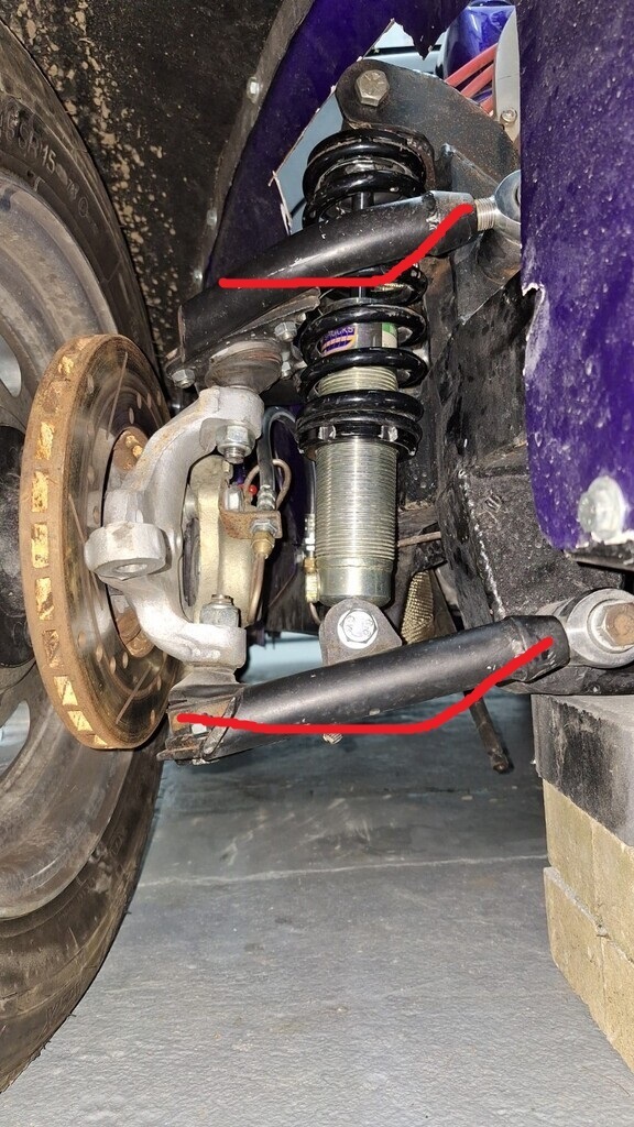
|
| |
|
|
Darkspeed
Club Retro Rides Member
Posts: 4,882
Club RR Member Number: 39
|
|
Apr 16, 2024 10:48:26 GMT
|
|
There is no benefit to the geometry by moving the ball joint higher or lower in the wishbones. It just changes an aesthetic. Any change on ride height is due to moving the lower shock pivot point. The geometry is between the inner pivots and the centre of the ball joint. You may as well go for the easiest way of getting the clearances and angles rather than complicating matters. If you can make a visual improvement why not but, I would not prioritise it as it make no other difference.
As you cannot change anything with the basic geometry without chassis surgery there "should" be no need to move the rack.... if it was right to start with!
A Maxi ball joint has a smaller mount area (Just two bolts) than the Cortina lower type which may allow you more freedom with the lower wishbone shape to narrow it for Caliper clearance.
As the old adage goes - No good deed ever goes unpunished....
|
| |
|
|
|
|
|
Apr 16, 2024 11:20:29 GMT
|
|
With regard to the spring rate you can spend ages weighing things and calculating lever arm lengths etc but I prefer to work with what is in front of you.
Assemble front end complete but without springs fitted.
Let car down to the bump stop on the coil overs, checking nothing else limits travel in the system.
Measure from a point of the chassis at the front axle line to the ground = Dimension A
Jack car up to the top limit of the coil over travel, checking nothing else limits travel in the system. Use a piece of card under the wheel to check when it just lifts of the ground
Measure from the point of the chassis to the ground = Dimension B
Subtract Dimension A from Dimension B = total suspension travel
Refit the front springs (of a known rate) and snug the coil over adjuster up until the spring is just held in place.
Let the car down until it sits at a ride height.
Measure from the point of the chassis to the ground = Dimension C.
Difference between dimension B and dimension C = static deflection. You want static deflection to be about 40 to 50 percent of total travel.
The percentage difference between actual deflection and desired deflection gives an indication on how to change the spring rate.
You need to be happy with the ground clearance dimension A at the fully deflected state. If not something else needs to change, not just the spring rate.
The spring length needs to be such that the coilover reaches the bump stop before the springs go coilbound in compression.
The ride height can be adjusted by moving the spring perch but this does not change the spring rate, only the ride height.
|
| |
Last Edit: Apr 16, 2024 11:34:01 GMT by Fred W B
|
|
|
|
|
Apr 16, 2024 11:24:37 GMT
|
|
Thanks Andrew,
There is some benefit in levelling off the upper arm as it gives more clearance for the spring.
If I can use smaller footprint balljoints that will help matters a lot.
The rack (should??) be dropped as if I effectively drop the spindles on the wishbones (by making lowering platforms for the balljoints) then the rack should be dropped by the same amount - or should it?? - or am I overthinking it?
The rack is actually in the correct place for the suspension as it stands right now. Apart from the car being too low, the suspension (apart from the balljoints bottoming out on droop and the calipers hitting, the shocks being misaligned & springs fouling the wishbones) actually works about right.
|
| |
|
|
|
|
|
Apr 16, 2024 11:47:46 GMT
|
|
One theory on the rack position is that ideally you want the end of the rack positioned on a line drawn between the inboard wishbone pivots, and the same proportion from each as the end of steering arm is from the top and bottom pivots on the upright.
|
| |
|
|
|
|
|
Apr 16, 2024 12:19:48 GMT
|
Fred, I think if I effectively just drop the uprights on the wishbones then the rack does actually remain in the correct geometry (the inner wishbone & steering knuckle points remain in the same pivot point - that bit is at least correctly built). Darkspeed, this is my thoughts on the upper arm - it's only a crude cad drawing from assumed dimensions but it shows the principle of my idea. the lower one would be similar as long as it allows for full steering movement etc. Top view & end view showing the lowered position of the balljoint. If I can do this it keeps the suspension in the parameters it was built for but effectively lowers the spindle height on the suspension - hence raising the car. This will still allow the correct spring travel/poundage. 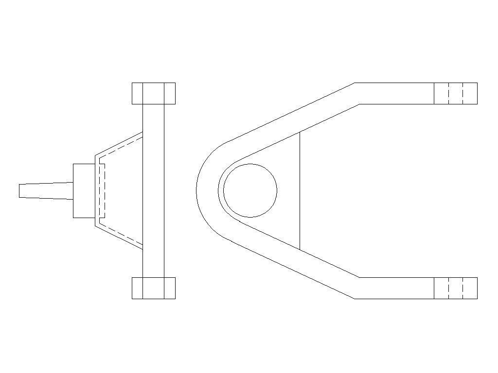 |
| |
|
|
Darkspeed
Club Retro Rides Member
Posts: 4,882
Club RR Member Number: 39
|
|
Apr 16, 2024 12:50:07 GMT
|
Thanks Andrew, There is some benefit in levelling off the upper arm as it gives more clearance for the spring. If I can use smaller footprint balljoints that will help matters a lot. The rack (should??) be dropped as if I effectively drop the spindles on the wishbones (by making lowering platforms for the balljoints) then the rack should be dropped by the same amount - or should it?? - or am I overthinking it? The rack is actually in the correct place for the suspension as it stands right now. Apart from the car being too low, the suspension (apart from the balljoints bottoming out on droop and the calipers hitting, the shocks being misaligned & springs fouling the wishbones) actually works about right. Levelling the top arm - You could get the same result and test the theory by just putting a spacer block between ball joint and wishbone - some simple tubes connected by plates. Just fit spacer tubes for a test. Does not change the geometry. You are not dropping the spindle/axle at all, effectively or any other way - The change in the wishbone makes no change to the geometry. You can only change the geometry by moving the inner chassis pivots in relation to the chassis, or the position of the ball joints in relation to the spindle - You are not doing any of those. All pivots remain in the same positions/locations The geometry is defined by a straight line between the pivots - the wishbone can be the shape of a Pretzel - makes no difference to the straight line between the pivots.ETA - That would be a much nicer and better looking wishbone than what is fitted and will provide some much needed clearance on the spring- but that's the only difference it would make. Same with a lower. If you can move the shock/spring pivot it would make no change to geometry but may mean you can fit a lower spring rate for the same effective spring rate. |
| |
Last Edit: Apr 16, 2024 13:03:41 GMT by Darkspeed
|
|
|
|
|
Apr 16, 2024 13:32:43 GMT
|
|
when You were talking about narrowing the rack I couldn't see how anyone voild get it bent, I assumed it would have been thrown in a lathe and had the end re-machined a 1/2 hours job, can't imagine why on earth anyone would try to cut and weld it!
The Lotus elan used very short steering arms, the rack is triumph based but they may swap over.
I have solid Cortina discs on my TR7V8 never had any problems with fade.
The real problem here is the lack of space, an MX5 upright is quite a bit more compact and might solve many of the issues.
|
| |
|
|
|
|
|
Apr 16, 2024 14:38:14 GMT
|
kevins, yes machining the end is far easier/better, same for the TRE ends. Darkspeed , This crude drawing shows how I mean to drop the spindles to increase ride height. I get where you are coming from with the geometry. I remember when I designed my strut front end - it took 7 weeks of cramming on suspension design to understand that suspensions are incredibly complicated! New design on left - current design on right.
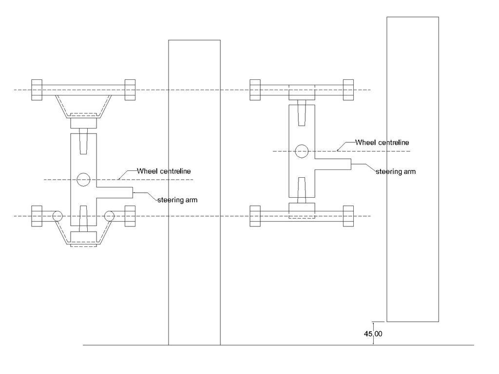
|
| |
|
|
|
|
|
Apr 16, 2024 14:46:24 GMT
|
One bit I can't work out is why all 4 wishbones have been fitted with the rose joint spacers at the back but the rose joints are tight at the front? Why not fit thinner spacers both sides??? I will rectify this as I see no reason not to.

If this was only done on the top wishbones, it would add a tiny amount of caster. If it's been done on both, then you're right - makes no sense/difference at all! |
| |
Living vicariously through other people's projects!
|
|
Darkspeed
Club Retro Rides Member
Posts: 4,882
Club RR Member Number: 39
|
|
Apr 16, 2024 15:05:11 GMT
|
|
Mark,
Is it possible to increase the track by an inch or more each side? Giving a bit more room to play with when you make up the wishbones. Wheels look a long way in the arches - I realise its "a look" but...
The comment that there is only an inch of droop available from ride height is a concern - As Fred describes - Ideally you want the suspension at rest to be around the midpoint of total travel - on a custom set up that may only be 5" total travel with 2.5" each way - a typical set up would be something like 6" travel with 3" down and 2.25 up before touching the bump stop and full compression of the stop at 3"
Probably worth doing some measuring and plotting the pivots and the C/L of the tyre contact patch in Cad to make it easier to visualise what's going on and if it can be corrected.
From what I have read so far the only way to resolve the issues is to cut the chassis and drop that front crossmember something like 4".
|
| |
|
|
Darkspeed
Club Retro Rides Member
Posts: 4,882
Club RR Member Number: 39
|
|
Apr 16, 2024 15:12:17 GMT
|
|
What's the block on the right of each ?
The wheel centre line is the datum that does not move so line them up - And also leave the inner pivots in the same place as They will not move - all you will change is the angle of the wishbone nothing else moves.
|
| |
|
|








 )
)


