|
|
|
Mar 15, 2023 18:12:12 GMT
|
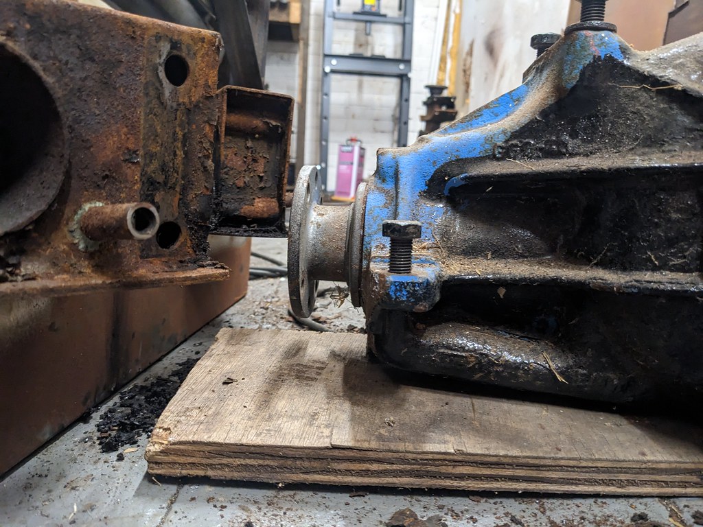
Right! Rack mounts. After a bit of measuring and cleaning up some 5mm sheet the previous occupant had left in the garden I could start mocking bits up. Cad template turned into this:  Spent a lot of time measuring the location of the rack relative to the now-flipped centre of the crossmember. It wound up being 98mm from the upper face closest to the rack to the outermost point of the centre rack tube, in case anyone's thinking of doing the same thing. Bolt another bit on the bottom of the rack and clamp the rack in place like so:  Bit of welding and grinding and we end up with this:   I'll clean up the welds in the centre as soon as I work out what I've done with my carbide burrs... On the other side I had to move the repurposed mounts a little outboard as the bolts fouled on the turret of the rack, but other than that it was the same thing again.   ...and we end up with this    Saves maybe 20mm of clearance over the old mounts, which hang well down below the rack. Next step was to see if my measurements were anywhere near right and it fits underneath the engine. Did a bit of repair work on the mounting surfaces where I'd mistakenly clearenced them where I didn't need to:  ...did a bit more clearancing of the sump...  ...and bunged it all in there! 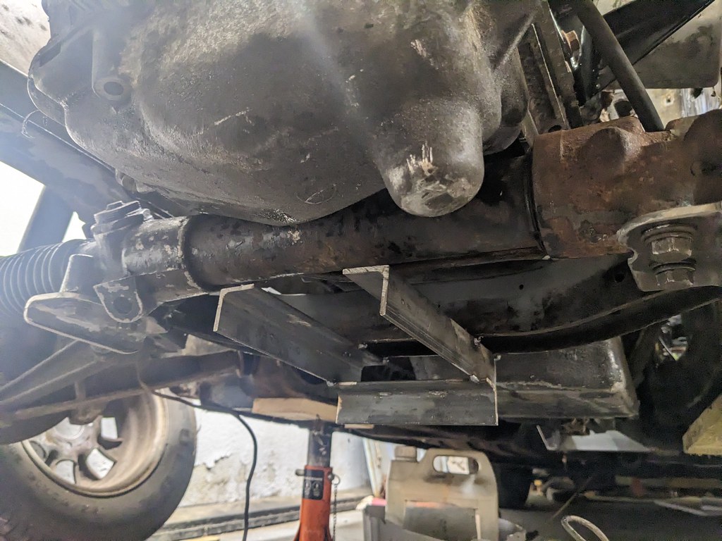 It fits, but it's tight!  In a pleasant surprise, it's not actually the lowest point on the car at the moment. The bottom of the rack is spot on 2mm higher than the bottom of the sump:  This probably means that the engine mount rubbers have compressed more than I'd thought, which is a good thing. Pending bonnet clearance I might be able to shim them up a bit and sneak another couple of mm clearance above the rack. But still, great success!  |
| |
|
|
|
|
|
|
|
Mar 21, 2023 18:06:52 GMT
|
|
I know i may have missed it but how far different in height and fore 'n' aft is the rack position from the original? I was thinking about bump steer and how the new rack position might affect it?
Of course having a steering rack is far preferable to not having a steering rack at all........
|
| |
|
|
|
|
|
|
|
|
|
Apr 12, 2023 12:48:55 GMT
|
|
Nice work.
Ref Steering: If the arm from the rack to the steering arm changes that will change the bump steer (better or worse) In an ideal world the track rod arm is parallel to the bottom arm or virtual bottom arm if an A Frame. Moving the rack down 57mm could improve the angles.......
It's always a trade off putting a different engine in. On my AJ30 installation i have room to move the rack - slightly - to improve bump steer but no room for an exhaust manifold for example!!
|
| |
|
|
|
|
|
|
|
Thanks guys! Interesting. I bet I could take some measurements and work out what the difference in length would be relative to the lower arm. Must read up on how it all works again. I know you want the effective arm of the tie rod to follow the same arc as the wishbone, but I forget quite how to measure it (although if Binky decided the iterative method was easier then perhaps measuring only gets you so far). Have you considered exhausts straight out the bonnet?  Little more shuffled along with the Triumph. As standard it came with a single circuit brake system which I'm none too keen on. You can get tandem masters for Stags which fit, but they've got an odd valve/sensor gubbins in them that causes issues so I thought I'd plump for a manual setup with twin masters and a bias bar. The usual way to do this is with a bias conversion kit like this, but they've got mightily expensive lately (and were never terribly affordable to begin with). So I ended up making this:  Which bolts onto the bulkhead like so:  The bias bar then gets attached directly to the pedal like so:   I ended up having to cut down the tube a fair bit as the masters are quite tightly spaced together (only 60mm apart) to fit through the 90mm opening for the servo. That'll make the adjustment quite fine, but as it's something that rarely needs to be set that should be ok.  Now I just need to cut some 5/16ths threaded rod to length and it's all done  |
| |
|
|
|
|
|
|
|
Right! Long time no post. Turns out that although having a kid is nowhere near as all-consuming as I'd expected, it does still have an impact. Lots done, but in lots of short spurts and not a great deal of big stuff ticked off just yet. Still, getting there slowly. The main project has been the front suspension, starting with the struts.  Turns out it had Koni inserts!  Completely shot mind, so I don't mind having bought a set of GAZ adjustables. Slightly sketchy test of the springs showed they were 157lb/in, which fits pretty well with the 160lb/in stock rate online.  Stripped the struts down with the truly wonderful angle grinder paint removal discs. First time I've use them and they're brilliant. 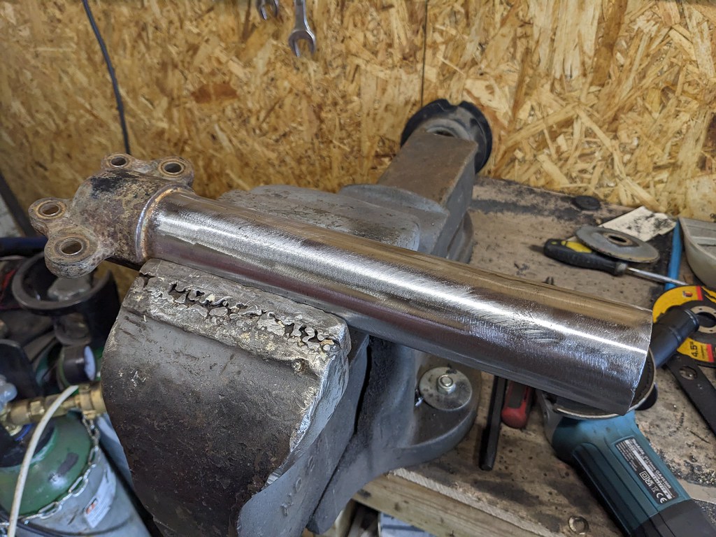 Bought a set of 2.25" coilover conversion kits from RallyDesign just down the road, and a set of 200lb springs. These match the existing aftermarket springs you can get for T2000s, but gives me a bit of an easier time switching around ride heights and different spring rates if need be.  Turns out the GAZ struts are about an inch shorter than standard T2000 struts. Typically people shim them up with spacers dropped into the bottom of the shock, so I've ordered a pair of 15mm long 46mm alloy spacer tubes with a 20mm centre hole. They fit nice and snugly down the strut tube and should locate the bottom of the insert nicely.  I've also tested out some de-rusting acid solution from Bilt Hamber on all the various front suspension gubbins, which took a while on some of the more corroded bits but worked a treat. That's all currently with a local zinc platers being made all shiny   Meanwhile I've painted the lower control arms and subframe. Can recommend Bilt Hamber epoxy mastic as a chassis paint. Seems much better than the POR-15 I've been using previously, which works well when it's gone off slightly but out of the pot it runs off edges leaving them exposed far too readily.   Next up is a set of camber adjustable strut tops from a TR7. You can get these in the right bore for T2000 struts, though I've had to drill out the bottom of the spacer to 19mm for 3mm depth or so to give enough threads poking out the top for me to be comfortable with them. I'll also need to make up a spacer so the spring pan will sit on a proper shoulder in droop, for which I'll need the lathe up and running. 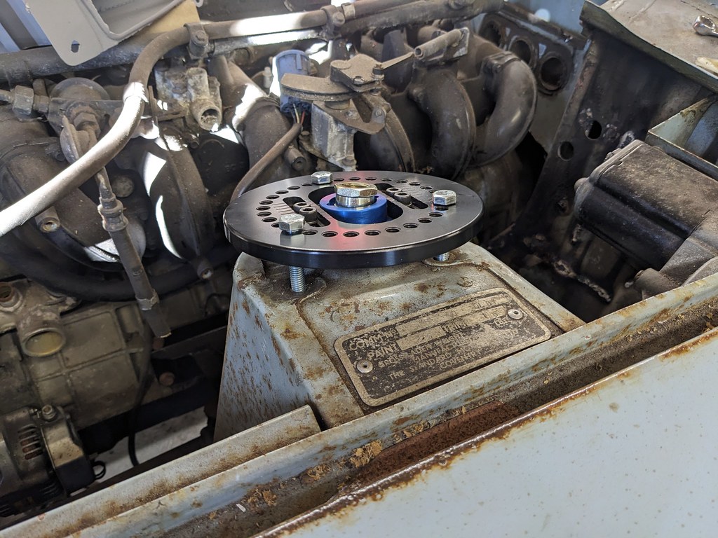 Positively, the boltholes for the strut line up nicely with the slightest tickle of a file. Maybe half a mm per hole which should help keep them in the right position. The OD is too big to fit though, so that's another lathe job... Lastly, because you can never have too many things dismantled all at once, I've pulled the rear suspension off as well ready for the BMW diff swap   Hopefully will be getting some bits built back up again soon! |
| |
|
|
stealthstylz
Club Retro Rides Member
Posts: 14,960
Club RR Member Number: 174
|
1966 Triumph 2000->2500->4000stealthstylz
@stealthstylz
Club Retro Rides Member 174
|
|
|
Turns out that although having a kid is nowhere near as all-consuming as I'd expected I remember that "the baby years" optimism. Seems a long time ago now mine are 14 and 9 and seem to take up all my time lol. |
| |
|
|
|
|
|
|
|
Haha I was expecting more of a cliff-edge but I think a gradual decline is more like it  |
| |
|
|
|
|
|
|
|
|
Depends quite a bit on the baby/child.
First 20 years are the worst…..
|
| |
1967 Triumph Vitesse convertible (old friend)
1996 Audi A6 2.5 TDI Avant (still durability testing)
1972 GT6 Mk3 (Restored after loong rest & getting the hang of being a car again)
|
|
|
|
|
|
|
|
|
Next few bits and pieces progressed, in my usual scattergun approach  First off was a bit of de-rusting on the diff mount. Dragged the subframe assembly out of the car and pulled the mount off: 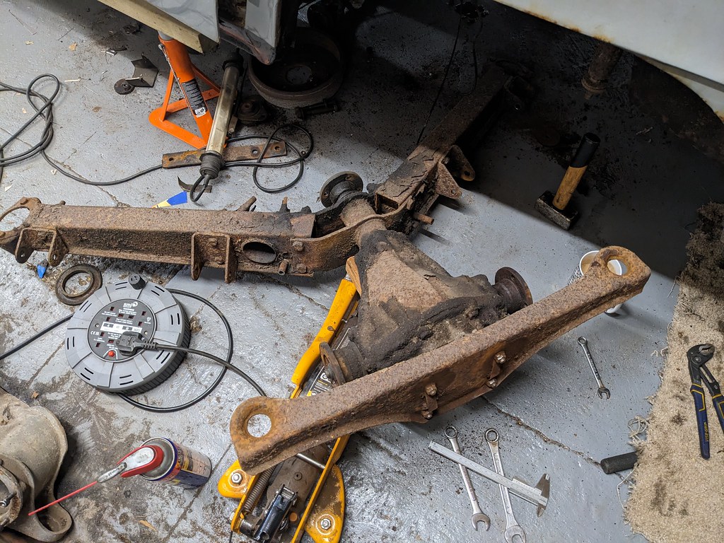  I've bought a bottle of deox c acid rust removal stuff from Bilt Hamber and made it up in a bin. Wonderful stuff! Goes to show how wire wheeling heavily rusted parts still doesn't quite get all the rust out: 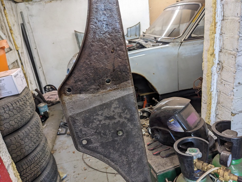 Also managed to pick up an E36 compact subframe for £20 and liberated the diff mount:   Next up was sorting the pedal box. Welding the bias bar into the pedal worked perfectly, but the threaded rod on the master cylinders wasn't quite long enough to reach. What I really need is some 5/16ths threaded, 1-1.25" long hex standoff nuts, but they're not a common fastener it would seem. Ended up tapping some tube and screwing that on using a piece of threaded rod, which gets it all connected while I source some proper hardware.   If I can find a source for the right standoff nuts I might look at getting a batch of the adapter plates made in 6082 aluminium with helicoiled studs. I've done some rough quoting and would probably be looking at £50 each for a batch of 5, or £40 for a batch of 10. Not sure how many takers there would be though, seeing as it would only really fit saloons and stags. The next thing I've been pottering along with is a rear disc conversion. There's been about half a dozen different approaches for TR6s all using a caliper mounting plate that sandwiches between the hub and the trailing arm like so: 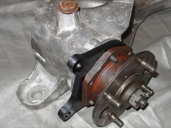 All of them have used discs that needed machining, and often custom handbrake cables. Using the brake disc catalogue I've put together I found that a 258mm Hyundai Coupe disc and a 76mm-70mm spigot ring would work pretty well.  I've picked up a set of MGF calipers, which very nearly fit perfectly just bolted to a flat plate on the back of the hubs, but are out by 2mm.  First iteration of the design had two plasma-cut plates, a caliper mount and a spacer. This would increase the track by 9.5mm each side though, so I switched to a machined plate that looks a little like this:  That only increases the track by 7.5mm a side which is more likely to be within the range of plunge for both the UJ and CV driveshafts. Again, happy to produce a batch if people are interested (after I've tested it works of course!). Looking like £150-200 a pair for those in hard anodised 6082 ally, again depending on batch volume. Would be interested to know if anyone fancies a set. Also happy to share CAD files if they want to make a pair themselves, but commissioning them individually does work out more expensive. |
| |
Last Edit: Nov 16, 2023 21:40:10 GMT by biturbo228
|
|
|
|
|
Jul 14, 2023 21:03:13 GMT
|
|
|
| |
|
|
|
|
|
Jul 17, 2023 11:40:25 GMT
|
Spent a fair while vacillating around about how whether it's better to mount it too low but in the right place fore/aft, or the right height but too far forward, before finally thinking 'I've hacked a great big hole in the floor for the gearbox, why am I concerned about a little bit of clearancing at the back?' So I've spaced the diff forwards by 10mm with some extra nuts and washers: 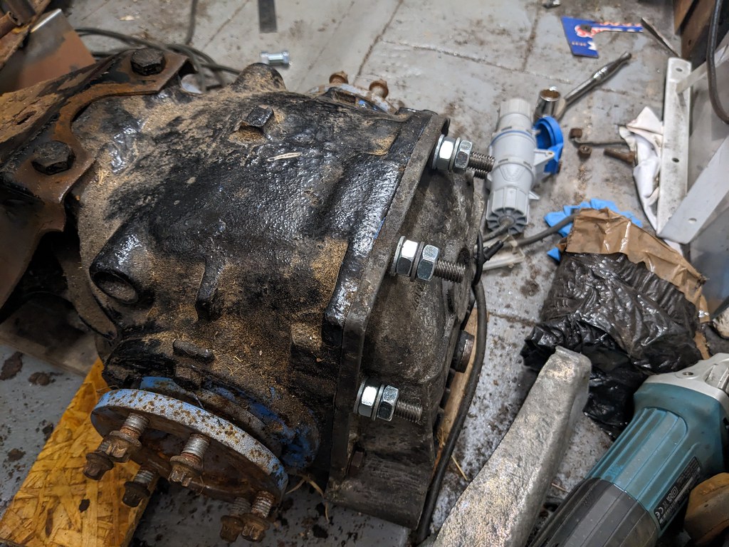 ...welded an extension to the diff plate and drilled yet more holes:  ...and actually put the pinion in a sensible location:  I don't actually think it'll take much clearancing of the floor at all. A little under the middle of the rear seat to get the prop high enough (not an issue if you're using the original gearbox as mine's sitting much higher), and a little expansion of this pre-existing scallop:  |
| |
Last Edit: Jul 17, 2023 16:02:40 GMT by biturbo228
|
|
|
|
|
|
|
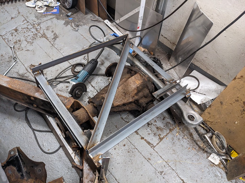
Been plugging away at the rear subframe. I've tried to pay attention to how the forces are fed through the subframe and eyeballed where it'll need reinforcing to resist them. This video gives a good idea of what direction cornering forces are fed into the suspension: So, primarily it'll be using the trailing arm as a lever to push the centre of the subframe forward towards the front of the car. So, big flat plate on top. Needs to be curved to clear the prop though.   It also needs to hold the diff in the right place fore-aft, so welded to the BMW diff mount I've chopped off the compact subframe: 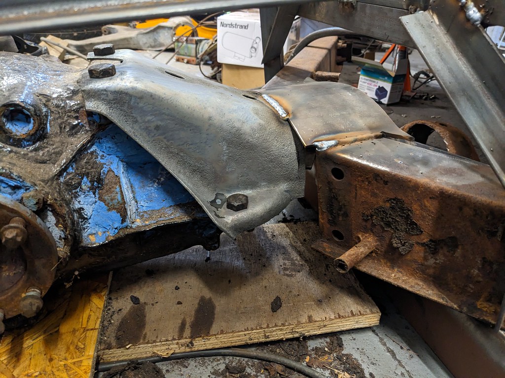 Next thing it'll try and do when suspension forces are put into it is buckle the bent cross-plate upwards or downwards (not sure which). The diff also needs to be supported properly to stop the nose bending upwards or downwards relative to the rest of the car. So, I plated in the back section. The vertical plates will help with the buckling and diff location, and the horizontal plates hopefully feed some of the suspension forces into the diff mounts.   Lastly, with the back side being reinforced it still left the front liable to buckle upwards as it's only a single thickness of 3mm plate, so a stiffening brace went on there too: 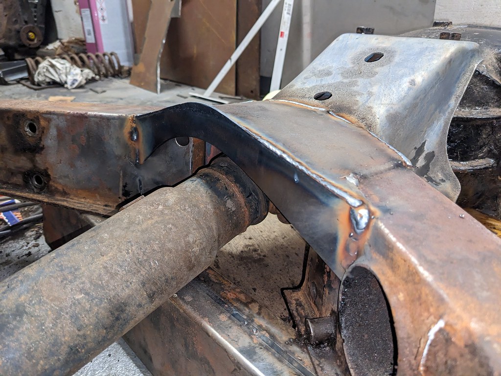 The rear diff mount was nice and stiff vertically, but where I'd cut away a fair bit of the structure to poke the diff up through it you could wag the mounting lugs forward and backwards horizontally a little. So that got a little horizontal bracing over the top of the diff:  This still leaves the underneath of the subframe open and unreinforced, which won't be great for stiffness. However, thanks to the fact that the propshaft will need to go over the top of this box section in the middle of the car...  ...I'll have to be able to drop the tail of the prop under the subframe to get it out. So, I figured a bolt-on reinforcement plate on the bottom would work well. That meant a few captive nuts on both the horizontal and vertical planes:  Finally, that's all the welding sorted and I could remove the jig and the piece of beefy box section I'd welded to the bottom to keep it all true. It did go ping a little, but through all that welding had only distorted by maybe a millimetre (if that) over a 2-foot distance. 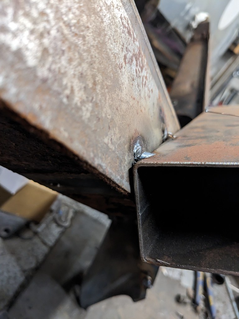 Not bad I think!  |
| |
|
|
|
|
|
|
|
loving your work Simon, that brake bias box looks familiar  |
| |
|
|
|
|
|
|
|
|
Thanks!
Yours is clever setting the master mounting face back a bit to avoid extending the threaded sections.
|
| |
|
|
|
|
|
Sept 4, 2023 11:21:12 GMT
|
Lots of other projects taking up time recently, but I've done a few bits and pieces to the big Triumph. I plopped one end of the subframe in my bin of acid and it came out much more silver than just wire wheeling, and also showed up pinhole I didn't realise was there   So I bought myself some citric acid so I could play at being a drug smuggler... 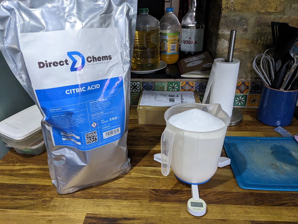 ...and some 120l barrels...  ...so I can now dunk half of the subframe at a time!  It's slower going than the Frosts stuff I've used in the smaller bin, but significantly cheaper for a big barrel. I've also got a barrel of baking soda solution to neutralise the acid where I can't reach to wash it out. I've put about 2kg of citric acid into ~110l of water. We'll see if that concentration works and up it if not (I know our water's quite hard here so it'll start at a more alkaline level than softer water). Eventually I'd like a barrel of phosphoric acid (milk stone remover is the cheap way to buy it in volume) and water as well so I can etch and rinse big things as well, but this will do for now. I've also picked up some rather nice goodies for it   4-pot vented Stag brakes. Nice and light compared to the stock bits. 6.3kg per side (plus pads which they didn't have in stock at the time).    That compares to 10.2kg per side for the Stag setup (discs were a hair over 5kg each)  I've also weighed the rear brake components. Stock T2000 rear drums weigh 6.6kg per side, and my MGF caliper/Hyundai Coupe disc and shiny adapter setup comes in at 7.2kg. A little heavier, but worth it I think to have rear discs that don't need manually adjusting for wear... Oh, and speaking of shiny brake adapters, my prototype set has turned up!   Nicely machined in 6081 ally. The brake mounting tabs are only 8mm rather than 10mm, but I didn't want to push the wheels much further out than that in the arches. Will keep an eye on them to make sure they're not fatiguing... |
| |
Last Edit: Sept 4, 2023 11:23:53 GMT by biturbo228
|
|
|
|
|
Oct 11, 2023 21:38:46 GMT
|
So the subframe has been pickling away. It's quite effective stuff!  Annoyingly it flash-rusted even after popping it in the phosphoric acid tub which usually leaves a layer of iron phosphate on the surface which prevents flash-rusting... 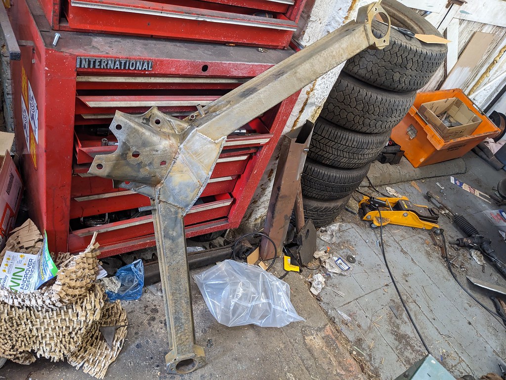 Might be something to do with the strength I have it. I got my measurements wrong and it wound up closer to 4% than 2%. Either way, I'm hoping that a coat of hydrate 80 might sort that out before final paint. Little bit of a weld repair where some rust holes used to be:   Oh, and I need to replace some of the captive nuts as the 4% pickle has done a number on the threads. It's supposed to be somewhat self-limiting so I wasn't concerned about leaving it in there, but not at higher concentrations apparently! Hard to see from my inexpert photo, but the threads are half missing and the exterior of the nut doesn't look too healthy either...  The other side got a much quicker dip and came out better. I've also done the final bits to the backplate, which involved adding tabs down to the lower casing bolts:   ...and repairing one of the mounting ears where it had rusted. Tricky thing to get to to shape the welds, but a carbide burr worked well enough.    Next step is to get it painted and throw it all together to see what floor clearance is like  |
| |
|
|
|
|
|
Oct 12, 2023 17:25:53 GMT
|
|
Always look forward to updates on this one.
|
| |
|
|
|
|
|
|
|
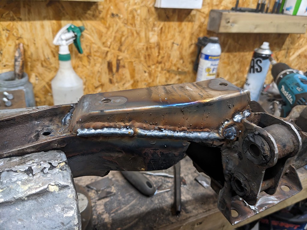
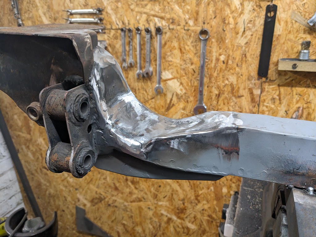
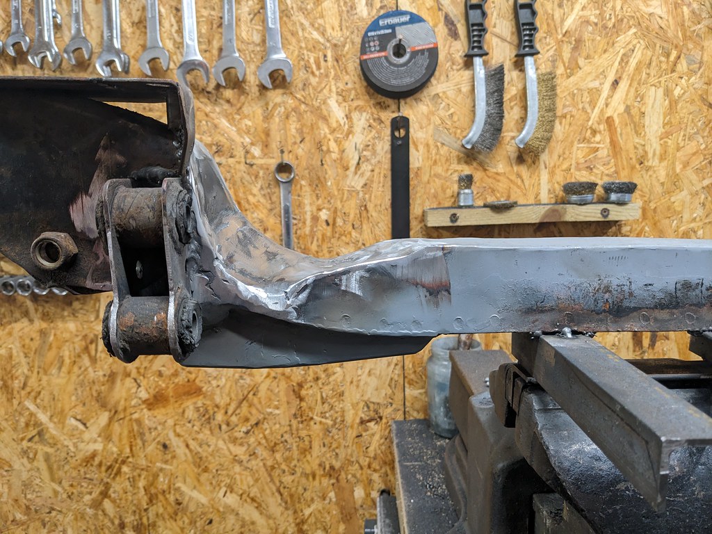
Thanks! It's been a little slow going recently, but steadily chipping away at it. I wasn't 100% happy with the amount of pitting on the rear subframe. Pretty sure it'll have weakened it, which is less than ideal for something that has to take all the rear cornering, braking and acceleration loads. So I chopped up some 2.5mm box section to reinforce it a little.   After that a spot of Hydrate 80 to sort any flash rust from the acid stripping...  ...and some epoxy chassis paint, which really is very good stuff. Always used POR15 beforehand, which works well when it's gone off in the tin a little but really struggles with coverage on corners and high spots when fresh (and doesn't last long once it's gone off enough to work properly). This stuff goes on beautifully.  |
| |
|
|
|
|


