jonomisfit
Club Retro Rides Member
Posts: 1,790
Club RR Member Number: 49
Member is Online
|
|
May 17, 2020 18:51:55 GMT
|
then on to the cross beams. set up on the bench  P1030647 P1030647 by jono_misfit, on Flickr glue it together  P1030648 P1030648 by jono_misfit, on Flickr slowly getting better at tig on ali, although i think i needed slightly higher gas flow and a better clean on the ali, as some contamination.  P1030649 P1030649 by jono_misfit, on Flickr I pulsed the pedal with my foot which made a huge difference  P1030650 P1030650 by jono_misfit, on Flickr theres a pulse weld on the machine, so at some point I may well set that up and try it. I ran out time to finish the second bar as i'd forgotten to cut any gussets for it.... i bolted up what I had to check  P1030651 P1030651 by jono_misfit, on Flickr  P1030652 P1030652 by jono_misfit, on Flickr  P1030653 P1030653 by jono_misfit, on Flickr fit perfectly. I need to finish the rear bar welding, then drill a few relief holes in the centre of them. I'll need to make / mock up the sump guard to see where else i need to weld in some mounts. |
| |
|
|
|
|
|
|
|
May 17, 2020 22:39:11 GMT
|
Huh. That's not as obtrusive as I thought it was going to be. Be interesting to know what the whole guard weighs when done.  |
| |
|
|
jonomisfit
Club Retro Rides Member
Posts: 1,790
Club RR Member Number: 49
Member is Online
|
|
|
|
|
Currently sub 5kg at a guess.
I'm interested how much the car will weigh in the end!
|
| |
|
|
|
|
|
|
|
|
Are you putting lexan in it?
|
| |
|
|
jonomisfit
Club Retro Rides Member
Posts: 1,790
Club RR Member Number: 49
Member is Online
|
|
|
|
|
Side windows and doors will be.
I'm going to give the doors a good going over as they weigh a ton.
I'm not sure what's adding all the weight to them.
|
| |
|
|
|
|
|
|
|
I know you know what you are doing with fab work but?
I know this will sound a stupid question to some but have you thought about where the impact forces will go if there is a semi substantial impact in this area? I know you have done stress analysis for your other car have you for these lower front end parts, would it not be better to make a deform able easy to make part that will take the impact rather than not bend/deform and send the impact force just into another part of the cars structure? Those aluminium side pates are quite thick and look very expensive and will either crack or bend the structure around them rather than dissipate any impact force. |
| |
Last Edit: May 18, 2020 9:11:38 GMT by peteh1969
|
|
jonomisfit
Club Retro Rides Member
Posts: 1,790
Club RR Member Number: 49
Member is Online
|
|
|
|
|
All valid points worth considering.
These are the same design of sump guard mounts used on escort cosworth rally cars by the rally teams from the 90s onward. They changed on the wrc cars, but effectively pick up on the same rear two mounts points.
The thing with the sump guard is you really don't want it moving much. There's not normally a huge distance between them and important parts like radiators and sumps. If they move you'll break something more important.
You can live with the front of the chassis legs twisting a bit on a rally, but not loosing a radiator / sump.
The sump guard is also meant to deflect stones and ride you over an obstacle with the weight of the car on it, so the support needs to be pretty robust.
There are also additional mounts further back along the legs so it's supported further back as well.
Like all things rally it's a balance between survivability and performance.
If you hit something hard enough to damage the leg where the sump guard mount is, there's a good chance you've ended the rally from other damage in the crash.
|
| |
|
|
|
|
|
|
|
|
Ok fair enough, do you intend to use it as a full blow rally car when you are done then?
|
| |
|
|
jonomisfit
Club Retro Rides Member
Posts: 1,790
Club RR Member Number: 49
Member is Online
|
|
May 18, 2020 10:47:44 GMT
|
Ok fair enough, do you intend to use it as a full blow rally car when you are done then? Not really. I was going to but having seen the way prices have gone on decent rally parts now for escorts I don't think I can afford to. They are bonkers! It's more going to end up being a fun car for using round the lanes and track days. ..... which does really bring in to question why I'm even fitting a sump guard.... but shhhh don't use logic on me 😁 Some of the lanes round here are pretty rough condition so it will have some use |
| |
Last Edit: May 18, 2020 10:49:00 GMT by jonomisfit
|
|
jamesd1972
Club Retro Rides Member
Posts: 2,921  Club RR Member Number: 40
|
|
May 18, 2020 17:06:19 GMT
|
|
You can also go for super lows....
Anyway 'because I want to' is more than enough reason round here !
Nice progress, thanks for sharing.
James
|
| |
|
|
jonomisfit
Club Retro Rides Member
Posts: 1,790
Club RR Member Number: 49
Member is Online
|
|
May 20, 2020 20:09:45 GMT
|
|
i welded on the other reinforcing triangles tonight and bolted back up to the car. ice and solid.
Then chucked the wings and bumper on. The mount has the sump guard just above the bottom of the bumper.
I R relieved. I was was a bit concerned that I'd fit it in the wrong place (no dimensions) and the sump guard would be low and stick down a long way under the bumper. Looks like my looking at a lot of pictures on the web paid off.
I'll put some pics up on the weekend.
|
| |
|
|
jonomisfit
Club Retro Rides Member
Posts: 1,790
Club RR Member Number: 49
Member is Online
|
|
May 20, 2020 20:10:18 GMT
|
You can also go for super lows.... James I can defintiely go for lows in safety now. |
| |
|
|
jonomisfit
Club Retro Rides Member
Posts: 1,790
Club RR Member Number: 49
Member is Online
|
|
May 22, 2020 19:58:49 GMT
|
Bumper roughly in position  P1030654 P1030654 by jono_misfit, on Flickr It really is not a great fit. ducking below parallell and you can see the sump guard mounts.  P1030655 P1030655 by jono_misfit, on Flickr Sump guard will tuck up just behind the lower part of the bumper I don't have propper mounts, need to make some. Sketch.  P1030656 P1030656 by jono_misfit, on Flickr cut some box  P1030657 P1030657 by jono_misfit, on Flickr cut some sheet  P1030658 P1030658 by jono_misfit, on Flickr go here like so. bolts on to m6 nuts bonded in manufacture. I had to dig a lot of resin out, and put a tap down the nuts. 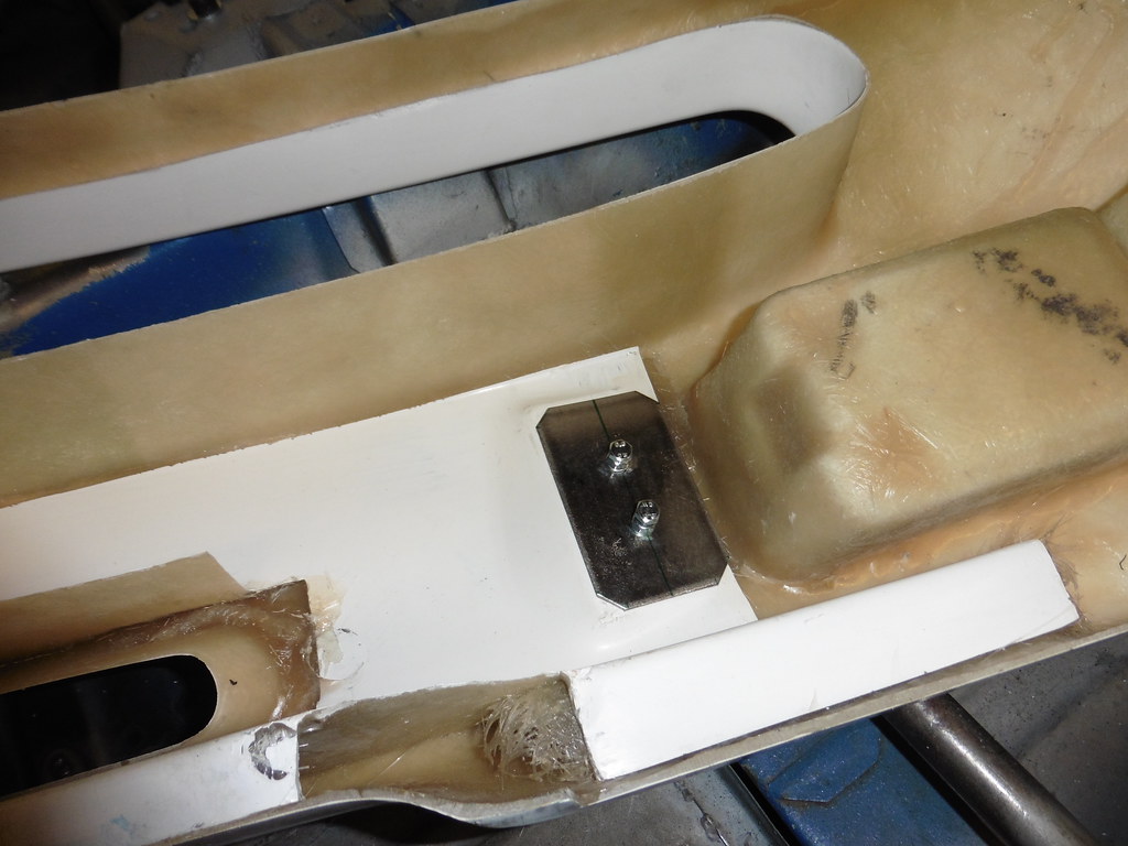 P1030659 P1030659 by jono_misfit, on Flickr  P1030660 P1030660 by jono_misfit, on Flickr add some nuts to the box section  P1030661 P1030661 by jono_misfit, on Flickr make up some of these tabs  P1030662 P1030662 by jono_misfit, on Flickr go together like so  P1030663 P1030663 by jono_misfit, on Flickr stiffen the bumper plates  P1030664 P1030664 by jono_misfit, on Flickr go on like so  P1030665 P1030665 by jono_misfit, on Flickr tigged together  P1030666 P1030666 by jono_misfit, on Flickr will go together like so  P1030667 P1030667 by jono_misfit, on Flickr added a washer one end and a nut the other  P1030668 P1030668 by jono_misfit, on Flickr bolted through  P1030669 P1030669 by jono_misfit, on Flickr fitted and bumper back on the car. Passenger side lines up great.  P1030670 P1030670 by jono_misfit, on Flickr drivers side does not. 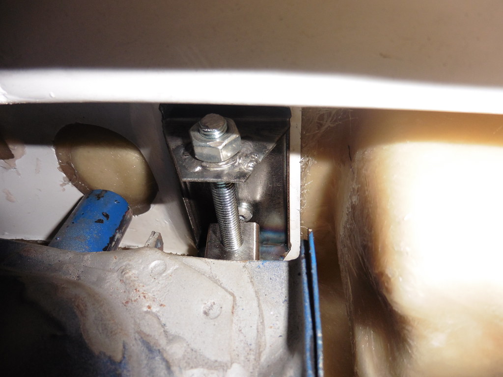 P1030671 P1030671 by jono_misfit, on Flickr I think the mounts for the bracket are about 5 - 10mm offset. Which means the nuts are fitted off centre in the bumper. I can "make" the bolt holes line up in the chassis leg, but its not a good idea to do to fiberglass as it'll just crack with time. Not the end of the world though as I can slot the mounting brackets holes to move it over a bit to align. Will see what sunday brings. |
| |
|
|
jonomisfit
Club Retro Rides Member
Posts: 1,790
Club RR Member Number: 49
Member is Online
|
|
May 24, 2020 19:22:36 GMT
|
I took the bumper back off, removed the bracket, slotted the holes in the mill over 10mm, then tigged on some washers where the rod goes through the 25mm box and re-fitted. Not easy to see, but it now lines us straight to the chassis rail.  P1030672 P1030672 by jono_misfit, on Flickr there's a fair bit on float on the front of the bumper, so i'll add a couple fo lock nuts when I come to fit it propperly.  P1030673 P1030673 by jono_misfit, on Flickr and the other side  P1030674 P1030674 by jono_misfit, on Flickr I cleaned back the roof seams and filled a few small holes, then cleaned them back  P1030675 P1030675 by jono_misfit, on Flickr  P1030676 P1030676 by jono_misfit, on Flickr seam welded the remaining seam at the rear  P1030677 P1030677 by jono_misfit, on Flickr then changed my attention to the front wings. Drivers one had some decent dents / gouges in it, so spent a bit of time dressing back  P1030678 P1030678 by jono_misfit, on Flickr the rust lines to the left are where the gouges were.  P1030679 P1030679 by jono_misfit, on Flickr Not 100% perfect, but substantially better than they were. lower rear wing mount is getting a bit thin, the mounts have come off, and its bent out of shape  P1030680 P1030680 by jono_misfit, on Flickr  P1030681 P1030681 by jono_misfit, on Flickr Straightened up  P1030682 P1030682 by jono_misfit, on Flickr  P1030683 P1030683 by jono_misfit, on Flickr made a template, marked some steel  P1030683 P1030683 by jono_misfit, on Flickr trimmed back the grotty piece of wing  P1030685 P1030685 by jono_misfit, on Flickr then tigged it on. I used the tig as it'll need some dressing back once on the car, and I don't want to try plannishing rock hard mig welds. Not the easiest thing for me butt welding super thin (0.7ish mm) steel with the tig, but got a technique together in the end  P1030686 P1030686 by jono_misfit, on Flickr ready for dressing back / hammering  P1030687 P1030687 by jono_misfit, on Flickr drilled all the wing holes and fitted riv nuts, then bolted the wing on  P1030688 P1030688 by jono_misfit, on Flickr clamped the lowesr edge into position ready for drilling (also shows why the wings rot there. A nice dirt trap and a flat surface  P1030689 P1030689 by jono_misfit, on Flickr drilled the holes through  P1030690 P1030690 by jono_misfit, on Flickr  P1030691 P1030691 by jono_misfit, on Flickr the rearmost fixing is through 3 skins. Will see how it holds. If it starts slipping i'll probably fit a steel riv nut and tig it in.  P1030693 P1030693 by jono_misfit, on Flickr bolted up, then started dressing the dents a bit more  P1030692 P1030692 by jono_misfit, on Flickr then turned my attention to the other wing  P1030694 P1030694 by jono_misfit, on Flickr this bit really irritates me. They just painted over the wing vents. The things are held in with pin centre fasteners. It takes <30 seconds to remove them.  P1030695 P1030695 by jono_misfit, on Flickr  P1030696 P1030696 by jono_misfit, on Flickr#  P1030698 P1030698 by jono_misfit, on Flickr  P1030699 P1030699 by jono_misfit, on Flickr I'll need to look at ways of getting paint off delivate plastics. I get another pair, but they arent common and arent cheap. A NOS on ebay at the moment is £145 for one. Worst case i'll paint it again in black. the mout on the passenger wing had failed ages ago it looks like, and the bottom of the wing has been moving about. Its cracked the wing. Cleaned back and clamped.  P1030700 P1030700 by jono_misfit, on Flickr then gingerly tiged it up  P1030701 P1030701 by jono_misfit, on Flickr  P1030702 P1030702 by jono_misfit, on Flickr a light dress back and it'll be sorted. the bottom of the wing is also very frilly  P1030703 P1030703 by jono_misfit, on Flickr I'd buy another wing, except they are about £400 each second hand, or about the same for a pair of decent quality aramid / grp ones. Will see how i get on with these. The bottom section is covered by the front of the side skirt any roads. marked out where I'll need to cut it  P1030704 P1030704 by jono_misfit, on Flickr But ran out of time. |
| |
|
|
jonomisfit
Club Retro Rides Member
Posts: 1,790
Club RR Member Number: 49
Member is Online
|
|
May 25, 2020 19:33:12 GMT
|
marked up some steel  P1030705 P1030705 by jono_misfit, on Flickr started cutting and folding  P1030706 P1030706 by jono_misfit, on Flickr trimmed the wing  P1030707 P1030707 by jono_misfit, on Flickr these will turn into the stiffening wedges 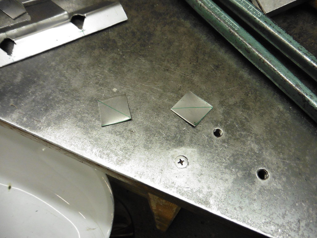 P1030708 P1030708 by jono_misfit, on Flickr test fit  P1030709 P1030709 by jono_misfit, on Flickr  P1030710 P1030710 by jono_misfit, on Flickr welded in and ready to clean back and straighten 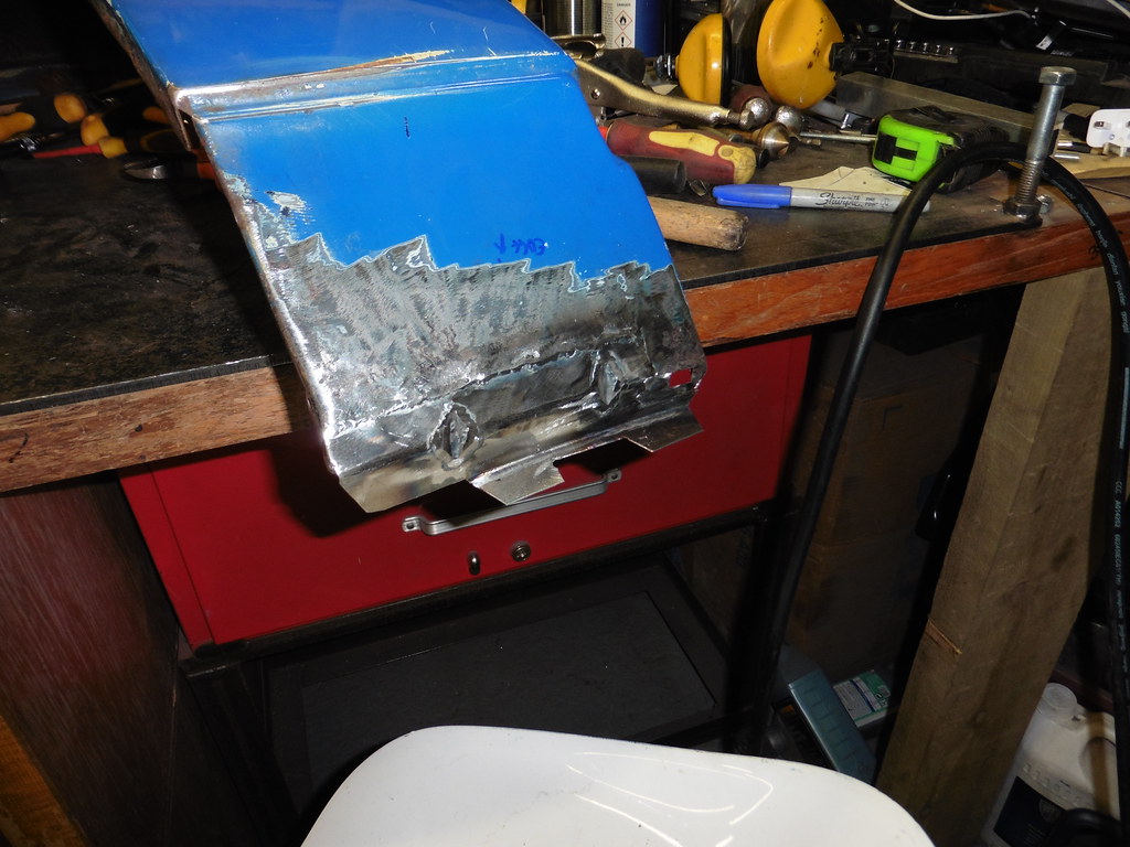 P1030711 P1030711 by jono_misfit, on Flickr front wing mounting had been badly repaired before, so trimmed back and welded in a new piece  P1030712 P1030712 by jono_misfit, on Flickr  P1030713 P1030713 by jono_misfit, on Flickr wing back on  P1030715 P1030715 by jono_misfit, on Flickr bolted down  P1030716 P1030716 by jono_misfit, on Flickr someone in the factory had gone mental with the spot welder on the front of the wing. There were 4 additional spot welds v's the other side. rivnuts in and all bolted up  P1030717 P1030717 by jono_misfit, on Flickr car back on the spit  P1030718 P1030718 by jono_misfit, on Flickr turned over and time to start looking at the side skirts  P1030719 P1030719 by jono_misfit, on Flickr 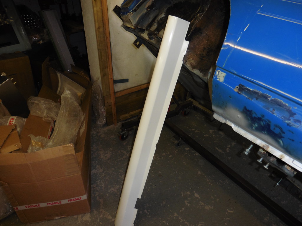 P1030720 P1030720 by jono_misfit, on Flickr this is goign to be a mare as the sill stand tube stick right out and will go through the body kit except i'll have to try and cut holes in thin air with limited reference points. Good chance of c0cking it up and having holes out of position  P1030721 P1030721 by jono_misfit, on Flickr oh. it turns out escort cosworth side skirts are quite deep.  P1030722 P1030722 by jono_misfit, on Flickr hmmm. that leaves me with the quandary. Do I even drill the holes for the sill stands to go through? I'll fit the skirts then decide if I do or not.  P1030723 P1030723 by jono_misfit, on Flickr fixings  P1030724 P1030724 by jono_misfit, on Flickr these go in the bottom of the sill and take a self tapping screw  P1030727 P1030727 by jono_misfit, on Flickr these push into all the little nylon bungs in the upper part of the sill  P1030728 P1030728 by jono_misfit, on Flickr and sit like so. 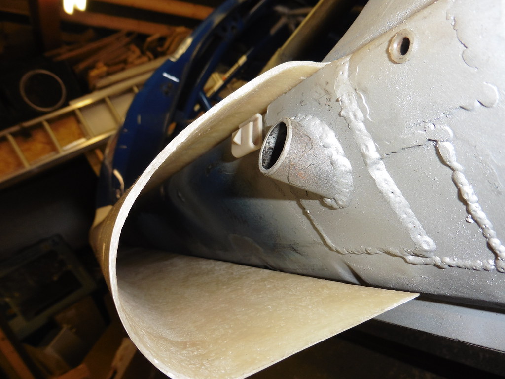 P1030729 P1030729 by jono_misfit, on Flickr I assume on genuine sills there is a little lip that clips into the top. I don't have this feature, and most of my clips are broken. I'll affix a differenet way. good quality moulding, comes with feature marks   P1030730 P1030730 by jono_misfit, on Flickr  P1030731 P1030731 by jono_misfit, on Flickr I checked alignment with the mounts... just in case... then drilled out fitted the sill  P1030731 P1030731 by jono_misfit, on Flickr and drilled the two in the wing to 6mm (were rivets before) for a nut / bolt. There's not enough land for a rivnut, so will see about getting a threaded spire spring clip. added a few self tappers to the top to hold, may see about using riv nuts instead. Although this seems to be the rally approach to the sills. the skirts really do set the look  P1030734 P1030734 by jono_misfit, on Flickr  P1030733 P1030733 by jono_misfit, on Flickr |
| |
|
|
|
|
|
May 25, 2020 23:14:52 GMT
|
|
i have an idea for your jack stand problem
could you not turn a bung on the lathe so it goes into the i/d jack stand with the same o/d as the jack stand tube, cut the end of the bung at the same angle as the skirt and maybe saw / mill a flat for reference a bit of faff to make but it would remove the fresh air
|
| |
|
|
|
|
|
|
|
|
I was going to ask if you're going to keep the stands feature.
Get a Sharpie mounted in the pipe so it can slide in as you clip the sill on, and then it will leave a mark for you to pilot hole your access hole to?
Or similar.
Then what, extend the stand pegs so they clear the sills properly and put a bung in the sills?
Or are you going to remove the sills to put it on stands?
|
| |
|
|
|
|
|
|
|
Jon - Don't know if you know of this supplier for vehicle trim clips - but if not you may find them useful with either of your builds bresco.com/ |
| |
Last Edit: May 26, 2020 16:45:29 GMT by Deleted
|
|
jonomisfit
Club Retro Rides Member
Posts: 1,790
Club RR Member Number: 49
Member is Online
|
|
|
|
|
Thanks for the suggestions.
If I'm going to cut the holes I'll probably turn a bung to go in the tubes with a sharpy in the centre of it.
It'll give a centre point I can drill from.
The support stands have a long pin on them, so them sticking out an extra 20mm to clear the skirt will be neither here nor there.
There are only 10 self tappers hold the skirts on, so it's only a minute to take them off.
|
| |
|
|
jonomisfit
Club Retro Rides Member
Posts: 1,790
Club RR Member Number: 49
Member is Online
|
|
|
|
Jon - Don't know if know of this supplier for vehicle trim clips - but if not you may find them useful with either of your builds bresco.com/Thanks. Will check them out |
| |
|
|
 P1030647 by jono_misfit, on Flickr
 P1030648 by jono_misfit, on Flickr
 P1030649 by jono_misfit, on Flickr
 P1030650 by jono_misfit, on Flickr
 P1030651 by jono_misfit, on Flickr
 P1030652 by jono_misfit, on Flickr
 P1030653 by jono_misfit, on Flickr
 P1030647 by jono_misfit, on Flickr
 P1030648 by jono_misfit, on Flickr
 P1030649 by jono_misfit, on Flickr
 P1030650 by jono_misfit, on Flickr
 P1030651 by jono_misfit, on Flickr
 P1030652 by jono_misfit, on Flickr
 P1030653 by jono_misfit, on Flickr


