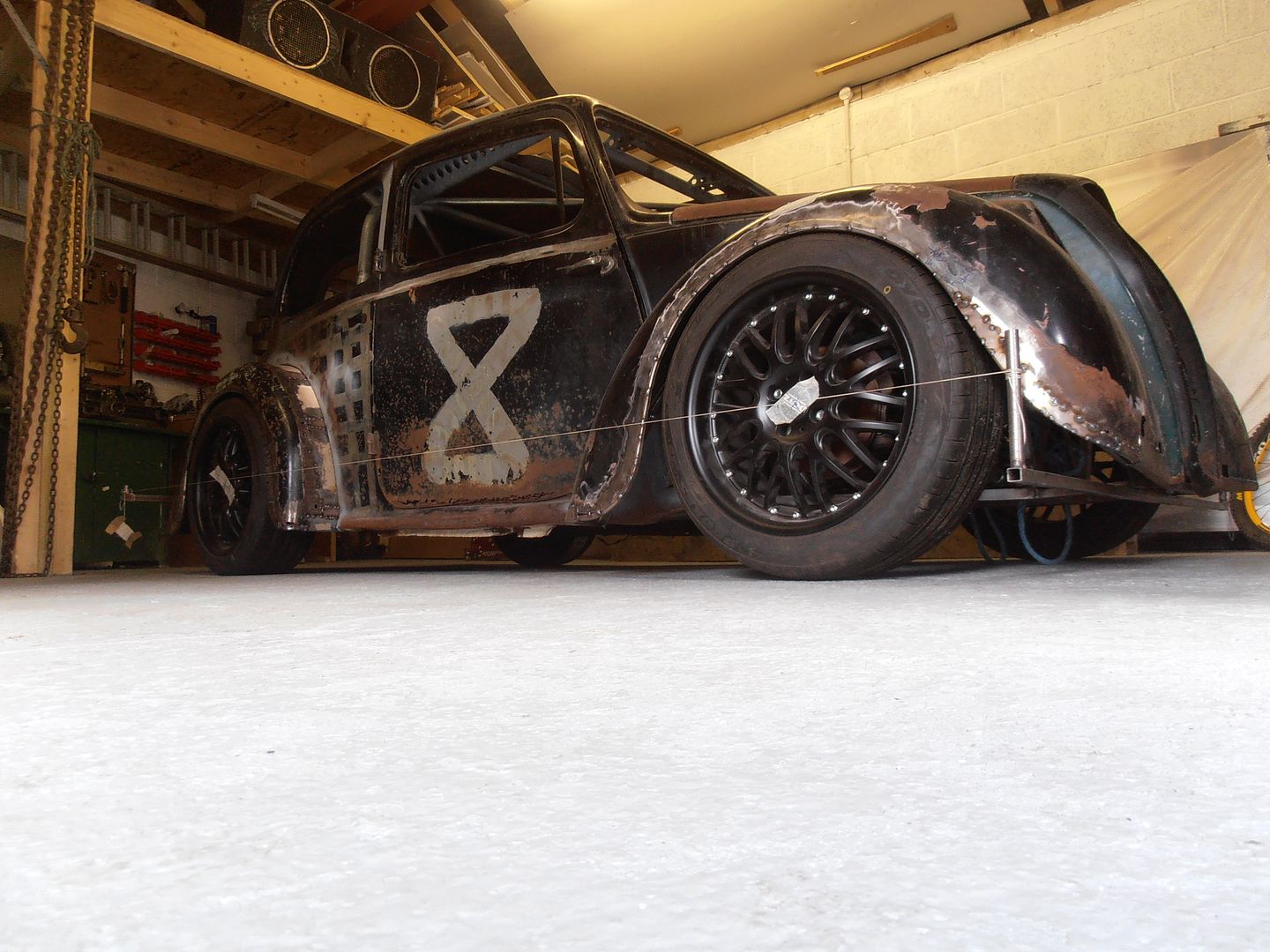
jonomisfit
Club Retro Rides Member
Posts: 1,787
Club RR Member Number: 49
|
|
Nov 27, 2021 20:52:09 GMT
|
Not an update really.... I sprayed some cavity wax into a few of the cavities, but had to buy more, so there is more to be done. No pictures as there isnt much to see..... except where i sprayed a few bits and need to clean it back off..... The car needs some lights, so bought this.  P1050786 P1050786 by jono_misfit, on Flickr  P1050787 P1050787 by jono_misfit, on Flickr  P1050788 P1050788 by jono_misfit, on Flickr bonnet view becomes interesting.  P1050790 P1050790 by jono_misfit, on Flickr The pod needs a re-paint and lamp fitting. I do quite like the green against the black though..... in a fetching shade of kawazaki green, which goes ok the the black. |
| |
|
|
|
|
jonomisfit
Club Retro Rides Member
Posts: 1,787
Club RR Member Number: 49
|
|
Jan 11, 2022 21:46:28 GMT
|
Hmmmm.  P1050969 P1050969 by jono_misfit, on Flickr Hmmmm.  P1050970 P1050970 by jono_misfit, on Flickr Mmmmh.  P1050971 P1050971 by jono_misfit, on Flickr Mmmmh.  P1050972 P1050972 by jono_misfit, on Flickr Ahhh.... Aluminium will make it all better.  P1050973 P1050973 by jono_misfit, on Flickr The next few things I need to do on the postman pat van are noisy, so chose not to be anti-social to my neighbours. I need to do something to mount the fuel filler to the side window and tie in the alumium barrier hose. Like so  P1050974 P1050974 by jono_misfit, on Flickr cut some ali  P1050975 P1050975 by jono_misfit, on Flickr turn it round...... ish  P1050976 P1050976 by jono_misfit, on Flickr cut a hole in the centre and mark some little holes  P1050977 P1050977 by jono_misfit, on Flickr drill  P1050978 P1050978 by jono_misfit, on Flickr at this point i curved it a little bit to match the profile of the window, then bolted the filler into it  P1050979 P1050979 by jono_misfit, on Flickr I'll drill a hole at the bottom and fit a barb for tank vent pipe to go to. Its a vented cap allegedly, but I cant see how it vents. so will do this. Then need a section for the foil barrier to clamp to. Rolly roll  P1050980 P1050980 by jono_misfit, on Flickr ends up like so  P1050981 P1050981 by jono_misfit, on Flickr I need to put a light bead on it to ensure the clamp has something to bite on. Better check it fits the foil ducting.  P1050982 P1050982 by jono_misfit, on Flickr Happy days. |
| |
|
|
jonomisfit
Club Retro Rides Member
Posts: 1,787
Club RR Member Number: 49
|
|
Jan 13, 2022 21:28:55 GMT
|
|
|
| |
|
|
jonomisfit
Club Retro Rides Member
Posts: 1,787
Club RR Member Number: 49
|
|
Jan 14, 2022 19:18:45 GMT
|
I used a sanding tube in the die grinder and cleaned up the hole.... which may have been a mistake as now there is loads of plastic dust in the car....  P1050990 P1050990 by jono_misfit, on Flickr drilled the mounting holes and test fitted  P1050991 P1050991 by jono_misfit, on Flickr  P1050992 P1050992 by jono_misfit, on Flickr welded up the join  P1050993 P1050993 by jono_misfit, on Flickr set up for welding the two parts together  P1050996 P1050996 by jono_misfit, on Flickr welded together.  P1050997 P1050997 by jono_misfit, on Flickr I'm not sure what was going on, but it was really difficult to get the welder welding consistently. I also put a few beads on the inside to ensure it doesnt crack on the joint. I also realised i needed it less deep as it was so deep you'd never get the jubilee clip on.... So i trimmed it back to the start of the bead.  P1050998 P1050998 by jono_misfit, on Flickr Test fitted all again  P1050999 P1050999 by jono_misfit, on Flickr  P1060001 P1060001 by jono_misfit, on Flickr  P1060002 P1060002 by jono_misfit, on Flickr If i get chance one night this week I may start the tube work to tie it to the tank. |
| |
|
|
jonomisfit
Club Retro Rides Member
Posts: 1,787
Club RR Member Number: 49
|
|
Jan 15, 2022 20:58:59 GMT
|
I finally found my tailgate gas struts and gave them a quick clean and a fit.  P1060036 P1060036 by jono_misfit, on Flickr I unfortunately managed to pop a corner of the tailgate perspex seal. So i'll need to pull it and re-bond it at some point. Doh I did a quick cut on the ali tube to start the filler link tube  P1060037 P1060037 by jono_misfit, on Flickr I cut it on the mitre saw. I wondered why it wasnt cutting to start with... that will be why  P1060039 P1060039 by jono_misfit, on Flickr Only a single carbide tooth left. I swapped in my spare blade and it cut through easily. |
| |
|
|
jonomisfit
Club Retro Rides Member
Posts: 1,787
Club RR Member Number: 49
|
|
Jan 21, 2022 21:46:10 GMT
|
I wasnt actually intending to make this today, so there are limited pics. I meant to cut the tube and then leave it to weld up one night. But I thought, i'll just check if I use tape if it lines up the right way. Which was a pain, so i thought i'd just tack it, then I trial fitted it and decided it needed a tweak, then re-tacked, then went f**k it and welded it all up. Fuel filler tube  P1060040 P1060040 by jono_misfit, on Flickr first time i've welded ali tubes with the tig, which came out OK.  P1060041 P1060041 by jono_misfit, on Flickr  P1060042 P1060042 by jono_misfit, on Flickr becuase I was doing a single cut at the tank end, to minimise the size of the space needed, it would have a pointed outer edge. This will just be a pain and end up popping the outter ducting i'm sure. So I cut the corner off and welded on a flat edge. It reduces the section slightly but i suspect it will have a negligable effect on the tank filling.  P1060043 P1060043 by jono_misfit, on Flickr starting to line it up in the car  P1060044 P1060044 by jono_misfit, on Flickr trim the tube, trim the hose  P1060045 P1060045 by jono_misfit, on Flickr and start aligning  P1060046 P1060046 by jono_misfit, on Flickr I fettled a bit more after this but neglected to take a pic. Next step is to remove it all and put a bead on the end of the tubes. |
| |
|
|
jonomisfit
Club Retro Rides Member
Posts: 1,787
Club RR Member Number: 49
|
|
|
|
I havent got round to making dies for the bead roller yet, so started a few other jobs. I cleaned back the edge of the fixing holes in the skirts (as i used them to get cavity wax into the sills) and put silver foil tape over them to prevent moisture ingress. Cleaned back, regreased, and fitted the door straps. Then onto the door cards. Cleaned them back and fitted some foam at key point to prevent rattling, and strong double sided tape in between the rivet holes.  P1060103 P1060103 by jono_misfit, on Flickr  P1060102 P1060102 by jono_misfit, on Flickr  P1060104 P1060104 by jono_misfit, on Flickr then fitted them  P1060105 P1060105 by jono_misfit, on Flickr not the greatest but they'll do for the moment. They're a thin skin of what looks like 200g carbon on the front face and a couple of layers of thin glass tissue on the back, set on a sheet of glass. then on to starting resolving this issue....  P1060107 P1060107 by jono_misfit, on Flickr the ballance bar tube lines up with the steering column..... so theres no space for the balance bar. Easy, just push the pedal forward to clear and adjust the push rods to the cylinders.......  P1060108 P1060108 by jono_misfit, on Flickr except..... thats where the pedal ends up  P1060109 P1060109 by jono_misfit, on Flickr A more comprehensive solution is needed A quick look on the internet says this is a common issue on these escort/sierra cosworth pedal boxes. Whilst i could have got the pedal box maybe 3mm further forward at the bulkhead when I set it. I need more.a lot more. 40mm more..... as its adapted from a standard pedal box I'll cut up an exsting pedal to start with, if Not i'll make a new pedal.  P1060110 P1060110 by jono_misfit, on Flickr start workign things out  P1060111 P1060111 by jono_misfit, on Flickr more working things out  P1060112 P1060112 by jono_misfit, on Flickr  P1060113 P1060113 by jono_misfit, on Flickr there's a large flared piece to clear the mount for the original cylinder push rod. I don't need it and its in the way. Mark for cutting.  P1060114 P1060114 by jono_misfit, on Flickr obstruction removed  P1060115 P1060115 by jono_misfit, on Flickr new tube position will be as so  P1060116 P1060116 by jono_misfit, on Flickr I did the noisy bits today so I can get chance to work on it during the week hopefully. |
| |
|
|
jonomisfit
Club Retro Rides Member
Posts: 1,787
Club RR Member Number: 49
|
|
|
|
|
|
| |
|
|
|
|
|
|
|
|
I like the updates i also like the door cards is that just flat carbon sheet cut to fit?
|
| |
|
|
jonomisfit
Club Retro Rides Member
Posts: 1,787
Club RR Member Number: 49
|
|
|
|
|
Yes, just flat carbon sheet that looks like wet lay up done on a sheet of glass.
|
| |
|
|
Darkspeed
Club Retro Rides Member
Posts: 4,874
Club RR Member Number: 39
|
|
|
|
|
Draw out the operating arcs - when you change positions like that you run the risk of losing linear motion.
Had this on the fury when the original builder modified the pedals - could not figure out why we could not bleed the brakes and the issue was the the full pedal throw was only half the M/C stroke due to the M/C pivot position in relation to pedal pivot .
You really want the mid point of the M/C stroke to be at the lowest part of the pedal operating arc - if you start past the mid point then you rapidly take the M/C pivot vertical rather than linear.
|
| |
|
|
jonomisfit
Club Retro Rides Member
Posts: 1,787
Club RR Member Number: 49
|
|
|
|
|
Thanks. Good advice.
Yes, I'm very much expecting a whole world of issues on this....
The main issue is overall the design doesn't work as the column is where the balance bar needs to be.
I suspect.... I may need to design a whole new pedal box with raised pivot heights to solve it all.
|
| |
|
|
jonomisfit
Club Retro Rides Member
Posts: 1,787
Club RR Member Number: 49
|
|
|
|
I took on board your suggestion Darkspeed and mocked up the arcs. Not 100% correct on some of the dims, but as close as I could measure with a single pair of hands. 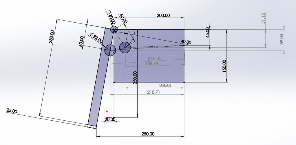 CAD mockup and results 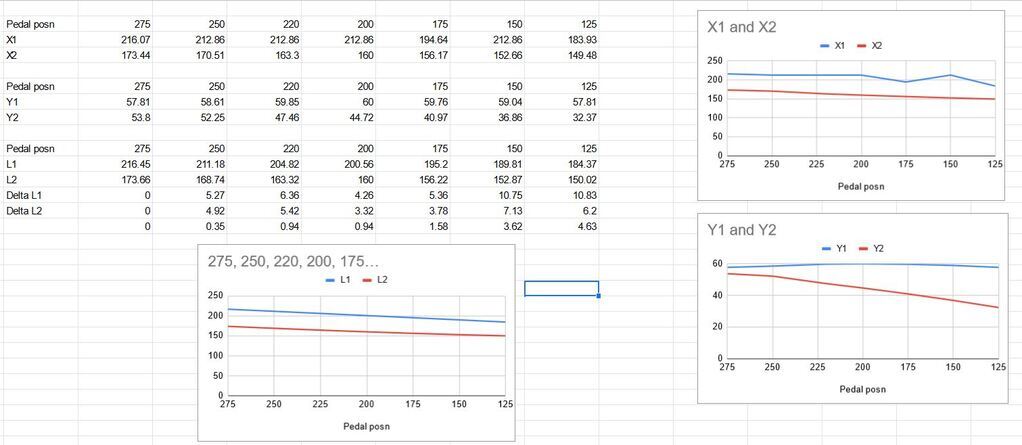 What does it say..... well..... Here in lies interpretation. X1/X2 are the horizontal distance from the balance bar centre to the master cylinder plane. Y1/Y2 are the vertical distance from the balance bar centre to a fixed vertical plane L1/L2 are the linear dimensions from the centre of the balance bar to the entry point to the master cylinder. You can see from the bottom graph that direct push is fairly linear in both cases. Correcting the offset shows there to be ~3.5mm delta over the first 100mm of travel and a further ~4.5mm delta over the next 100mm. I will be concerned if my brake pedal moves that far. In direct horizontal motion the original position is pretty linear for the first 75mm of travel before moving a bit as it goes over centre. The new position has a delta of 10mm over the same displacement of pedal. Y displacement is where the big difference expectedly is. The original posiiton has a swing of +/- 5mm over the full travel as its swinging centre arc. The new position move significantly. small to start with, but with a neight change of 20mm over full stroke. What does this mean? No idea, hopefully its not too big a movement and give a falling rate pedal etc. Anyone who knows better, your input is appreicated. |
| |
|
|
|
|
|
|
|
|
Will the push rods still clear the bores of the master cylinders on full travel?
|
| |
|
|
jonomisfit
Club Retro Rides Member
Posts: 1,787
Club RR Member Number: 49
|
|
|
|
|
I believe so. The angle of entry change over the full range isnt particulalry wide, and when I was looking at it earlier there is quite a range of articulation with the rod pushed in.
I was driving earlier and looking at the brake pedal when I was pushing it. I need to measure still, but would be suprised if the brake pedal was being depressed more than about 50mm. Even when braking very hard on purpose.
|
| |
|
|
jonomisfit
Club Retro Rides Member
Posts: 1,787
Club RR Member Number: 49
|
|
Feb 11, 2022 16:28:03 GMT
|
I have done a fair bit of digging about trying to find images of pedal boxes fitted in escort / sierra cosworths. After much looking I found this image on Jason Lepleys website of an sierra rally car (C) to them. 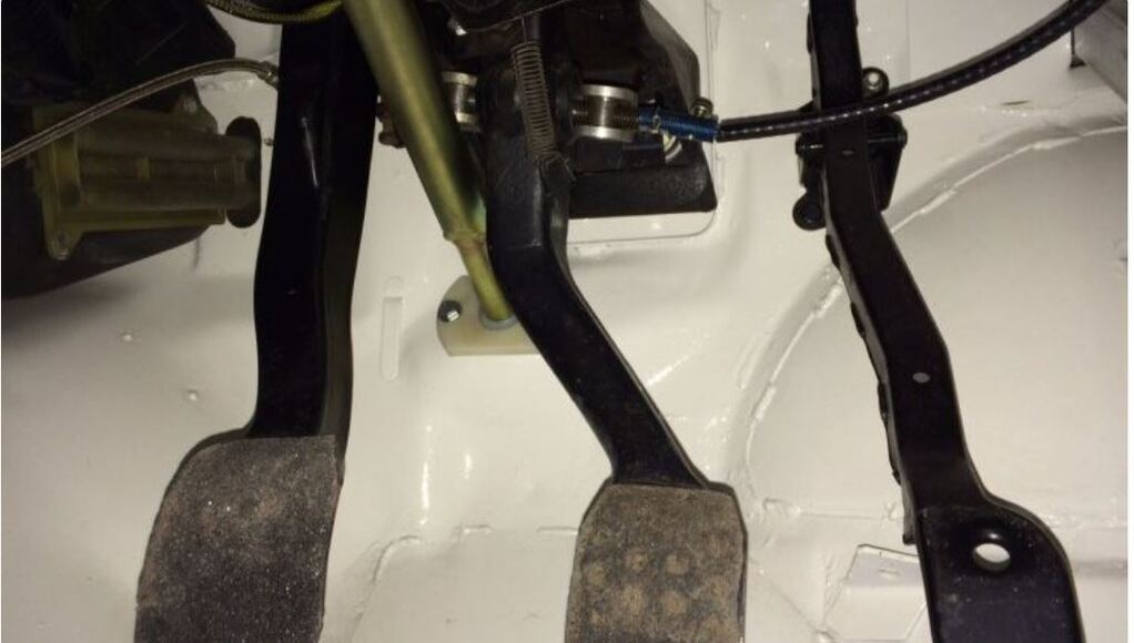 As you can see a similar issue to mine, of but what they've done is tilt the balance bar over so it just clears the column. I had a look at mine, and doing something simlar does mean it mainly clears. Pedal position is pulled forward by 10mm but would stop at the right point and just clear the column. You can see in the image the brake pedal is pulled forward slightly. Hmmm, i would like a bit more clearance than that though, and if i'm doign that I can sort the pedal ratio from the preset 4.65:1 to a better 5.6:1 wih a minor move of the pivot tube. A re-model in CAD gives. 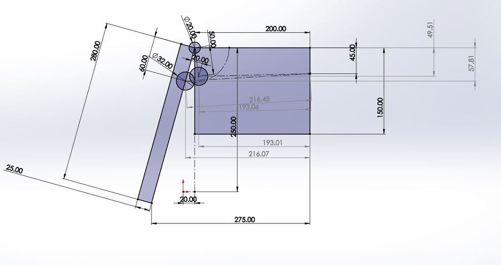 Reduce the centre pivot radius by 10mm and move forward by 20mm. Gives 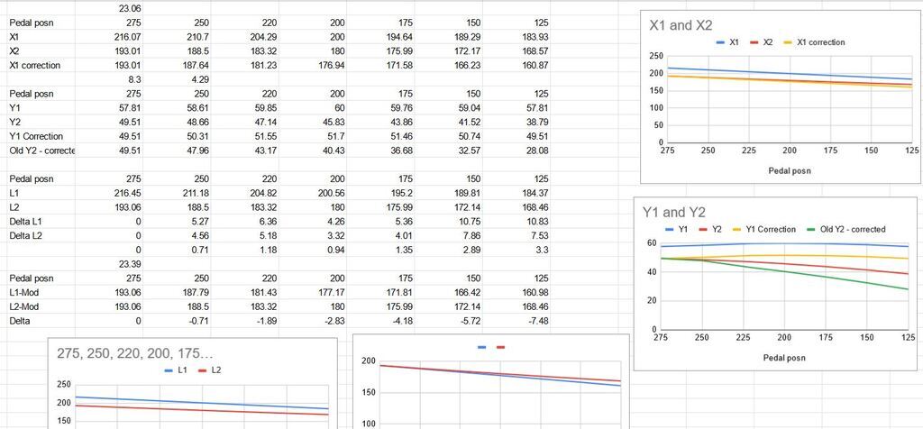 numbers are closer (red line v's yellow corrected for offset), less vertical gain (10mm v's 20mm) over the same arc v's the last itteration (green line) I think i'll try this and see what its like. Worst case I go back to plan B and make a new brake pedal. |
| |
Last Edit: Feb 11, 2022 16:31:03 GMT by jonomisfit
|
|
Darkspeed
Club Retro Rides Member
Posts: 4,874
Club RR Member Number: 39
|
|
Feb 11, 2022 21:26:55 GMT
|
Threw a few construction lines about together based on your drawing A Willwood 0.7 needs 32mm of stroke ( no idea what you are using- just arbitrarily chosen) - It looks like your pedal box geometry starts with the absolute ideal in respect of angular motion so your changes only result in an additional 7 degrees or so of arc motion for the same linear motion. If motion started later then that's when things go wrong quickly - If the full M/C stroke was 45mm it would not make it. So as you can see 15mm later than perfect geometry and the full M/C stroke starts to look doubtful. 15mm earlier is okay as its in linear acceleration rather than deceleration. - For want of a better description. The push rod length and the M/C stroke are fixed linear parameters that effect the required angular motion at the pedal. 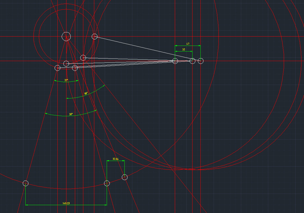 |
| |
|
|
jonomisfit
Club Retro Rides Member
Posts: 1,787
Club RR Member Number: 49
|
|
Feb 11, 2022 22:31:04 GMT
|
Thanks. Looking at your image I've tweaked my sketch a bit to be a bit more realistic (push rod remains constant, not point of intersect with the master cylinder) gives pre press 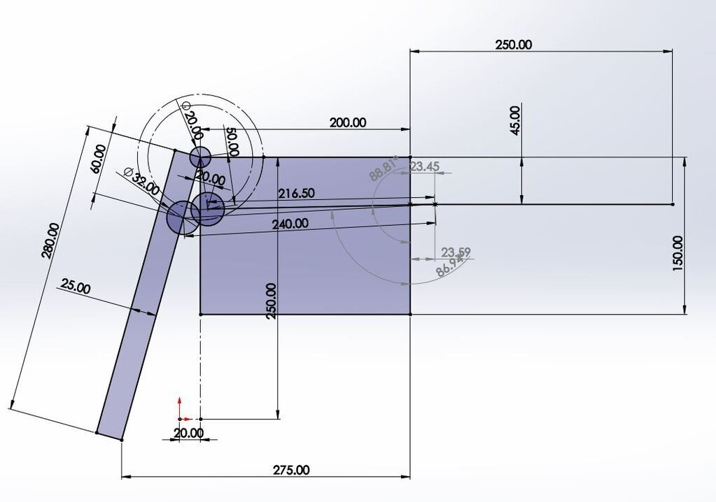 full pedal press (150mm) 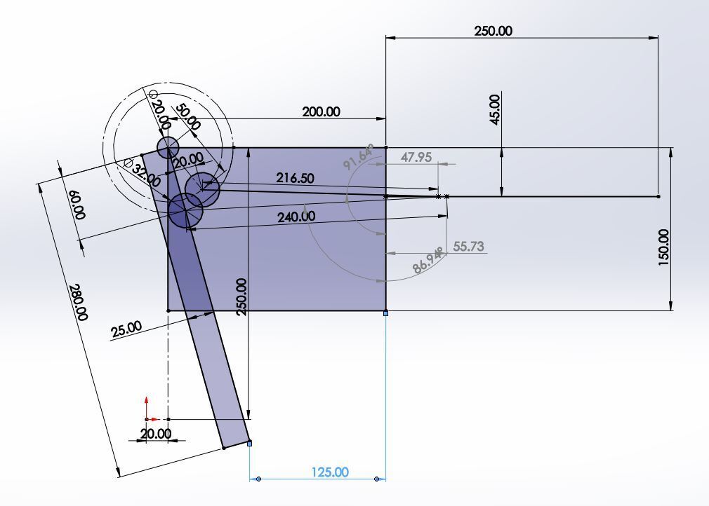 So this means i'm losing (in this model) 8mm of stroke by the change. 32.14mm of movement of the piston to 24.5mm of movement for the same pedal displacement. Part of that is due to the change in pedal ratio from 4.6:1 to 5.6:1 A quick check in CAD shows reseting the pedal ratio to previous gains back all but 1.25mm of the lost pushrod motion I think i'll need to just make it and see how it is in practice. |
| |
Last Edit: Feb 11, 2022 22:39:27 GMT by jonomisfit
|
|
Darkspeed
Club Retro Rides Member
Posts: 4,874
Club RR Member Number: 39
|
|
Feb 11, 2022 23:17:53 GMT
|
|
Just worth a check whilst you are doing the work at this point.
|
| |
|
|
jonomisfit
Club Retro Rides Member
Posts: 1,787
Club RR Member Number: 49
|
|
Feb 12, 2022 20:50:28 GMT
|
I sucked it up and made the pedal today. I bent very slightly along the dotted line  P1060144 P1060144 by jono_misfit, on Flickr tacked in  P1060145 P1060145 by jono_misfit, on Flickr second side position set square using a piece of 25mm box  P1060146 P1060146 by jono_misfit, on Flickr welded in  P1060147 P1060147 by jono_misfit, on Flickr other side tacked  P1060148 P1060148 by jono_misfit, on Flickr fully welded  P1060149 P1060149 by jono_misfit, on Flickr  P1060150 P1060150 by jono_misfit, on Flickr setup in the mill and bored out some 32mm holes  P1060151 P1060151 by jono_misfit, on Flickr balance tube fits snuggly  P1060152 P1060152 by jono_misfit, on Flickr welded in  P1060153 P1060153 by jono_misfit, on Flickr  P1060154 P1060154 by jono_misfit, on Flickr balance bar slides through nicely  P1060155 P1060155 by jono_misfit, on Flickr marked up for trimming  P1060156 P1060156 by jono_misfit, on Flickr trimmed  P1060157 P1060157 by jono_misfit, on Flickr If I get chance i'll look to strip the pedal box in the week and test fit the pedal and balance bar. |
| |
|
|
 P1050786 by jono_misfit, on Flickr
 P1050787 by jono_misfit, on Flickr
 P1050788 by jono_misfit, on Flickr
 P1050790 by jono_misfit, on Flickr
 P1050786 by jono_misfit, on Flickr
 P1050787 by jono_misfit, on Flickr
 P1050788 by jono_misfit, on Flickr
 P1050790 by jono_misfit, on Flickr


