 did you get any further with it?
 What follows was written in bits and pieces over time so I hope it all still makes sense and the pictures line up... Otherwise enjoy almost 2 years of updates!
The last update I posted was after RRG 18. Not a lot changed after that event, enjoyed putting some miles in finally (or as much as you can enjoy 7 mpg...).
 IMG_20190519_133924 by badgermk2, on Flickr
The next event in the calender was RRW 19. This was a fantastic event and the RX7 got out on track. She drove so well for a car on terrible tyres and suspension with rotten bushes. Happily held the top corner at 120mph feeling smooth the whole way. Only had 3 wobbly moments, first one was missing the braking point for a corner. I was off the proper line and unsettled the car but she made it round.
Next I forgot the chicane on the bottom straight at around 120mph, locked it up twice and the rear got a bit squirrelly but it snuck through.
Finally the rear stepped out on the last corner at 90mph, but the one thing I will always say about this car is despite the passive rear steer it slides very predictably, so thankfully it got round the corner just with some added style!
The only issue I had was constant overheating between each sprint, which may explain what happened next...
Unfortunately during the 4th sprint I noticed that the car was starting to lose boost. By the time I finished the 4th run I had nothing. Got it into the pit and it was clear the exhaust was blowing badly. I had the bay opposite the burger van and nobody sat by it could hear each other talk!
I left everything to cool down and did some afternoon passenger laps. Coming back it was clear that the wastegate had almost completely fallen off. This explained the lack of boost and noise, one of the bolts had done a runner so we got it bolted up best as we could. It was a bit quieter but still clearly not right. It was limped into the campsite, back to the track Sunday and then cruised home. On the way it had no boost but at about 6k it would pick back up a bit, this I thought confirmed the issues with the wastegate.
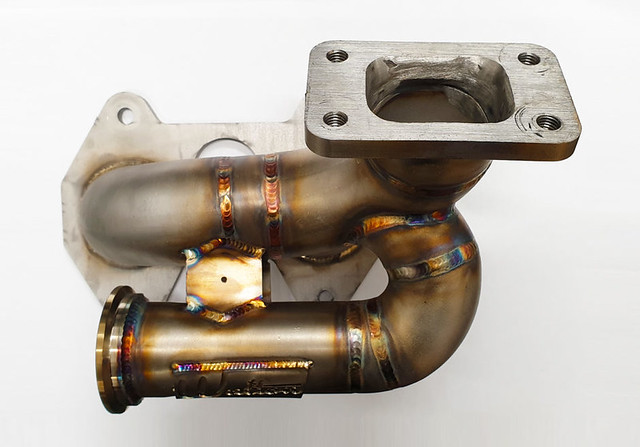
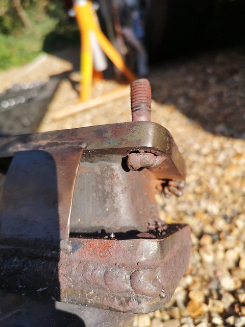
However once home I realised the turbo gasket was hanging out. Turns out it broke all the welds off the manifold studs and the turbo itself was barely attached anymore, the whole thing could be lifted up and moved around. Probably not the best idea to drive it home.
On inspection the welds on the manifold had no penetration, I'm surprised they hadn’t gone earlier. This is another in the list of things done poorly by the engine builder, consider the cost and time he had the workmanship is appalling.
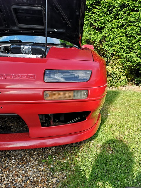
Anyway, onwards and upwards. I used this as an excuse to pull apart the front end and finally complete the V-mount I’ve had sat around for months at this point. The only issue was I only had a handful of weeks to get it running for a show.
 IMG_20190824_180150 by badgermk2, on Flickr
 IMG_20190919_154411 by badgermk2, on Flickr
-----------
Teardown:
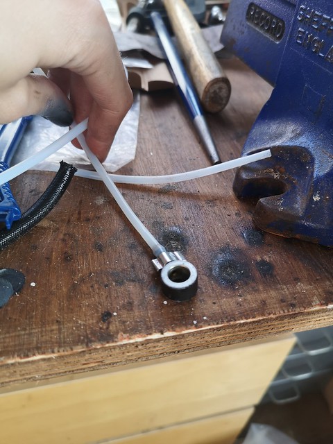
So work began on ‘repairing’ the turbo and installing the V-mount. I had hoped the turbo would be an easy fix, I replaced 3 broken studs with high tensile bolts and rewelded one that was just hanging on. Long story short this didn’t work! It held up for about 45 mins and then blew another gasket, but Ill get back to that.
 IMG_20190602_131613 by badgermk2, on Flickr
 IMG_20190930_154310 by badgermk2, on Flickr
Cardboard template:
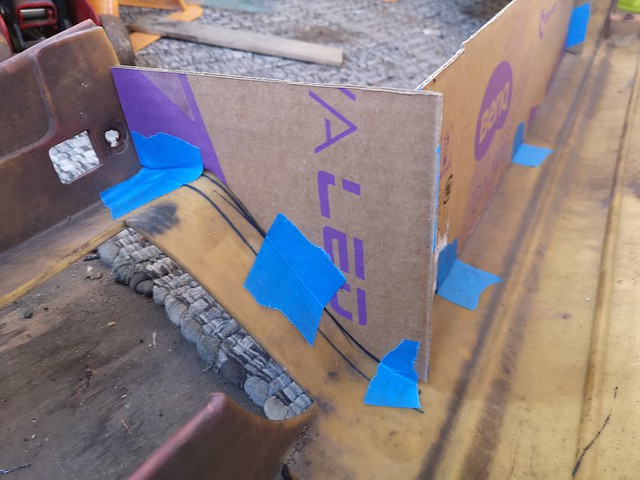
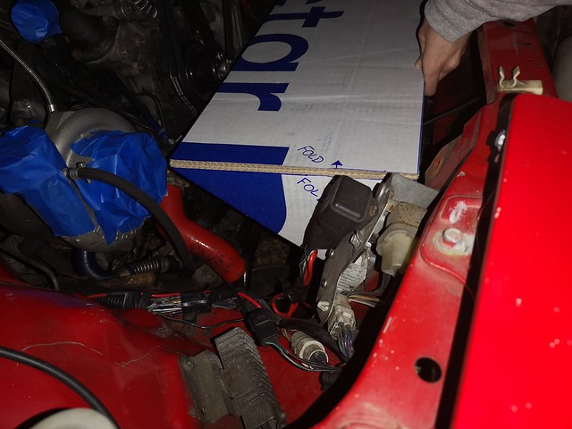
The V-mount I’m using is a Roose motorsport kit for an FD. So my first issue was does it fit? Followed swiftly by how does it fit? The FD slam panel is a lot further forward inline with the headlights whereas the FC is behind. I knew everything was going to be tighter so the first step was to get a template made up so I didn’t have to keep throwing the intercooler around.
 IMG_20190604_220453 by badgermk2, on Flickr
A very Blue Peter moment here with cardboard and sticky back plastic. But I got a very accurate replica which was a great help in working out how much needed to be cut and where it would mount.
 IMG_20190605_231457 by badgermk2, on Flickr
Measuring cuts:
The major work was cutting the slam panel. I wanted to make sure I was taking out the smallest amount of material possible. I measured this up as many times as possible until I was confident I was making the right choice. Started with the smallest possible cut and kept test fitting the template. Slowly removing material until the intercooler fit and was at the right angle.
 IMG_20190616_155546 by badgermk2, on Flickr
Making intake:
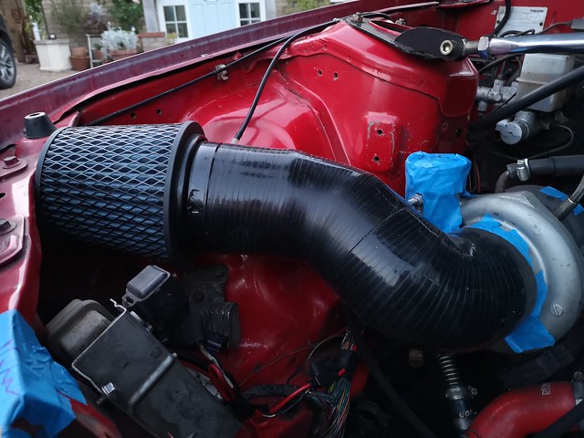
The first issue to become apparent was that the intercooler was starting to block the turbo intake so I bought some 4” silicon hose and joiners and made my own intake. This runs the tightest possible 90 degree so clear the intercooler then snakes over the arch and down behind the headlight. The intake also drove the intercooler angle as any more vertical or horizontal ended up interfering with the pipe. I’m hoping to eventually get this redone in aluminium which should be able to run a little smoother.
 IMG_20190615_213212 by badgermk2, on Flickr
 IMG_20190615_213218 by badgermk2, on Flickr
Test fit actual IC:
Once everything was cut and the intake was complete I could fit the actual intercooler and start working out the brackets. The intercooler comes with a tab to bolt to the FD slam panel so I wanted to use this. Its made to take 4 bolts which I am assuming are standard bolts for the FD but this didn’t line up with anything for the FC. Instead I marked out where these would bolt through and then made two straps.
 IMG_20190725_144013 by badgermk2, on Flickr
 IMG_20190630_190701 by badgermk2, on Flickr
Testing Radiator fit:
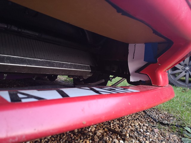
The next job was fitting the radiator, this was a lot easier now the intercooler was fitted. The kit has tabs on the back of the intercooler that mount the radiator so I already new where it was going to sit. It was only a question of what angle should it sit at and how far forward as that set the angel of the intercooler. I had to cut the old radiator mounting points so the new one could fit through. It was a lot simpler to measure but unfortunately was a lot harder to cut!
 IMG_20190630_190851 by badgermk2, on Flickr
Finding angle:
Once the radiator was fitted it was a case of holding the bottom with a jack to set the height and then moving it forward and back to get the angles right for both parts. Once I found the correct angle I needed to decide how to mount it.
The radiator came with two tabs, unfortunately one had to be completely removed or it wouldn’t’ve fit the other was cut down slightly but didn’t align with anything on the FC chassis.
However I did have two “brackets” welded to the car by a previous owner for the front mount intercooler. My plan was to make two arms that would bolt here and then hold the bottom of the radiator. These arms just have a bucket on the end that the radiator can sit in, there is no solid mounting.
Once the arms were in I went back to the tab on the radiator and welded in a bracket to the chassis that then bolts the radiator in. This bolt takes the main weight of the radiator and does most of the work to keep it in place. The two arms then don’t have to deal with a large force which would apply to the single bolts at the end, instead they push mainly horizontally against it. Although this setup is not perfect and could be reinforced for now it has had no issues holding the radiator and has stood up to the abuse. In future I may add two more bolts to the lower arms closer to the radiator which should alleviate any issues with weight.
 IMG_20190725_143926 by badgermk2, on Flickr
Testing IC piping:
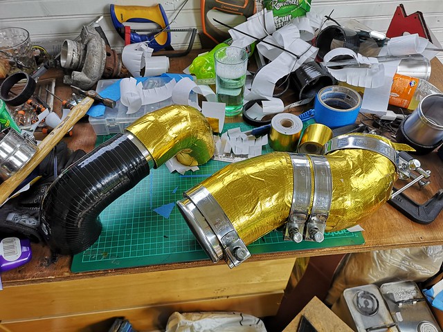
With everything now fitted in its final location I had to start on making the piping up. The kit came with coolant piping for the FD but unfortunately this wasn’t close to fitting the FC. Especially as the inlets were now on the other side of the car. With a series of pipes and joiners I managed to plumb in the intercooler and radiator.
 IMG_20190714_154850 by badgermk2, on Flickr
 IMG_20190717_170540 by badgermk2, on Flickr
Making oil cooler bracket:
The last thing to fit was the oil cooler. I will start by saying this is temporary and I have already started making up the new replacement cooler brackets. At this point I had about 3-4 days until the car was due at a show so I didn’t have time to change the oil lines. This meant trying to refit the cooler in a similar location to where it was.
The oil cooler placement was fairly simple for the reason that the oil lines forced it into one location, anywhere else either stretched or kinked the lines. Unfortunately it did mean it was stuck right behind the radiator hose and lost a lot of airflow, but as stated this was only a temporary fix.
 IMG_20190721_193339 by badgermk2, on Flickr
 IMG_20190721_193323 by badgermk2, on Flickr
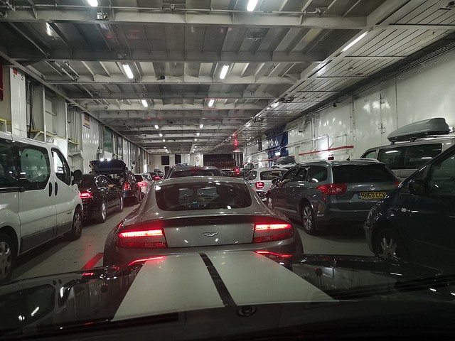
Happy that the push to finish the car was over it was time to pick up my rental and head to France!


